

Videofied OMV 611, OMV 210, OMV 712 Install Sheet
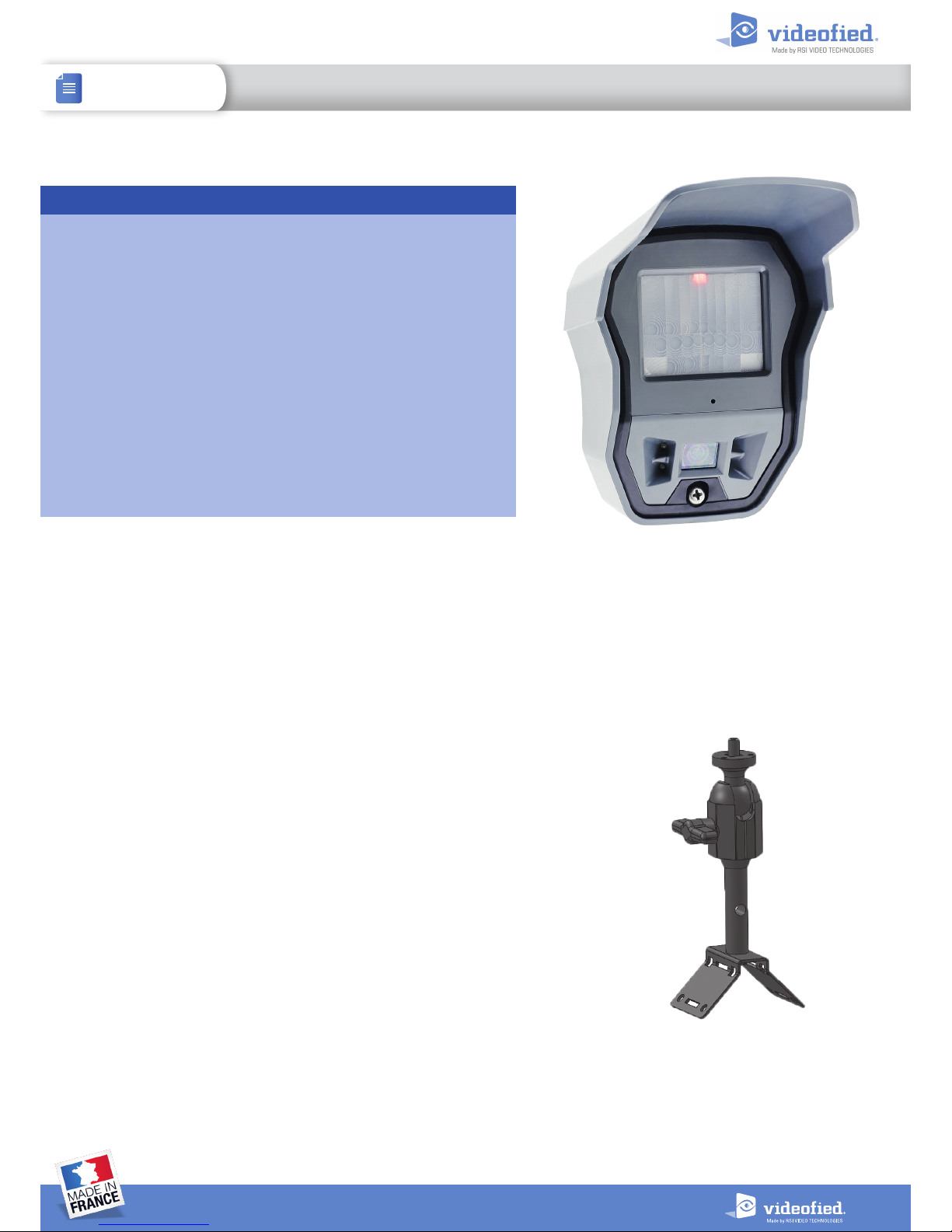
The OMV 210/611/712 MotionViewer is a wireless, battery
operated, motion activated or electrically activated outdoor
camera designed for use in Videofied®security systems.
• Powered by 4 Lithium batteries for extended battery life.
• 90° multi-purpose lens (by default).
• Provided op tional lenses: cu rtain, pet-imm une or long range b eam.
• 4 infrared LEDs for 12m night vision.
• Standard detection distance (up to 12 meters).
• Fully weatherproof (IP65) and temperature resistant
(-20°C/+60°C).
• Wall, cover and movement tamper triggered by tilt sensor.
• Transmits check-in/status signal every 8 minutes.
• 3 wired programmable inputs.
• 1 wired programmable output triggered on detection.
Product Summary
Installation Guidelines
For easier installation, programming and RF testing should be done to check
for good communication between the control panel and all system devices
before mounting system devices.
Install the detector and other system devices in the order of the following
steps:
> Programming/RF Testing - program detector and all other devices into the
control panel and test RF communication from each intended device location
to the control panel.
> Mounting - mount detector at the tested location.
Mounting
> Use proper tools and hardware.
> Mount camera between 2.5 m to 3 m height.
> The OMV MotionViewer detection distance may vary depending on
mounting (height, tilt). The OMV is not suitable to protect an area, it needs to
be used to protect an access point or any property.
> Mount detector aimed toward the spot to protect.
> In order to reduce false alarms, do not aim the detector toward vegetation,
a road, or unlimited space.
> Do not cover the Fresnel lens. Use only the provided masking kit to block
detection towards specific spots (trees, bushes, etc.).
MB11 0 Mounting kit for
Outdoor MotionViewer
DOC. - REF. 213-OMV
VERSION : AUGUST 2015
1
INSTALL SHEET
OMV OUTDOOR MOTION VIEWER
Programming/RF Testing/Mounting
The following provides summarized steps for device
programming, testing, and mounting. For complete details,
refer to the control panel installation manual.
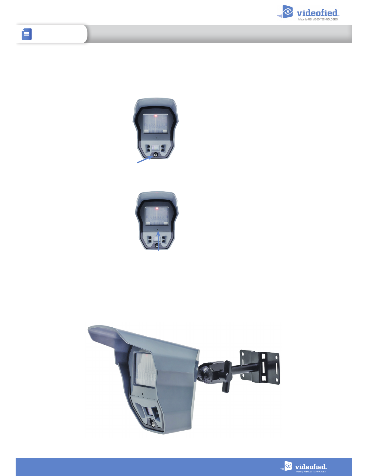
1 Separate the base from the box
2 Install 4 3.6V LS14500 SAFT
batteries observing correct polarity.
3 Put control panel into
Programming/Configuration mode.
4 Using a programmed
alphanumeric keypad, proceed
through menus until the display
shows ADD A NEW DEVICE.
5 Press OK/YES. the display shows PRESS PROGRAM
BUTTON OF DEVICE.
6 Press and release program button
on the OMV MotionViewer.
The OMV PIR flashes.
7 Wait for keypad display to show
CAMERA(1 - 25) PROGRAMMED. Press
OK/YES, the display shows RADIO
RANGE TEST? Press OK/YES again. The
camera LED starts flashing and keypad
display shows RF TEST.
8 Take the OMV camera to its intended mounting location
and make sure LED flashes continuously or you receive a 9/9
indicating good communication with the control panel.
9 Press OK/YES to end radio range test then press ESC/NO.
10 The keypad displays :
AREA ALLOCATION :
AREA : 1
Press either arrow button repeatedly until desired area number
appears then press OK/YES. By default all devices in Area 1 are
automatically delayed.
11 The display shows NAME + LOCATION:
Enter appropriate device name/location (up to 16 characters),
then press OK/YES. The display shows the device number and
name for your verification.
12 Mount the OMV on the MB110 or MBW110 Mounting kit.
Follow the installation guidelines shown in this document.
13 Press OK/YES. The display shows FUNCTIONAL DEVICE
TEST? Press OK/YES and verify camera operation. The
activation of the LED will determine the detection field.
14 Press OK/YES to end detection verification.
15 The display shows OPERATION COMPLETED or ADD A
NEW DEVICE? Press YES/OK. Repeat steps 1 – 14 for remaining
cameras.
16 When finished, exit from configuration mode.
Screw
Program but ton
2
INSTALL SHEET
OMV OUTDOOR MOTION VIEWER
3
INSTALL SHEET
OMV OUTDOOR MOTION VIEWER
Mounting Recommendations
For optimal use, OMV MotionViewer mounting shall respect the following recommendations.
Mounting height :
RSI Video Technologies recommends a 2,5m to 3m mounting height.
When you install the MotionViewer higher, the detection distance is raised. However the sensitivity is reduced
and the blind area under the MotionViewer is larger.
When you install the MotionViewer lower, the sensitivity is raised and the blind area under the detector is reduced.
However the detection distance will be reduced.
Tilt :
Raising or reducing the tilt, even slightly, has a big impact on the detection distance and on the blind area under the
MotionViewer. We recommend to slightly tilt the OMV to reduce its detection range and avoid false alarms.
To precisely determine the tilt angle use a smartphone app like Smart Protector (Android) or Pitch Gauge (iOs).
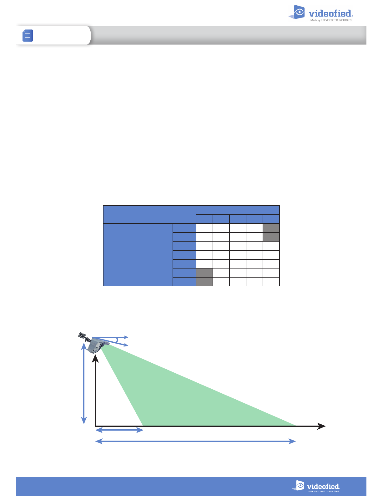
Blind Area
Max detection distance
Tilt
Mounting
height
Max detection distance :
MULTI-PURPOSE 90° LENS
Tilt angle
5° 10° 15° 20° 30°
Mounting height
2.5 m 12 m 9 m 7 m 6 m
2.75 m 13 m 9 m 7, 5 m 6 m
3 m 14 m 10 m 8 m 7 m 5 m
3.25 m 15 m 11 m 9 m 7 m 5 m
3.5 m 16 m 12 m 9 m 8 m 5,5 m
3.75 m 13 m 10 m 8 m 6 m
4 m 14 m 10 m 9 m 6 m
Theoretical values estimated for default sensitivity.
These values only represent the physical limits of the OMV detection and not its maximum detection range. Long range sensitivity is
reduced and depends on infrared detection properties (see page 5).
4
INSTALL SHEET
OMV OUTDOOR MOTION VIEWER
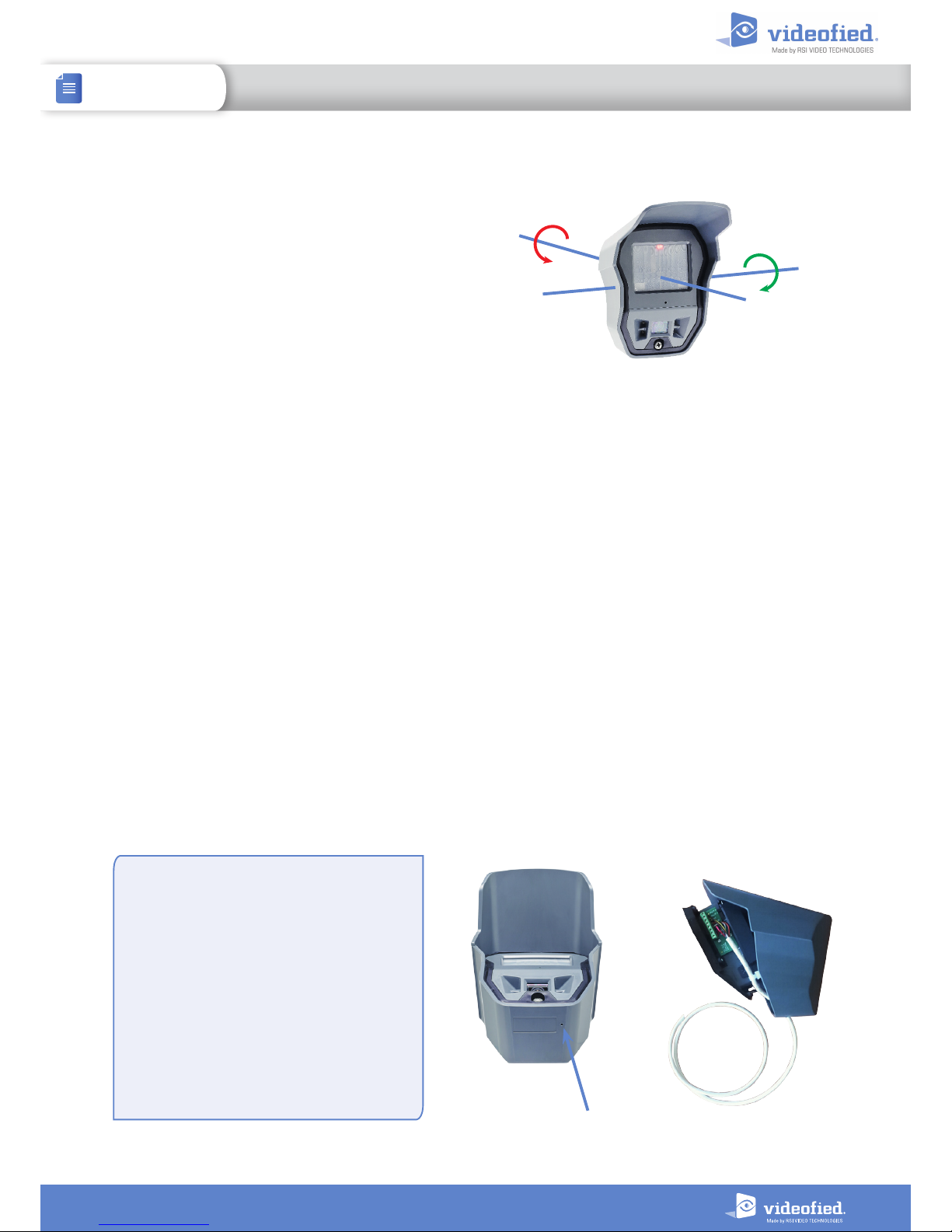
Tilt Tamper
The OMV MotionViewer can detect
manipulation thanks to its built-in electronic
accelerometer.
This device can detect shocks, movements,
wall or cover tamper but also changes in its
orientation.
When a movement of the OMV is detected, the
LED lights up for 3 seconds.
When it is armed, the OMV registers its position in space. If its orientation is significantly changed on its
transverse or longitudinal axis, a tamper alarm is sent to the panel. As for every Videofied device, the tamper
is active 24/7.
A new OMV position is defined automatically each time the MotionViewer is armed. If the OMV has been
moved, the “End of tamper” event is sent to the panel.
Longitudinal axis rotation
Transverse axis rotation
Wired inputs/output
The OMV MotionViewer has 3 built-in wired inputs. With these inputs, other detection systems can be
associated with the OMV.
IN1 and IN2 inputs : Normally open wired inputs. These inputs are enabled when the OMV is
armed. When triggered, an INTRUSION event is sent to the panel and the
OMV captures a video.
IN3 input : Normally open wired input. This input is enabled 24/7. When triggered,
a TAMPER event is sent to the panel.
The OMV also has one built-in wired output. This output can activate a wired system when the OMV infrared
detection is triggered.
OUT output : 24 V/ 10 0 m A open drain contact. When the OMV is triggered, the output
contact closes for 3 seconds and opens.
Inputs/outputs wiring
Two drilling punch marks are visible on the
OMV case. One under the case and one inside
the box on the bottom right.
Drill a hole in one of these punch marks to
pass the wire through and connect the inputs/
outputs terminal.
IMPORTANT :
Once the wire is connected, protect the
inside of the case with a silicone watertight
seal.
Punch mark
 Loading...