

Videofied ISMV 200, ISMV 702, ISMV 601 Install Sheet
The ISMV 200/601/702 is a wireless, batter y-powered, motion
activated indoor video c amera. It can also be activated by user request.
• Wireles s technology for optimal se curity.
• Color video (lighted sites) or black & white (night vision).
• Infrared LED for night vision.
• Standard motion coverage lens.
• Wall and cover tamper.
• Powered by 3 Lithium CR123A batteries for extended autonomy.
• Device supervision every 8 minutes.
• Video capture and transmission in «streaming mode» on user request.
Main features
Installation guidelines
For an easier installation, programming and RF testing should be done to check
for good communication between the control panel and all system devices
before mounting.
Install the detector and other system devices in the following order:
>
Programming / RF Testing: Program detector and all other devices into the
control panel and test RF communication at each intended device location to the
control panel.
>
Mounting: Mount detector at the tested location.
Mounting rules
> Use proper tools and hardware.
> Mount indoors in a temperature controlled environment.
> Mount camera 2.1m from the floor.
> Respect Top and Bottom side of the Motion Viewer
> When possible, mount in a wall corner in order to aim at a
complete room
> Mount detector on an outside wall, aimed at area to protect.
> Do not aim detector at windows, especially those that let in direct sunlight, or at
heat sources such as lamps, fireplaces, radiators and heating vents.
> Do not aim detector at moving objects such as curtains, fans or animals.
> Do not cover the Fresnel lens.
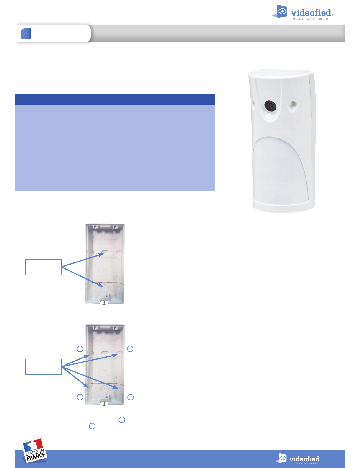
Corner
mounting holes
Flat wall
mounting holes
Only use 2 of the 4
mounting holes.
or .
1
1 2
2
1
2
ISMV STREAMING MOTIONVIEWER
INSTALL SHEET
DOC. - REF. 212-ISMV
MODIF. DATE :NOVEMBER 2016
1
2
INSTALL SHEET
ISMV STREAMING MOTIONVIEWER
Programming / RF Testing / Mounting
The following provides summarized steps for device
programming,testing, and mounting. For complete details,
refer to the control panel installation manual.
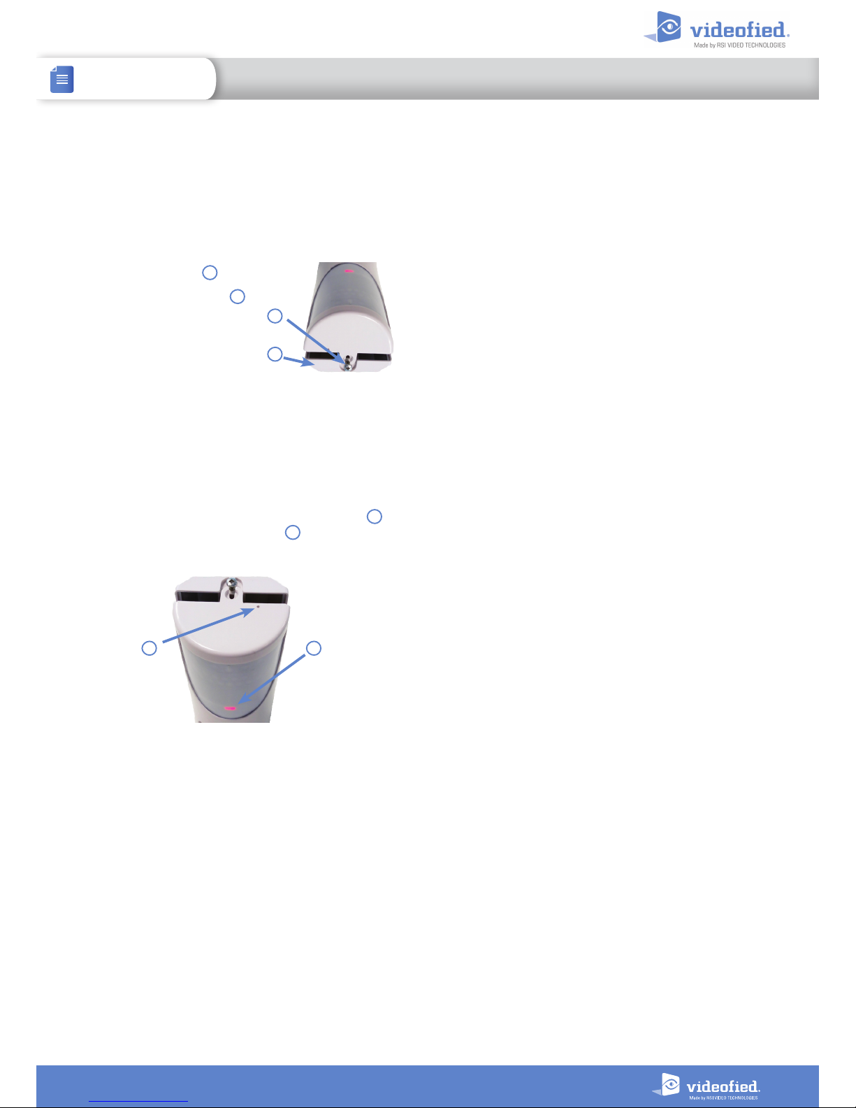
1 Loosen bottom screw
Separate base from ISMV
2 Install 3 CR123A 3V batteries, observing correct polarity.
3 Enter the panel into programming/configuration mode.
4 Using a programmed alphanumeric keypad, procee d through
menus until the display shows ADD A NEW DEVICE.
5 Press OK. The display shows PRESS PROGRAM BUTTON OF
DEVICE.
6 Press and release the program button on the ISMV using
a paper clip. The ISMV LED flashes red .
7 Press OK, the keypad displays RADIO RANGE TEST ? Press
OK again. The ISMV LED starts flashing and the keypad displays
TEST IN PROGRESS.
8 Move the ISMV to the intended mounting location and
confirm the signal is 9/9, indicating good communication with
the control panel.
9 Press OK to end the radio range test then press ESC/NO.
10 The display shows :
AREA ALLOCATION :
AREA : 1
Press either arrow button on the keypad until the desired AREA
number appears, then press OK. By default all devices in area 1
will be subject to the entry and exit delays.
11 The screen displays NAME + LOCATION :
Enter an appropriate device name (up to 16 characters). The
name of the device should describe its intended mounting
location or zone. Press OK. The display will show the device
number and name for your verification.
12 Mount the ISMV on the wall:
> Follow the mounting rules on page 1.
> Hold the ISMV base against the mounting surface and mark
the appropriate mounting holes.
> Drill pilot holes and install anchors where needed.
> Place the base on mounting surface so that the pilot holes line
up and secure base with appropriate screws.
> Attach camera to base and secure with screw if required.
13 Press OK. The display shows FUNCTIONAL DEVICE TEST?
Press YES again and verif y IMV operation. The red LED indicates
the detection field.
14 Press OK to end the detection test.
15 The display shows ADD A NEW DEVICE? Repeat steps 1-14
for remaining devices.
16 When finished, exit from configuration mode by pressing
and holding the ESC/NO for 5 seconds.
Wait for the keypad to display : CAMERA REGISTERED.
2
1
3
3
4
4
1
2
 Loading...