

Videofied IMV200 Product Installation Sheet
Indoor MotionViewer IMV200
PRODUCT INSTALLATION SHEET
Made by RSI VIDEO TECHNOLOGIES 2225-IMVIS January - 2013
Product Summary
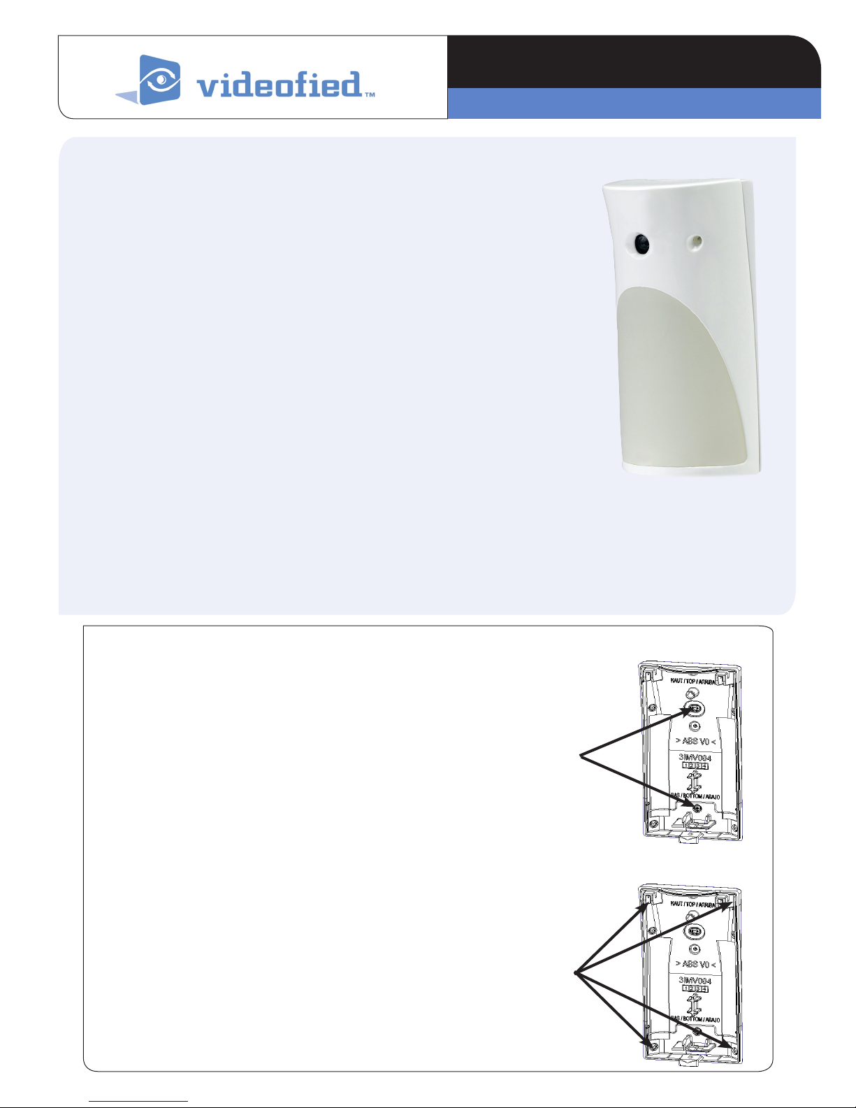
The MotionViewer IMV200 is a wireless, indoor motion activated camera
designed for use in a Videofied™ security system. The camera includes the following features:
Lithium batteries for long life
>
Color Day / B&W night
>
Wide angle lens
>
Infrared LEDs for night illumination
>
Standard motion coverage lens (30 ft./9 m distance)
>
Dual tamper function provides detection of both wall and cover tamper.
>
Transmits check-in/status signal every 8 minutes
>
Installation Guidelines
For an easier installation, programming and RF testing should be done to check for good
communication between the control panel and all system devices before mounting.
Install the detector and other system devices in the following order:
Programming / RF Testing: Program detector and all other devices into the
>
control panel and test RF communication at each intended device location to
the control panel.
Mounting: Mount detector at the tested location.
>
Mounting Rules
> Use proper tools and hardware.
> Mount indoors in a temperature controlled environment.
> Mount camera 2.0 to 2.3 m (6.6 to 7.5 ft.) from the floor.
> Respect Top and Bottom side of the Motion Viewer
Flat Wall
Mounting
Holes
> When possible, mount in a wall corner in order to aim at a complete
room
> Mount detector on an outside wall, aimed at area to protect.
> Do not aim detector at windows, especially those that let in direct
sunlight, or at heat sources such as lamps, fireplaces, radiators, and
heating vents.
Flat Wall Mounting
Corner Mounting
> Do not aim detector at moving objects such as curtains, fans or
animals.
> Do not cover the Fresnel lens
Corner
Mounting
Holes
www.videofied.com
①
②
①
Indoor MotionViewer IMV200
Programming/RF Testing/Mounting
The following provides summarized steps for device
programming, testing, and mounting. For complete details, refer
to the control panel installation manual.
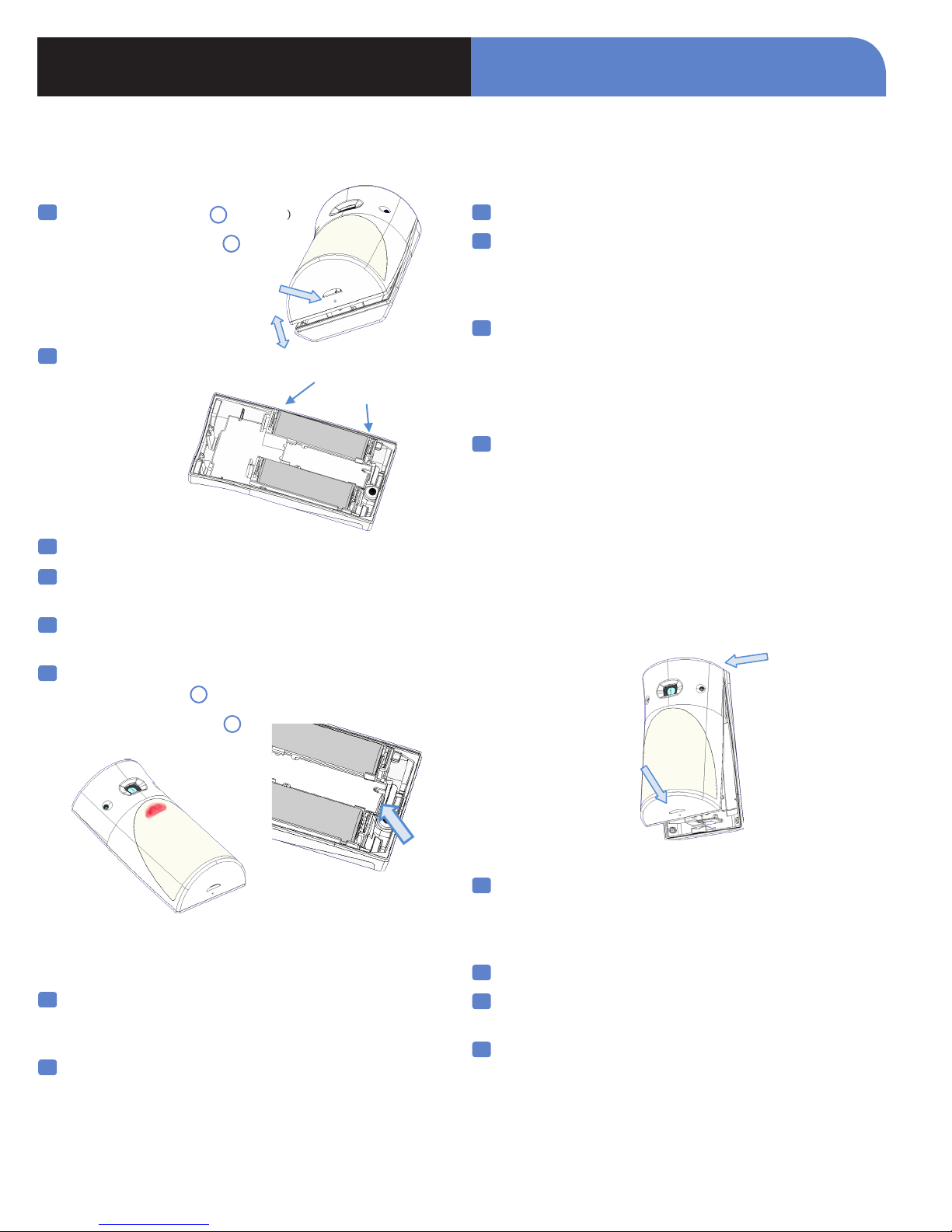
1
Loosen bottom screw. 1 (if present)
INSTALLATION DATA SHEET
9
Press YES to end the Radio Range Test, then press ESC/NO.
Separate base from IMV. 2
②
2
Install 2 SAFT LS14500 3.6v batteries, observing correct
polarity.
+
*Check that the LED
flashes before staying
RED
3
Put control panel into programming/configuration mode.
4
Using a programmed alphanumeric keypad, proceed through
menus until the display shows ADD A NEW DEVICE.
5
Press Yes . The display shows PRESS PROGRAM BUTTON OF
DEVICE.
6
Press and release program button on the IMV using your
finger or a screw driver 1 .
10
The display shows AREA ALLOCATION; AREA: 1. Press
either arrow button on the keypad until the desired AREA
number appears, then press YES. By default all devices in
area 1 will be subject to the entry and exit delays.
11
The display shows NAME + LOCATION:
Enter an appropriate device name (up to 16 characters). The
name of the device should describe its intended mounting
location or zone. Press YES. The display will show the
device number and name for your verification.
12
Mount the IMV on the wall:
- Follow the mounting rules on page 1
- Hold the IMV base against the mounting surface and mark
the appropriate mounting holes.
- Drill pilot holes and install anchors where needed.
- Place base on mounting surface so that the pilot holes line
up and secure base with appropriate screws.
- Attach camera to base and secure with screw if required.
①
The IMV LED flashes red 2 .
Wait for keypad display to show MOTIONVIEWER (1 - 24)
PROGRAMMED.
7
Press Yes. The display shows RADIO RANGE TEST? Press
Yes again. The IMV LED starts flashing and keypad display
shows TEST IN PROGRESS.
8
Move the IMV to the intended mounting location and make
sure you receive a 5/5 or 9/9 indicating good
communication with the control panel.
②
13
Press YES. The display shows FUNCTIONAL DEVICE TEST?
Press YES again and verify IMV operation. For example,
wave your hand in front of the sensor to activate the LED
which indicates detection.
14
Press YES to end the detection verification
15
The display shows ADD A NEW DEVICE? Repeat steps 1-14 for
remaining MotionViewers.
16
When finished, exit from configuration mode by pressing and
holding the ESC/NO for 5 seconds.
www.videofied.com
 Loading...