

Videofied DCV651 Product Installation Sheet
Outdoor MotionViewer DCV651
PRODUCT INSTALLATION SHEET
Made by RSI VIDEO TECHNOLOGIES 2204 - OMVIS March 2012
Product Summary
The Outdoor MotionViewer Model DCV651 is a wireless,
battery operated, outdoor motion activated camera designed for use in RSI Video Technologies security systems.
Motion-activated cameras are intended for applications
where video verification of intrusion alarms is necessary or
desired.
Lithium batteries for long life
>
Wide angle lens
>
Infrared LED for night illumination
>
Standard motion coverage lens (30 ft./9 m distance)
>
IP65 weather proof housing
>
> Low Temperature operation (-20°f to + 140°f)
Transmits check-in/status signal every 8 minutes
>
Programming/RF Testing
The following provides summarized steps for device
programming and testing. For complete details, refer
to the control panel installation manual.
1
Remove all 4 screws, separate base
from camera and install batteries.
2
Put control panel into
programming/configuration mode.
3
Using a programmed alphanumeric
keypad, proceed through menus
until the display shows ADD A
NEW DEVICE.
4
Press Yes . The display shows PRESS
PROGRAM BUTTON OF DEVICE.
5
Press and release program button
on the MotionViewer.
The camera LED flashes. Wait for
keypad display to show CAMERA
(1 - 25) PROGRAMMED.
6
Press Yes . The display shows
RADIO RANGE TEST? Press Yes
again. The camera LED starts
flashing and keypad display
shows RF TEST ( #/5 or #/9).
Installation Guidelines
For easier installation, programming and RF testing
should be done to check for good communication between
the control panel and all system devices before mounting
system devices.
Install the detector and other system devices in the order
of the following steps:
Programming/RF Testing - program detector and
>
all other devices into the control panel and test RF
communication from each intended device location
to the control panel.
Mounting - mount detector at the tested location.
>
7
Take camera to its intended mounting location and
make sure LED flashes continuously or you receive a 5/5
or 9/9 indicating good communication with the control
panel.
9
Press YES to end radio range test, then press Esc/No.
10
The display shows AREA ALLOCATION AREA: 1. Press
either arrow button repeatedly until desired AREA
number appears, then press Yes.
11
The display shows NAME + LOCATION. Enter appropriate
device name/location (up to 16 characters), then press
Yes. The display shows the device number and name
for your verification.
12
The display shows FUNCTIONAL DEVICE
TEST? Press Yes again and verify camera operation.
For example, wave your hand in front of the sensor to
activate its LED indicating detection. (walk test LED)
13
Press Yes to end detection verification.
14
The display shows OPERATION COMPLETED or ADD A
NEW DEVICE? Press Ye s
Repeat steps 1 – 14 for remaining cameras.
15
When finished, exit from configuration mode.
www.videofied.com
Outdoor MotionViewer DCV651
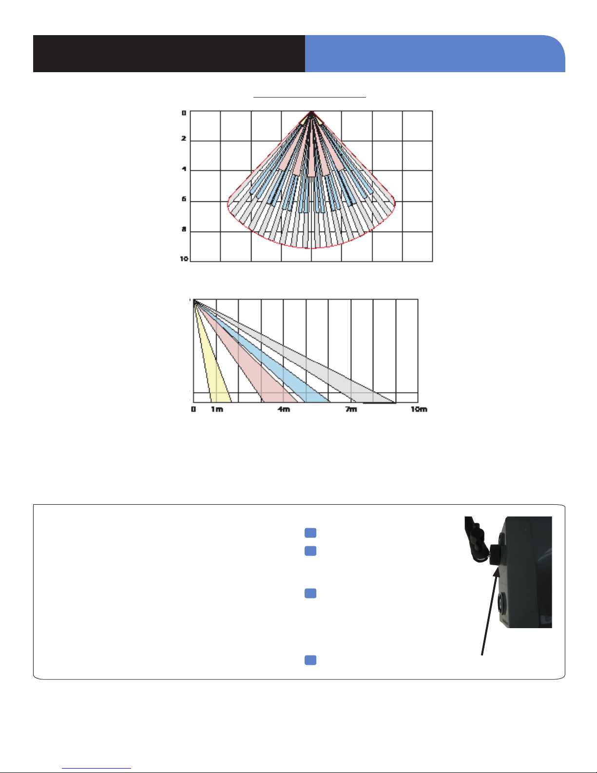
PIR Detection Pattern
INSTALLATION DATA SHEET
WARNING : Do not cover the Fresnel lens !
Mounting
Use proper tools and hardware.
>
Mount using 1/4” x 20 thread mounting bracket only.
>
Mount camera 7.5 to 9 feet (2.3 to 2.8m) from the floor.
>
Mount detector aimed at area to protect.
>
Do not aim detector at windows, especially those that
>
let in direct sunlight, or at heat sources such as lamps,
fireplaces, radiators, and heating vents.
Do not aim detector at moving objects such as curtains,
>
fans or animals.
1
Separate base from camera.
2
Hold mount base against
mounting surface and mark the
appropriate mounting holes.
3
Place camera mount on
mounting surface
so holes line up with
pilot holes/anchors and secure
base with appropriate screws.
4
Thread the MotionViewer onto the mount
www.videofied.com
 Loading...