

Videofied CT 600, CT 610 Installation Instructions Manual
Door Contact Models CT600/610
INSTALLATION INSTRUCTIONS
Manufactured by RSIalarm Document No. 1008-c November 2006
Product Summary
The Door Contact Models CT 600 (white) CT 610 (brown),
are wireless, universal door contacts designed for use in
RSIalarm™ security systems. The contact includes the
following features:
Lithium battery for long life
>
External input for normally closed (NC) intrusion devices
>
Dual tamper function provides detection for both wall
>
and cover tamper.
Transmits check-in/status signal every 8 minutes
>
Programming/RF Testing
The following provides summarized steps for device
programming and testing. For complete details, refer
to the control panel installation manual.
1
Loosen bottom screw, separate base
from detector and install battery.
2
Re-attach base to secure tamper switch.
3
Put control panel into programming/
confi guration mode.
4
Using a programmed alphanumeric
keypad, proceed through menus
until the display shows ADD A
NEW DEVICE.
5
Press Yes . The display shows
PRESS PROGRAM BUTTON OF DEVICE.
6
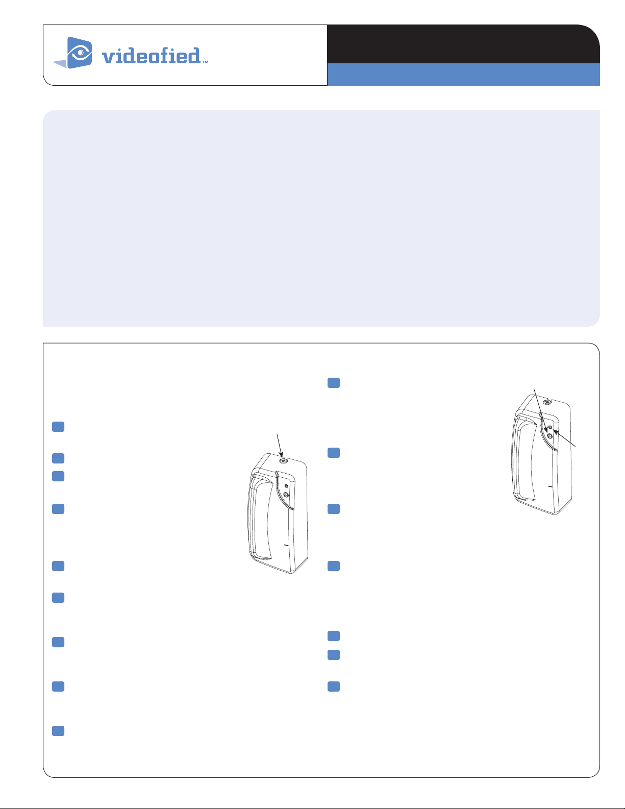
Press and release program button on detector using a
paper clip end. The detector LED fl ashes. Wait for keypad
display to show DETECTOR (1 - 25) RECORDED.
7
Press Yes . The display shows RADIO RANGE TEST?
Press Yes again. The detector LED starts fl ashing and
keypad display shows TEST IN PROGRESS.
8
Take detector to its intended mounting location and
make sure LED fl ashes continuously, indicating good
communication with control panel.
Screw
Installation Guidelines
For easier installation, programming and RF testing
should be done to check for good communication between
the control panel and all system devices before mounting
system devices. Install the detector and other system
devices in the following order:
Programming/RF Testing—program detector and
>
all other devices into the control panel and test RF
communication from each intended device location
to the control panel.
Mounting—mount detector at the tested location.
>
10
The display shows AREA
ASSIGNMENT AREA: 1. Press
either arrow button repeatedly
until desired AREA number
appears, then press Yes.
11
The display shows PROTECT AN
EXTERNAL ACCESS? Press Yes or
Esc/No, whichever is appropriate
for this device.
12
The display shows NAME + LOCATION.
Enter appropriate device name/location (up to
16 characters), then press Yes. The display shows
the device number and name for your verifi cation.
13
Press Yes . The display shows FUNCTIONAL DEVICE
TEST? Press Yes again and verify detector operation.
For example, move magnet next to detector to make
LED go out, then move magnet away from detector
to make LED turn on indicating detection.
14
Press Yes to end detection verifi cation.
15
The display shows ENTERING A NEW DEVICE?
Repeat steps 1 - 14 for remaining detectors.
16
When fi nished, exit from confi guration mode.
Program Button
LED
9
Press Yes to end radio range test, then press Esc/No.
www.videofied.com
Mounting
Use proper tools and hardware.
>
Mount indoors in a temperature-controlled environment.
>
Mount detector on frame and magnet assembly on movable
>
opening (door, window).
When using internal switch, mount so that detector and
>
magnet alignment marks are lined up with each other.
When using internal switch, do not exceed 3/8-inch/10 mm
>
gap between detector and magnet.
Magnet spacers must be used to match magnet height with
>
detector to ensure correct alignment and functionality.
Note: If detector installation only requires use of the external input,
magnet assembly installation is not required.
1
Separate base from detector.
2
Hold detector base against
mounting surface and mark
the two mounting holes.
3
Drill pilot holes into mounting
surface.
4
Mount detector base to surface
using appropriate screws.
5
If using external input, run
2-conductor, 22-gauge wire from
protection point to detector.
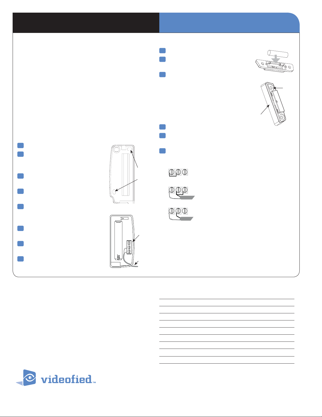
6
Connect hardwire circuit wires to
external input screw terminals.
7
Connect other end of wires to
initiating device.
8
Attach detector to base, making
sure every wire is secure with screws.
Mounting
Holes
External
Input
Terminals
To
Initiating
Device
INSTALLATION INSTRUCTIONSDoor Contact Models CT600/610
9
Insert magnet into magnet holder.
10
Attach wedges to magnet holder
as needed to match height of detector.
11
Hold magnet base against
mounting surface and mark
the two mounting holes.
Note: Be sure alignment marks on detector
and magnet base are lined up with each other
and that there is no more than a 3/8-inch
(10 mm) gap between them.
12
Drill pilot holes into mounting surface.
13
Insert screws through magnet base and wedges,
Wedge
Base
then secure to mounting surface.
14
Attach cover to magnet holder.
Internal Reed Switch
External Reed Switch
The internal jumper shown
in position for possible connections.
Int + Ext Reed Switch
1. Internal reed switch only
2. External reed switch only
3. Both Int. and Ext. switch use
External Input Terminal, Jumper position and wiring
Note: The internal jumper wire is only used for internal or external
switch use. The jumper is not used when both Int. and Ext switches are
used together. The default jumper position is in the Internal switch mode.
it only has to be changed if wiring external switches to the transmitter.
Regulatory Information
FCC Part 15
This device complies with FCC Rules Part 15.
Operation is subject to the following two conditions:
1.) This device may not cause harmful interference and,
2.) this device must accept any interference that may be
received, including interference that may cause undesired
operation.
Changes or modifi cations not expressly approved by RSIalarm,
Inc. can void the user’s authority to operate the equipment.
4455 White Bear Parkway, Suite 700
White Bear Lake, MN
USA
© 2007 RSIal arm™ Videofi ed® is a Re gistered Trademark of RSIal arm™.
2
S
View is a regis tered trademark o f RSIalarm™. Specifi catio ns subject to change wi thout notice.
Specifications
Panel Compatibility V-6000
Operating Frequency 915 MHz. 25 frequencies
Radio type Spread Spectrum Bidirectional RF
Power Requirements One 3.6 V lithium battery
Battery Type LS14500
Operating Temperature 32° - 104° F (0° - +40° C)
Maximum Relative Humidity 70% non-condensing
Dimensions (LxWxD) 3 in. x 1-3/8 in. x 1 in. / (80 mm x 35 mm x 23 mm)
Weight 1.4 oz. (40 g) without battery
UL Listings 1023 (applied for)
Toll Free: 877-206-5800
55110
Fax: 651-762-4693
www.videofied.com
 Loading...