

Page 1
Installation guidelines
For easier installation, programming and RF testing should be
done to check proper communication between the control
panel and all system devices before mounting system devices.
Install the detector and other system devices in the following
order:
>
Programming/RF Testing - program detector and all other
devices into the control panel and test RF communication from
each intended device location to the control panel.
>
Mounting - Mount detector at the tested location.
The CT universal door contact is designed
for use with Videofied™ wireless security
systems.
The contact includes the following features :
• Completely wireless and powered by a
Lithium battery
• Dual tamper function provides detection
for both wall and cover tamper
• Transmits check-in/status signal every 8
minutes
• Wired input for wired detectors
connection
Product presentation
Programming/RF Testing/Mounting
The following provides summarized steps for device
programming, testing and mounting. For complete details,
refer to the control panel installation manual.
1 Loosen the screw, open the box and
insert the batteries.
2 Close the box and tighten the screw.
3 Put control panel into configuration
mode.
4 Using a programmed keypad,
proceed through menus until the display
shows ADD A NEW DEVICE.
5 Press YES/OK. The display shows
PRESS PROGRAM BUTTON OF DEVICE.
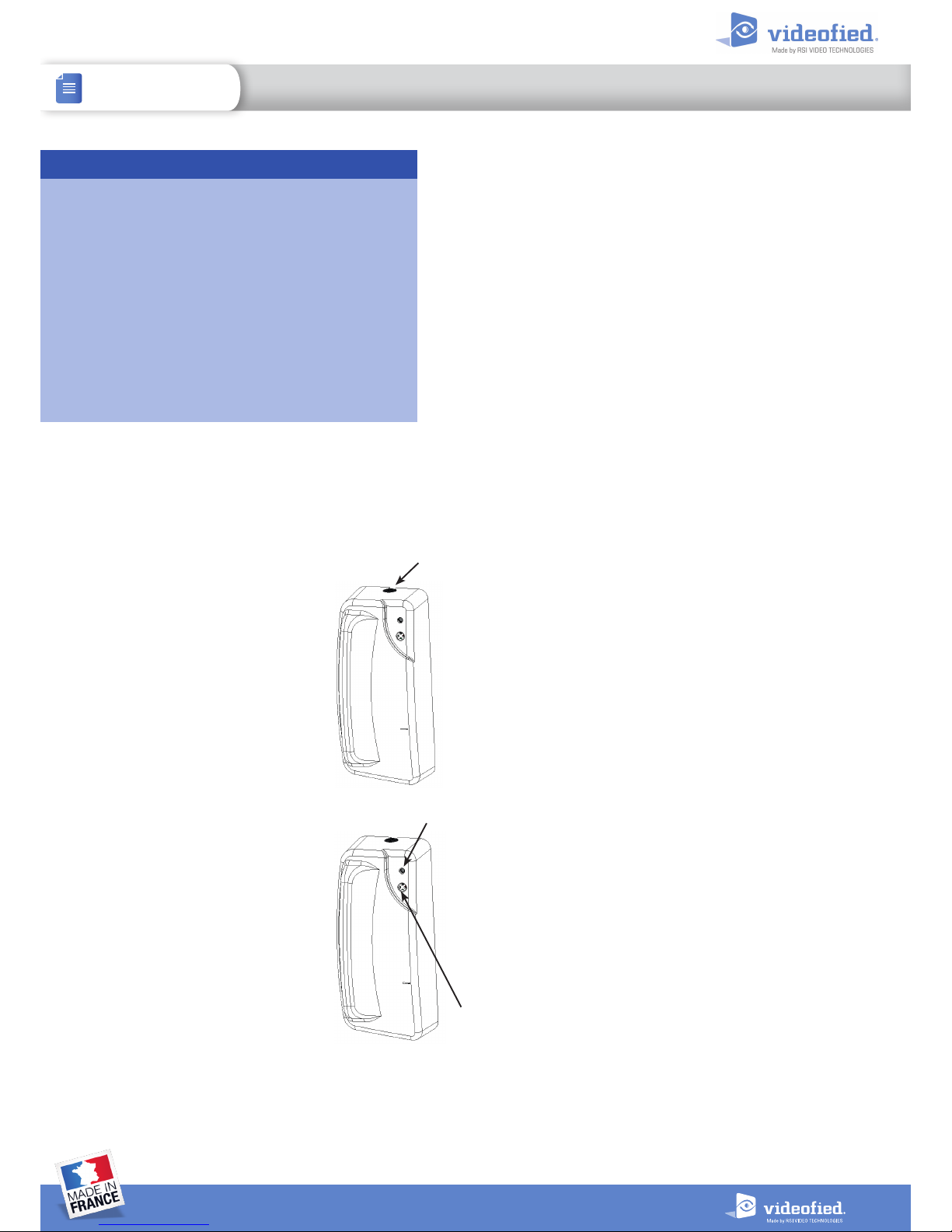
6 Using a paperclip, press and release
the contact INIT button.
The contact LED flashes. Wait for the
keypad to display DETECTOR (1-24)
RECORDED.
7 Press YES/OK. The display shows
RADIO RANGE TEST?
Press YES/OK again. The detector LED
starts flashing and keypad display shows
TEST IN PROGRESS.
8 Take the detector to its intended
mounting location and make sure that
the LED flashes continuously, indicating
good communication with the control
panel.
9 Press YES/OK to end the radio range test then press ESC
NO.
10 The display shows AREA ASSIGNMENT AREA: 1. Press either
arrow button repeatedly until desired AREA number appears,
then press YES/OK.
11 The display shows PERIMETER DEVICE?
Press YES/OK or ESC NO, whichever is appropriate for this
device (a device configured as PERIMETER will be armed for
the “E” and perimeter special arming modes, only contacts
protecting the external accesses should be configured for
perimeter arming).
12 The display shows NAME + LOCATION:
Enter appropriate device name/location (up to 16 characters),
then press YES/OK. The display shows the device number and
name for confirmation.
13 Press YES/OK. The display shows:
FUNCTIONAL DEVICE TEST?
Caution: the panel records the current state of the detector
and the current state of the wired input as being the normal
state at the beginninfg of the functional device test :
• The door contact must be closed at the beginning of the
detection test to be configured as Normally Closed NC.
• If the wired input is open when recorded, it will be
configured as Normally Open NO(and conversely).
That setting cannot be changed unless the contact is
deleted from the panel programming and recorded again.
Press YES/OK again and verif y detector operation. For example,
move the magnet next to the detector to make the LED go off,
then move the magnet away from detector to make LED turn on
indicating detection.
14 Press YES/OK to end detection verification.
15 The display shows ENTERING A NEW DEVICE?
Repeat steps 1 - 14 for remaining detectors.
Screw
LED
INIT button
UNIVERSAL DOOR CONTACT CT201 CT601 CT702
INSTALLATION SHEET
DOC. - REF. 219-CT
MODIF. DATE : AUGUST 2016
VERSION : XX.XX.XX
1
Page 2
Mounting procedure
> Use proper tools and hardware.
> To prevent false triggering the magnet must be aligned with
the upper part of the contact, following the markings. Use the
plastic adapters to align the magnet.
> The magnet must always be mounted on the mobile part
(door).
Note: do not install the contact and its magnet on a ferromagnetic
support
> The distance between the magnet and the contact must be
lower than 1 cm.
> Install that device indoors with a controllled temperature.
Note: if only the wired input is used, installing the magnet is not
needed.
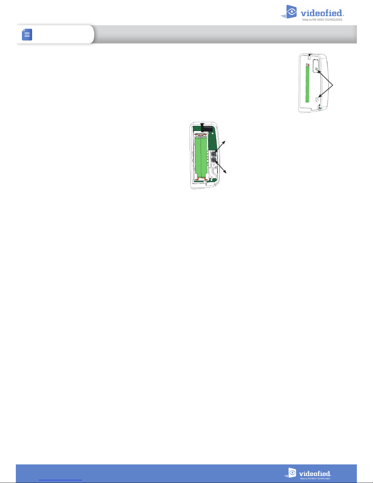
1 Remove the base from the contact.
2 Hold the base against the wall and
mark the mounting points.
3 Drill.
4 Mount the base on the wall.
5 If using the wired input,
connect 2 AWG22 wires from
the wired detector to the input
terminals.
6 Mount the detector on its base
and lock with the screw.
7 Insert the magnet in its case.
8 Use the plastic parts to place
the magnet next to the detector.
9 Hold the magnet base against the wall and mark the
mounting points.
10 Drill.
11 Fix the mounting with the appropriate screw
s.
Mounting
brackets
Connect to the
wired detector
terminals
2
UNIVERSAL DOOR CONTACT CT201 CT601 CT702
INSTALLATION SHEET
Page 3
3
UNIVERSAL DOOR CONTACT CT201 CT601 CT702
INSTALLATION SHEET
Security notes / (FR) Notes de sécurité / (DE) Hinweise zur Sicherheit
Français
• Retirez les piles avant toute opération de
maintenance !
• Attention ! Il y a un ris que d'explosion si la bat terie
utilisée est remplacée par un mauvais modèle !
• Respectez la polarité lors de la mise en place des
piles !
• Ne jetez pas les batteries usagées !
Ramenez-les à votre installateur ou à un point de
collecte spécialisé.
English
• Remove the batteries before any
maintenance !
• WARNING, there is a risk of explosion if a battery
is replaced by an improper model !
• Observe polarity when setting up the batteries!
• Do not litter the bat teries when they are used!
Dispose of them properly according to Lithium
Metal requirements
Deutsch
• Batterien vor jeglichen Wartungsarbeiten
entfernen!
• Vorsicht, es besteht Explosionsgefahr, wenn eine
Batterie durch eine Batterie falschen Models
ersetzt wird!
• Achten Sie beim Einsetzen der Batterien auf die
Polun g!
• Entsorgen Sie Batterien nicht im normalen
Haushaltsmüll! Bringen Sie Ihre verbrauchten
Batterien zu den öffentlichen Sammelstellen.
FCC Regulatory Information for USA and CANADA
FCC Part 15.21 Changes or modific ations made to this equipm ent not expressly ap proved by RSI Video Technologies m ay void the FCC authorization
to operate this equipment.
FCC Part 15.105 Class B
This equipment has been tested and found to comply with the limits for a Class B digital device, pursuant to Part 15 of the FCC Rules. These limits
are designed to provide reasonable protection against harmful interference in a residential installation. This equipment generates, uses and
can radiate radio frequency energy and, if not installed and used in accordance with the instructions, may cause harmful interference to radio
communications. However, there is no guarantee that interference will not occur in a particular installation. If this equipment does cause harmful
interfe rence to radio or television r eception, which can be deter mined by turning the equipme nt off and on, the user is encoura ged to try to correct
the interference by one or more of the following measures:
>
Reorient or relocate the receiving antenna.
>
Increase the separation between the equipment and receiver.
>
Connect the equipment into an outlet on a circuit different from that to which the receiver is connected.
>
Consult the dealer or an experienced radio/TV technician for help.
Radio frequency radiation exposure information according 2.1091 / 2.1093 / OET bulletin 65
This equipment complies with FCC radiation exposure limits set forth for an uncontrolled environment. This equipment should be installed and
operated with minimum distance of 20 cm between the radiator and your body.
Cet équipement est conforme aux limites d’exposition aux rayonnements IC établies pour un environnement non contrôlé.
Cet équipement doit être installé et utilisé avec un minimum de 20 cm de distance entre la source de rayonnement et votre corps.
This transmit ter must not be co-located or operating in conjunction with any other antenna or transmitter.
This device complies with Part 15 of the FCC Rules and with Industry Canada licence-exempt RSS standard(s)
Operation is subject to the following two conditions:
1
This device may not cause harmful interference, and
2
This device must accept any interference received, including interference that may cause undesired operation.
Le présent appareil est conforme aux CNR d’Industrie Canada applicables aux appareils radio exempts de licence.
L’exploitation est autorisée aux deux conditions suivantes :
1
L’appareil ne doit pas produire de brouillage, et
2
L’utilisateur de l’appareil doit accepter tout brouillage radioélectrique subi, même si le brouillage est susceptible d’en compromettre le
fonctionnement.
Page 4
EMEA SALES
23, avenue du Général Leclerc
92340 BOURG-LA-REINE
FRANCE
E-Mail : [email protected]
North American Headquarters
1375 Willow Lake Blvd, Suite 103
Vadnais Heights, MN 55110
USA
E-Mail : [email protected]
4
www.videofied.com
UNIVERSAL DOOR CONTACT CT201 CT601 CT702
INSTALLATION SHEET
The EC declaration of conformity of
this product is available by flashing
that QR code :
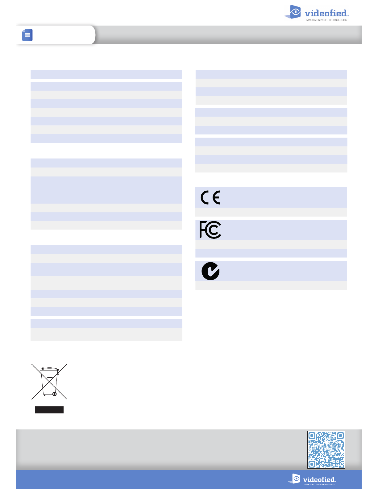
Battery
Type C - LS14500 SAFT - Lithium battery
Nominal voltage
3 V
Low battery limit
2.7 V
Estimated battery life
Up to 4 years
Current consumption
Standby (1h average)
30 µA
Max
70 mA (with alarm and communication)
Panel compatibility
W, X and VISIO panels
ELECTRICAL PROPERTIES
RF S2View® technology
Radio type
Spread spectrum RF bidirectional
Operating frequency
• 868MHz - CT201 (Europe, Africa, Asia)
• 915MHz - CT601 (Americas)
• 920MHz - CT702 (Australia, Chile, Peru, Paraguay)
Transmission security
AES algorithm encryption
Supervision
Radio, batteries, tamper
Radio antenna
Integrated
RADIO PROPERTIES
Internal detection
I.L.S with provided Alnico magnet
Axis of detection
3 axis (X, Y, Z)
Opening detection distance
2.3 cm (axis Y & Z)
1.4 cm (axis X )
Closing detection distance
2 cm (axis Y & Z)
1.2 cm (axis X )
External detection
Wired input
Max wire length
16m
Input type
NC or NO (recorded during detection test)
DETECTION PROPERTIES
BOX
Physical properties
Material
ABS UL94-V0
Dimensions
79.3 mm x 35 mm x 24.6 mm
Weight
32 g (without battery)
Installation / Mounting
Mounting support Non-ferromagnetic surface (ex : wood)
Wall mounting 2 screws
Box sealing 1 screw
Environmental properties
Operating temperature
-10°/+55°C
Max relative humidity
75%, without condensing
This symbol on the product or on its packaging indicates that this product should not be treated as household waste.
It must be handed over to the applicable collection point for the recycling of electrical and electronic equipment.
By ensuring this product is disposed of correctly, you will help prevent potential negative consequences for the
environment and human health. The recycling of materials will help to conserve natural resources.
For more information about recycling of this product, please contact your local municipality, your waste disposal
service or the company that installed the product.
STANDARDS AND CERTIFICATIONS
868MHz (CT 201)
Compliant with the annex IV of the R&TTE Directive 1999/5/EC
915M Hz (C T 601)
USA FCC
Part 15C
Canada IC
RSS-247 Issue 1
920MHz (CT 702)
Australia RCM
AS/NZS4268
Tamper
Tamper detection
Cover and wall tamper
 Loading...