

Videofied BR250, BR651, BR752 Installation Sheet
INSTALLATION SHEET
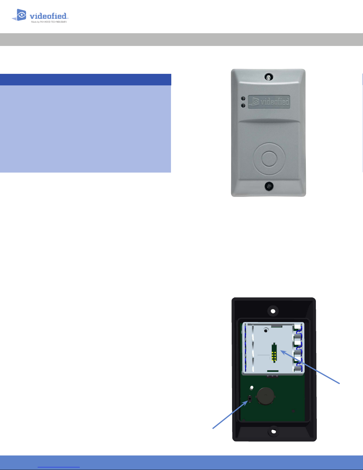
Product presentation
The BR badge reader is designed to be used within a
Videofied™ alarm system.
Its main features are :
• Interactive wireless technology.
• Dual tamper function.
• Transmits check-in/status signals every 8 minutes
• Lithium bat teries : 4 years lifespan.
• Mobility-Use outdoors or indoors with a fully
weatherproof casing withstanding temperatures
from -25°C to +70°C (-13°/158°F ).
Installation and Programming
BR250/651/752 Badge Reader
Doc. - Ref. 218-BR
Version : November 2016
The following provides summarized steps for device programming
and testing.
Mount the base to the wall observing the “TOP” marking.
1
Insert 3.6V DC LS14500 Lithium batteries observing correct
2
po larit y.
With the programming keypad, browse to the ADD A NEW
3
DEVICE menu (Level 4).
Press OK/YES. The keypad displays PRESS PROGRAM BUTTON
4
OF DEVICE.
Press program button. The button blinks in green. Wait for
5
keypad to display BADGE READER n RECORDED.
Press OK/YES. The display shows RADIO RANGE TEST?
6
Press OK/YES again to run the test. The keypad display shows
7
TEST IN PROGRESS.
Please make sure the top LED blinks in red, indicating good
8
communication with the control panel. The test result must stabilize at
8/9 as a minimum.
If the radio range level is below 8/9, change the location of the
detector to obtain satisfactory radio range level.
Press OK/YES to end the radio range test then ESC NO.
9
Choose a zone for that badge reader (by default that zone will be
10
delayed ) and name it.
The keypad displays OPERATION COMPLETED ? Mount the
11
badge reader on its base and press OK/YES.
Installation guidelines
RF testing will ensure good communication between the
control panel and all system devices. Install the badge reader
and other system devices in the order of the following steps :
Program the badge reader and all other devices into the
>
control panel and test RF communication from each intended
device location to the control panel.
Mount the badge reader at the final location.
>
Battery
Case
Name the detector. When finished, keep ESC NO pressed to exit
12
from configuration mode.
For full programming details, please refer to the control panel
installation manual.
www.videofied.com
INIT
Button
BR250/651/752 Badge Reader
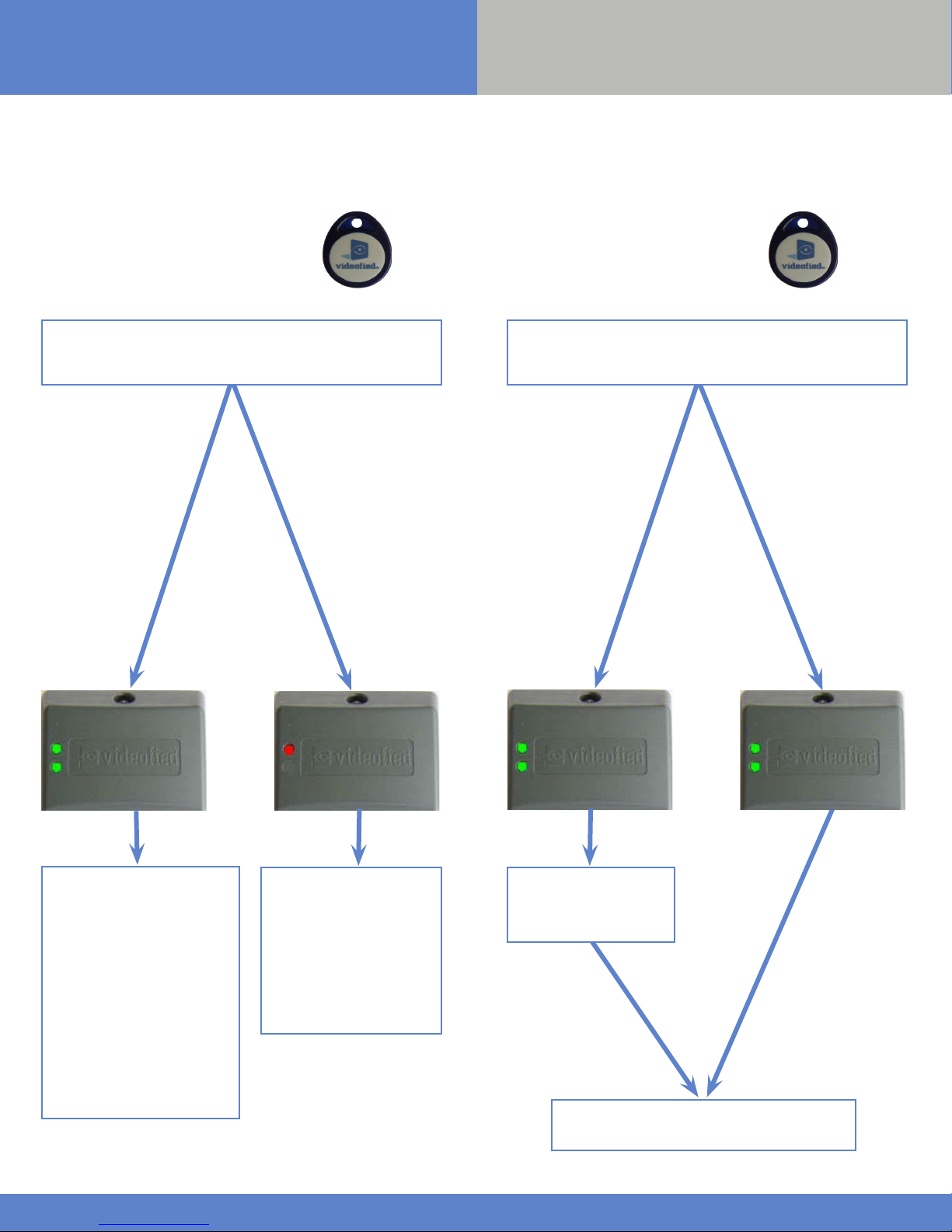
Functioning of indicators
IN S TA LLATI O N SHEE T
During arming
When reading the badge, the reader emit s a beep, then two
beeps indicating the badge has been accepted. The LED
indicators of the reader are going to indicate a message:
Problem was
identified during
the incomplete
arming (detection
in and instant area)
Everything is fine :
System is arming
During disarming
When reading the badge, the reader emit s a beep, then two
beeps indicating the badge has been accepted. The LED
indicators of the reader are going to indicate a message:
An alarm
triggered on
The top indicator
flashes green for
2s, and that of the
bottom flashes
fixed green light
and the reader
beeps 4 times
There was no alarm
The two indicators
remain on with
fixed green light
for 5 seconds
The LEDs will stay
on for 5 seconds
The arming stops.
The two indicators flash
green for 5s then turn off: A
fault was detected.
In order to know more
about what happened a
keypad is required.
Without action from the
user, arming will start
again aer 3 min and the
concerned detector will be
bypassed from this arming.
Flashing of the top red
indicator (only) every
second during arming
de lay.
The top red indicator
flashes every two
seconds indicating that
the system is armed.
Verify with a keypad
in order to know more
about what happened
www.videofied.com
The two indicators turn off, the system is
disarmed.
2
 Loading...