

Page 1
PIX-LR
Audio Interface for the PIX-E Series
User Guide
Page 2

Legal Notices
Manual Conventions
Product specications and features are subject to
change without prior notication.
Copyright © 2016
Sound Devices, LLC
All rights reserved
This product is subject to the terms and conditions
of a software license agreement provided with the
product, and may be used in accordance with the
license agreement.
This document is protected under copyright law. An
authorized licensee of this product may reproduce
this publication for the licensee’s own personal use.
This document may not be reproduced or distributed,
in whole or in part, for commercial purposes, such
as selling copies or providing educational services or
support.
This document is supplied as a technical guide. Special
care has been taken in preparing the information for
publication; however, since product specications
are subject to change, this document might contain
omissions and technical or typographical inaccuracies.
Sound Devices, LLC does not accept responsibility
for any losses due to the use of this guide.
Trademarks
Symbol Description
>
+
i
⚠
This symbol is used to show the order in
which you select menu commands and
sub-options, such as: System > Version
Info indicates you use the Control knob
to navigate the Main menu and select
System followed by Version Info.
A plus sign is used to show button or
keystroke combinations.
For instance, ALT+MENU means to hold
the ALT button down as you press the
MENU button. Ctrl+V means to hold the
Control key down and press the V key
simultaneously.
A note provides recommendations and
important related information. The
text for notes also appear italicized in
a different color.
A cautionary warning about a specic
action that could cause harm to you,
the device, or cause you to lose data.
Follow the guidelines in this document
or on the unit itself when handling electrical equipment. The text for cautionary notes also appear bold and italicized
in a different color.
The “wave” logo and USBPre are registered trademarks, and FileSafe, PowerSafe, Wave Agent, and
PIX-Assist are trademarks of Sound Devices, LLC.
Mac and OS X are trademarks of Apple Inc.,
registered in the U.S. and other countries. Windows
is a registered trademark of Microsoft Corporation
in the United States and other countries. Gorilla is a
registered trademark of Corning Incorporated.
www.sounddevices.com
support@sounddevices.com
PIX-LR User Guide • Rev 2-A • March 11, 2016
This document is distributed by Sound Devices, LLC
in PDF format only. E-published in the USA.
Sound Devices, LLC
E7556 Road 23 and 33
Reedsburg, Wisconsin USA
+1 (608) 524-0625
Toll Free: (800) 505-0625
Fax: +1 (608) 524-0655
Page 3

Revision History
This table provides the revision history of this guide.
Rev# Date Firmware
Version
2-A March 2016 v2.00 Preliminary Draft; Initial Ofcial Publication
Description
3
Page 4

User Guide
4
Page 5

Table of Contents
PIX-LR Audio Interface 7
Front Panel ......................................7
Top Panel .......................................8
Back Panel ......................................9
Assigning Audio Input Sources to XLR ...............9
Modifying Audio Settings ........................10
Audio Screen Differences with PIX-LR ..............12
Adjusting Gain with the PIX-LR ....................12
Choosing a Headphone Source ....................14
Adjusting PIX-LR LED Brightness ...................15
Specifications ...................................15
Declaration of Conformity ........................16
5
Page 6

User Guide
6
Page 7

PIX-LR Audio Interface
The PIX-LR is an accessory that provides
the PIX-E Series with two XLR inputs, two
XLR outputs, accurate LED metering, and
dedicated transport and gain controls.
The mic preamps within the PIX-LR are
some of the highest-quality preamps
available, and the same preamps for
which Sound Devices, LLC is worldfamous. These active-balanced preamps
are sonically pure with extremely low selfnoise, high headroom, and low distortion.
They also include excellent input limiters,
which keep the input from overloading,
even with unexpected loud noises or
shouting right into the microphones. And
they include full-spec 48 V phantom for
high-quality condenser mics and low-cut
lters to cut wind noise and room rumble.
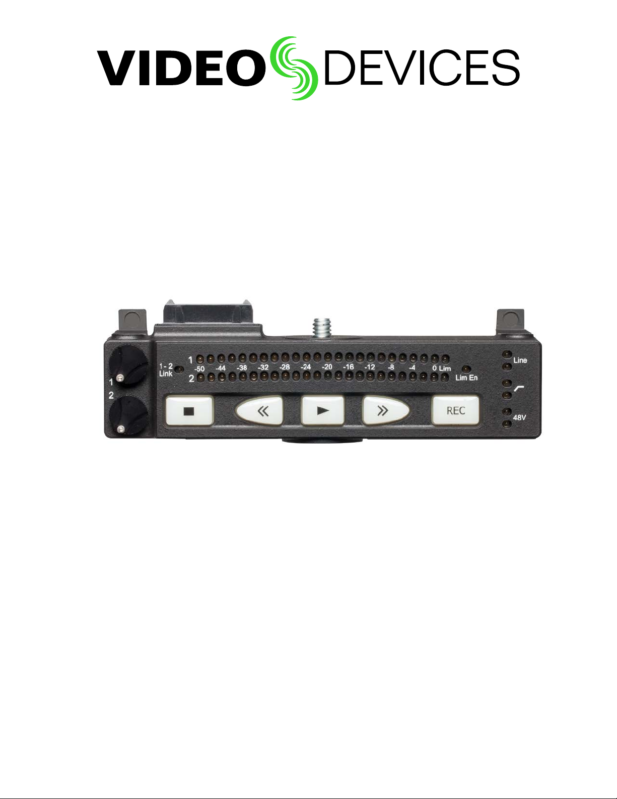
Front Panel
Topics in this section include:
Front Panel
Top Panel
Back Panel
Assigning Audio Input Sources to XLR
Modifying Audio Settings
Audio Screen Differences with PIX-LR
Adjusting Gain with the PIX-LR
Choosing a Headphone Source
Adjusting PIX-LR LED Brightness
Specifications
Declaration of Conformity
The front panel has the following features:
Gain
Control 1
Gain
Control 2
1-2
Link
Metering
LEDs
Transport
Controls
Activity
Limiter LEDs
Limiter
Enabled
Low-cut
Filter LEDs
Line-level
LEDs
Phantom
Power LEDs
7
Page 8

User Guide
Feature Description
Transport Controls Five large, backlit buttons for transport controls: Stop, Rewind, Play,
Gain Controls (1-2) Two dedicated gain controls for XLR inputs 1 and 2.
1-2 Link LED Indicates when XLR inputs 1 and 2 are a linked stereo pair.
Metering LEDs Track metering LEDs
Active Limiter LEDs Illuminates when limiting occurs.
Limiter Enabled LED Illuminates when limiter is enabled.
Line LEDs Illuminates when XLR inputs are set to line level; Off when set to
High-Pass Filter LEDs Illuminates when the low-cut lter is enabled for the XLR input(s)
Phantom LEDs Illuminates when phantom power (48 V) is active for the input(s).
Top Panel
The top panel provides the multi-pin connector and mounting screw used to
connect the accessory to the bottom panel of PIX-E monitors.
Fast Forward, and Record.
Gain range for both XLR inputs is -∞ to +72 dB.
Mic.
Multi-pin
Connector
Mounting
Screw
i The PIX-LR attaches to the bottom panel of PIX-E monitors. Sound Devices, LLC
recommends, as a best practice, the monitor’s power be turned off and unplugged before
afxing the accessory. Further instructions for attaching the PIX-LR to your monitor is
provided in the PIX-LR Quick Start Guide, which is shipped with the accessory. It is also
available as a free PDF download from the Video Devices website.
8
Page 9

Back Panel
The back panel has the following connectors:
Feature Description
Mic/Line Two XLR connectors for active-balanced, analog microphone- or
Line Out Two standard, 3-pin XLR connectors for balanced, line-level analog
Mic/Line In
(1 & 2)
PIX-LR AUDIO INTERFACE
Line Out
(1 & 2)
line-level inputs (1 and 2). [Pin-1 ground; pin-2 (+); pin-3 (-).]
outputs. [Pin-1 ground; pin-2 hot (+); pin-3 cold (-).]
In addition to their use as normal balanced outputs, the XLR outputs
may also be connected as unbalanced. When doing so, connect pin 1
to ground, pin 2 to signal, and leave pin 3 unconnected.
Assigning Audio Input Sources to XLR
When the PIX-LR is attached, both XLR 1 and XLR 2 options become viable
audio sources for the PIX-E monitor.
To set the audio input source to the PIX-LR inputs:
1. Press the Audio soft key button to access the Audio screen.
1. Use the Control knob to select the track to adjust.
2. Turn and press the Control knob to select the track’s Source eld.
3. Set the input source to XLR 1 or XLR 2.
i The Audio screen is slightly different when the PIX-LR is attached. For more
information, see Audio Screen Differences with PIX-LR.
9
Page 10

User Guide
Modifying Audio Settings
When the PIX-LR is attached to a PIX-E monitor, additional settings become
available via the monitor’s Audio submenu.
To modify the Audio submenu’s PIX-LR settings:
1. Press the MENU button to view the Main menu.
2. Select Audio and adjust settings as needed.
The settings associated with the PIX-LR are:
setting Description
XLR 1 Input Sets input type for XLR 1. Default is Line. Options include: Line,
XLR 2 Input Sets input type for XLR 2. Default is Line. Options include: Line,
XLR 1 Input Low Cut Sets low cut frequency for analog XLR input 1. Options include:
XLR 2 Input Low Cut Sets low cut frequency for analog XLR input 2. Options include:
Mic, Line 48V Phantom, Mic 48V Phantom
Mic, Line 48V Phantom, Mic 48V Phantom
The default setting for both inputs is Mic.
i 48 V phantom is needed to power many professional condenser
microphones. If using professional dynamic microphones, 48 V
phantom is not needed and can be turned off.
Off, 40 Hz, 80 Hz, 120 Hz, 160 Hz, 200 Hz, or 240 Hz
Off, 40 Hz, 80 Hz, 120 Hz, 160 Hz, 200 Hz, or 240 Hz
Input Low Cut settings for both XLR inputs are off by default.
i The low cut lter removes low-frequency bass sound, such as
wind noise or room rumble, to make microphones sound better.
If the input sounds too “rumbly,” turn on the low-cut lter to the
lowest number needed to make the input sound better.
XLR Input Linking Selects whether the input levels are controlled independently
(unlinked) or as a stereo pair (linked). Options include: Off, 1-2
Linked without Pan, and 1-2 Linked with Pan. Linking is off by
default.
For more information, see Adjusting Gain with the PIX-LR.
i Limiters are linked and will act together.
XLR Input Limiter Turns XLR input limiter on or off. Limiter is on by default.
A limiter quickly and automatically turns an input down momentarily, just enough to keep the input from overloading and
sounding very distorted. This automatic gain-reduction happens
only during the overload, and otherwise does not affect the incoming signal.
i Sound Devices, LLC recommends always keeping the limiter
turned on.
10
Page 11

PIX-LR AUDIO INTERFACE
setting Description
XLR Output Source Sets the XLR output source. Options include:
• XLR Input 1,2
• Tracks 1,2
• Tracks 3,4
• Tracks 5,6
• Tracks 7,8
• All tracks summed - mono
• All tracks summed - stereo
When set to All tracks summed - mono, all tracks (12345678) go
to both 1 and 2.
When set to All tracks summed - stereo, odd tracks (1357) go to
1 and even tracks (2468) go to 2. By default, the source is set to
All tracks summed - stereo.
The source chosen for this setting is displayed on the monitor’s
Audio screen. For instance, when set to the default of All tracks
summed - stereo, the Audio screen displays XLR Out: Tracks
1357, 2468 in the upper right corner.
i When XLR Input 1,2 is chosen as the output source, then XLR 1,2
is used while recording. During playback, however, the source
used is Tracks 1,2. Once playback is stopped, the output source
reverts back XLR Input 1, 2.
XLR Output Attenuation Adjusts output attenuation in 1db increments: 0 to -20dB, Off
XLR output attenuation is set to 0 dB by default.
PIX-LR LED Meters Sets the PIX-LR LEDs to meter specied pairs. Options include:
• Tracks 1 & 2
• Tracks 3 & 4
• Tracks 5 & 6
• Tracks 7 & 8
• XLR 1 & 2
By default, LED metering is set to XLR 1 & 2.
i When XLR 1 & 2 is chosen for LED metering, then metering of
XLR inputs 1 and 2 is used while recording. During playback,
however, the LEDs show the metering of Tracks 1 and 2. Once
playback is stopped, LED metering reverts back to XLR 1 & 2.
11
Page 12

User Guide
Track’s Audio
Source set to
PIX-LR Inputs
XLR output source
Input gain is grayed out;
Adjust only from PIX-LR
Highlight
Audio Screen Differences with PIX-LR
The PIX-E monitor’s Audio screen differs slightly whenever a PIX-LR is attached.
For instance, when the audio input source for any track is set to XLR 1 or XLR 2,
the corresponding elds in the Gain column can no longer be selected by using
the monitor’s Control knob. Additionally, after the XLR Output Source is set, the
chosen source is displayed in the upper right corner of the Audio screen.
Levels shown in the Gain column of the Audio screen are normally adjusted with
the Control knob, but when a track’s audio source is set to XLR inputs, level adjustment is transferred to the PIX-LR’s rotary gain controls. Therefore, the elds
in the Gain column become disabled (grayed out) and are no longer adjustable
from the Audio screen, using the Control knob. Although disabled, the elds in
the Gain column still display present levels and any adjustments as they are
made from the PIX-LR. This is particularly useful when XLR Input Linking with
or without Pan is enabled, because the Audio screen shows the changes in gain
levels while adjusting overall levels or the balance between inputs.
Adjusting Gain with the PIX-LR
With the PIX-LR attached and a track’s audio source set to an XLR input,
manual adjustment of gain levels is transferred to the PIX-LR’s rotary gain
controls.
For instance, if the source for Track 01 is set to XLR 1 and Track 02 is set to XLR
2, then turning gain control 1 adjusts levels for Track 01 on XLR 1, while turning
gain control 2 adjusts levels for Track 02 on XLR 2.
12
This functionality changes, however, when Input Linking is enabled, which
may be set with or without pan. When enabled, the linkage is indicated by the
amber illumination of the 1-2 Link LED on the front panel of the PIX-LR, and the
gain controls operate differently depending on whether pan is included in the
conguration.
Page 13

PIX-LR AUDIO INTERFACE
see DeMo ViDeo
Audio Screen on PIX-E
PIX-LR: Gain Control 1
PIX-LR: Gain Control 2
(Disabled)
1-2 Link LED
(Amber)
Audio Screen (partial)
Counter-clockwise
Clockwise
As shown in the previous illustration, when linking is set to 1-2 Linked without
Pan, gain control 1 adjusts the overall gain level of both XLR inputs, while gain
control 2 is disabled.
When linking is set to 1-2 Linked with Pan, gain control 1 still adjusts the overall level of both XLR inputs, but gain control 2 adjusts the balance between the
inputs, as shown in the next illustration.
• Turning gain control 2 counter-clockwise fully attenuates XLR input 2.
• Turning gain control 2 clockwise fully attenuates XLR input 1.
Equal balance of the two inputs is achieved by setting the controls to center
position.
13
Page 14
User Guide
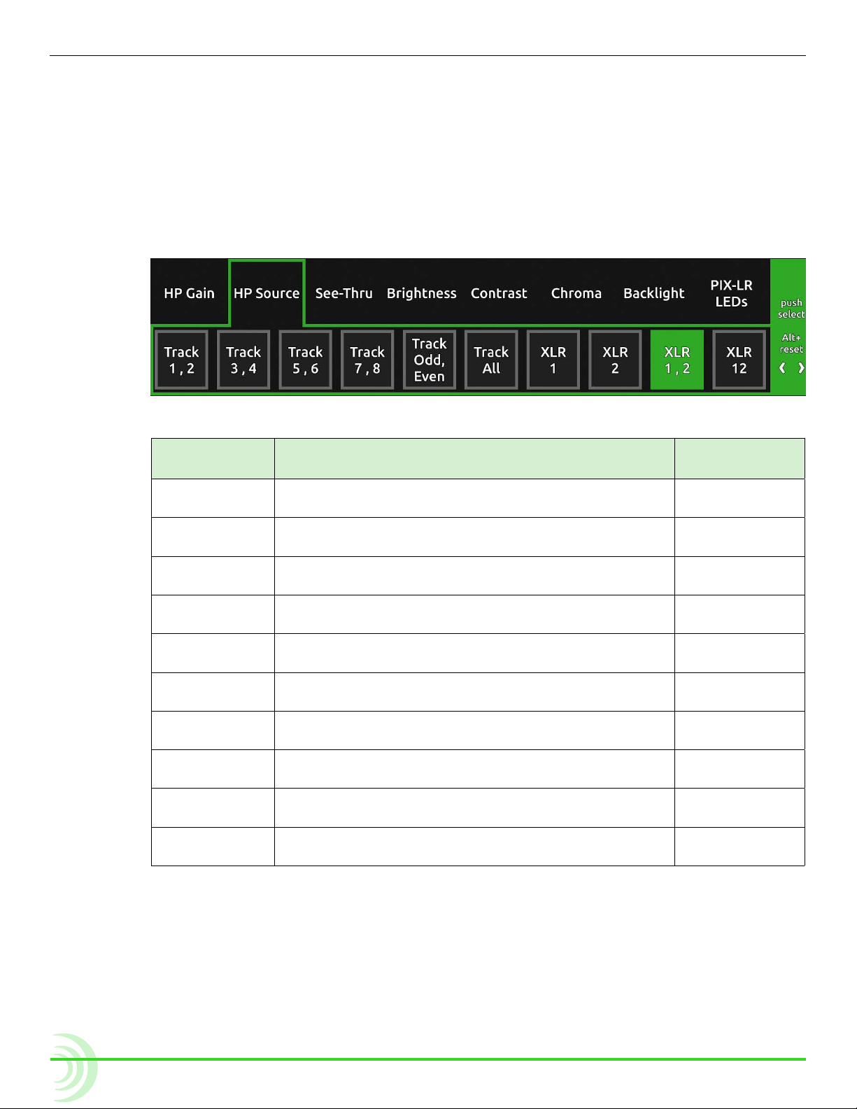
Choosing a Headphone Source
Every PIX-E monitor features a 3.5 mm headphone output. The audio source for
this output is user-denable. When the PIX-LR is attached, existing options are
slightly renamed and four new options appear.
To choose a headphone source:
1. Press and hold the MENU button for 1 second to access the Monitor menu.
2. Use the Control knob to select the HP Source tab.
3. Select a headphone source.
source with
Description source naMe
piX-Lr
Track 1,2 Select this stereo option for routing channel 1 to the
left and 2 to the right.
Track 3,4 Select this stereo option for routing channel 3 to the
left and 4 to the right.
Track 5,6 Select this stereo option for routing channel 5 to the
left and 6 to the right.
Track 7,8 Select this stereo option for routing channel 7 to the
left and 8 to the right.
Track Odd,
Even
Track All Select this mono option if you want all audio inputs
XLR 1 Select this option for routing XLR 1 to both sides of
XLR 2 Select this option for routing XLR 2 to both sides of
XLR 1,2 Select this stereo option for routing XLR 1 to the left
XLR 12 Select this mono option if you want both XLR inputs
Select this stereo option for routing odd channels to
the left and even channels to the right.
routed to both sides of headphones.
headphones.
headphones.
and XLR 2 to the right.
routed to both sides of headphones.
w/o piX-Lr
1,2
3,4
5,6
7,8
1357,2468
12345678
14
The XLR source options provide a low-latency path to the headphone
monitor and to the XLR outputs. When monitoring track sources on
headphones or the XLR outputs, the track audio is delayed to match the
displayed video.
i When HP Source is set to any of the XLR options, playback temporarily switches
the source for headphone monitoring to Track 1,2. After playback is stopped, the
source reverts back to the actual XLR option selected.
Page 15

Adjusting PIX-LR LED Brightness
When the PIX-LR is attached to a PIX-E monitor, an additional setting becomes
available in the Monitor menu. Called PIX-LR LEDs, this setting may be used to
adjust the brightness of the accessory’s LEDs as well as its back-lit transport
controls.
To adjust PIX-LR LED brightness:
1. Press and hold the MENU button for 1 second. The Monitor menu appears
superimposed over the lower portion of the screen.
2. Select the PIX-LR LEDs tab and then adjust the level of brightness from 0%
(off) to 100%. By default, the brightness level is set to 70%.
Specifications
The following specications apply to the PIX-LR.
naMe Description
Power Powered by the monitor.
Frequency response 10 Hz - 20 kHz +0,-0.5 dB re 1 kHz
THD+N 0.05% max (20-20kHz lter), 0dBu in, gain +12 dB
Max Gain (mic position) +72 dB (dBu in to -20dBFS)
Gain (line position) +45 dB (dBu in to -20dBFS)
Max input level
(mic position)
Max input level
(line position)
Equivalent input noise
(mic position)
Max line output level +18 dBu (2k load)
Input limiters 40 dB range, 20:1 ratio, 1 mS attack, 200 mS release
Low cut lters Selectable frequency, 12 dB/oct
48 V phantom Full 10 mA each
XLR wiring
(in and out)
XLR protection
(in and out)
Size (H x W x D) · 1.3 in x 5.4 in x 2.1 in
Weight · 8.0 oz
+8 dBu (gain at +12 dB)
+26 dBu (gain at +12 dB)
-128 dBu (A-weighted)
Pin 2 = hot, pin 3 = cold, pin 1 = ground
To drive unbalanced source from output, only use pins 2 and 1; leave
pin 3 disconnected.
Protected against 48V phantom, shorts, and fully RF-ltered
· 3.3 cm x 13.7 cm x 5.3 cm
· 0.23 kg
PIX-LR AUDIO INTERFACE
15
Page 16

User Guide
Declaration of Conformity
Declaration of Conformity
According to EN ISO/IEC 17050-1:2004
Manufacturer’s Name: Sound Devices, LLC
Manufacturer’s Address: E7556 State Road 23 and 33
Reedsburg, WI 53959 USA
Declares under sole responsibility that the product as delivered
Series: PIX-E Recording Field Monitors
Model Number: PIX-LR (Audio Interface Accessory for the PIX-E Series)
Product Options: This declaration covers all options of the above product
complies with the essential requirements of the following applicable European
Directives, and carries the CE marking accordingly:
EMC Directive (2004/108/EC)
EN 55022:2005
EN 55103-2:2009
RoHS Directive (2011/65/EU)
WEEE Directive (2012/19/EU)
First date of CE approval December 23, 2015.
This Declaration of Conformity applies to the above-listed product(s) placed on the EU
market after:
December 23, 2015
Date Matt Anderson
President
16
Page 17

®
Sound Devices, LLC
E7556 Road 23 and 33
Reedsburg, Wisconsin 53959
USA
Phone: +1 (608) 524-0625
Fax: +1 (608) 524-0655
Customer Support
Toll Free: (800) 505-0625
support@sounddevices.com
http://www.sounddevices.com/support
http://forum.sounddevices.com
Product Information
For more information about products
and accessories, visit us on the web
at www.sounddevices.com.
 Loading...