

Page 1

PIX-E5 / PIX-E5H
Recording Field Monitor
User Guide
Page 2

Legal Notices
Manual Conventions
Product specications and features are subject to
change without prior notication.
Copyright © 2015
Sound Devices, LLC.
All rights reserved.
This product is subject to the terms and conditions
of a software license agreement provided with the
product, and may be used in accordance with the
license agreement.
This document is protected under copyright law. An
authorized licensee of this product may reproduce
this publication for the licensee’s own personal use.
This document may not be reproduced or distributed,
in whole or in part, for commercial purposes, such
as selling copies or providing educational services or
support.
This document is supplied as a technical guide. Special
care has been taken in preparing the information for
publication; however, since product specications
are subject to change, this document might contain
omissions and technical or typographical inaccuracies.
Sound Devices, LLC does not accept responsibility
for any losses due to the user of this guide.
Trademarks
Symbol Description
>
+
i
⚠
This symbol is used to show the order in
which you select menu commands and
sub-options, such as: System > Version
Info indicates you use the Control knob
to navigate the Main menu and select
System followed by Version Info.
A plus sign is used to show button or
keystroke combinations.
For instance, ALT+MENU means to hold
the ALT button down as you press the
MENU button. Ctrl+V means to hold the
Control key down and press the V key
simultaneously.
A note provides recommendations and
important related information. The
text for notes also appear italicized in
a different color.
A cautionary warning about a specic
action that could cause harm to you,
the device, or cause you to lose data.
Follow the guidelines in this document
or on the unit itself when handling electrical equipment. The text for cautionary notes also appear bold and italicized
in a different color.
The “wave” logo and USBPre are registered trademarks, and FileSafe, PowerSafe, Wave Agent, and
PIX-Assist are trademarks of Sound Devices, LLC.
Apple is a registered trademark, and Mac and OS X
are trademarks of Apple Inc., registered in the
U.S. and other countries. Windows is a registered
trademark of Microsoft Corporation in the United
States and other countries. Gorilla is a registered
trademark of Corning Incorporated.
www.sounddevices.com
support@sounddevices.com
PIX-E5 User Guide • Rev 1-D • September 10, 2015
This document is distributed by Sound Devices, LLC
in PDF format only. E-published in the USA.
Sound Devices, LLC
E7556 Road 23 and 33
Reedsburg, Wisconsin USA
+1 (608) 524-0625
Toll Free: (800) 505-0625
Fax: +1 (608) 524-0655
Page 3

Revision History
This table provides the revision history of this guide, including cross-reference links to “what’s new”
and/or modied within the guide.
Rev# Date Firmware
Version
1-A July 2015 v1.00 Initial Ofcial Publication for PIX-E5 launch
1-B Aug 2015 v1.01/v1.02 Updates that addressed the 4K speckling and added one feature:
1-C Aug 2015 v1.03/v1.04 Updates for PIX-E5H product launch & feature enhancements:
1-D Sept 2015 v1.05 Update with feature enhancements:
Description
• File deletion - See “Deleting Recorded Files” on page 45
• HDMI Record Triggers - See “Setting up a Record Trigger” on
page 48
• Increased channels for HDMI I/O - See “Setting up Audio Input” on page 54 and “Routing Audio Output” on page 56
• QuickBoot Timer - See note in table located in “Top and Front
Panels” on page 7
• File List HH:MM:SS Duration - See “” on page 50
• LUTs - See “Using LUTs” on page 34
• Custom LUTs - See “Uploading Custom LUTs” on page 36
• HDMI Record Triggers for Panasonic - See “Setting up a Record
Trigger” on page 48
3
Page 4

User Guide
4
Page 5

Table of Contents
Overview of the Chassis 7
Top and Front Panels .............................7
Left Side Panel ...................................9
Menus and Navigation 13
Touch Screen and Tactile Controls .................13
Accessing the MAIN MENU Screen .................13
Toggling On-Screen Display Elements ..............14
Toggling Soft Key Button Functionality .............15
Monitor Soft Keys .............................16
PIX-Assist Monitoring Suite 21
Overview ......................................21
Assist Tools .....................................22
Using False Colors .............................22
Using Zebras .................................24
Using Zoom ..................................25
Using Peaking ................................27
Scopes .........................................29
Using the Waveform Monitor ...................29
Back and Bottom Panels .........................10
Right Side Panel ................................11
Record Soft Keys ..............................16
Using Soft Key Menus ...........................17
Configuring the On-Screen Display ................18
USB Keyboard ..................................19
Using the Vectorscope .........................31
Using the Histogram ..........................32
Using 4-Way Monitoring .........................33
Using LUTs .....................................34
Uploading Custom LUTs ........................36
Using Markers ..................................37
Resetting Monitor Defaults .......................40
Storage 41
SpeedDrive .....................................41
SD Memory Card ................................42
Metadata and File Name Format ..................42
File Name Formats ............................43
Formatting Storage Drives ........................44
Working with Files ..............................44
Deleting Recorded Files ........................45
Transferring Files to a Computer ................45
Recording and Playback 47
Record and Playback Icons ........................47
Recording ......................................47
Choosing a Video Input Source .................48
Setting up a Record Trigger ....................48
Selecting a Video Codec .......................49
Setting PsF Options ...........................49
FileSafe ......................................50
Viewing the File List ...........................51
Playing Back Recorded Files .......................51
Audio 53
Using the Audio Screen ..........................53
Setting up Audio Input ..........................54
Setting up Tracks ................................55
Routing Audio Output ...........................56
Adjusting Headphone Warning Bell Level ........57
Timecode 59
Setting a Timecode Mode ........................59
Toggling Drop Frame Timecode ...................60
Setting the Rec Run Timecode Value ...............60
System Functions 61
Time and Date ..................................61
Setting the Date and Time .....................62
Updating Firmware .............................62
Checking Version and Serial Number ...............63
Saving and Recalling Settings .....................63
Restoring Factory Default Settings .................64
5
Page 6

User Guide
Specifications 65
PIX-E5 Specifications .............................65
Video .......................................65
Audio .......................................66
Storage ......................................66
Timecode ....................................67
Power .......................................67
Physical ......................................67
Environmental ...............................67
PIX-E5H Specifications ...........................68
Video .......................................68
Audio .......................................68
Storage ......................................69
Timecode ....................................69
Power .......................................69
Physical ......................................69
Environmental ...............................69
6
Page 7

Overview of the Chassis
The PIX-E5 and PIX-E5H are specically
designed and built for the rigors of eld
production.
The chassis is made of high-strength,
thermally conductive aluminum. As
well as providing maximum durability,
the case doubles as a heat-sink,
providing excellent cooling of the inner
electronics.
By design, the PIX-E chassis gets very
warm, wicking away the heat from
the internal components. This design
ensures that the internal components
stay cool for years of trouble-free
operation in the most demanding
environments.
Top and Front Panels
Topics in this section include:
Top and Front Panels
Left Side Panel
Back and Bottom Panels
Right Side Panel
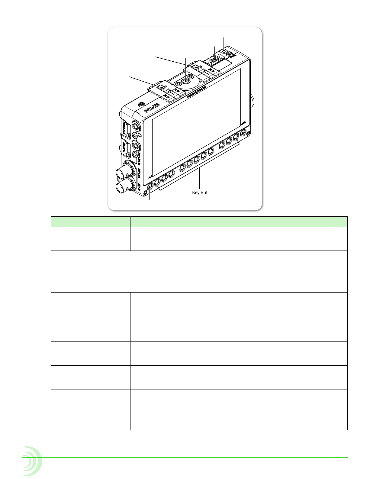
The top panel features the Power switch, a Power LED, a 1/4-inch, 20-threaded
mounting point, and two retainer clips used to secure batteries and the SpeedDrive to the back of the monitor.
The front panel has a sunlight-readable, 5-inch LCD that is protected behind an
alkali-aluminosilicate sheet of Gorilla® Glass 2, chemically strengthened to be
scratch- and impact-resistant.
Beneath the LCD is a row of buttons, which includes an ALT button on the left,
a MENU button on the right, and in between them, 11 multi-functional soft key
buttons.
7
Page 8
User Guide
ALT Button
Power Switch
Power LED
Mounting Point
Right
Retainer Clip
Soft Key Buttons
MENU Button
Left
Retainer Clip
LCD
Feature Description
Power Switch & LED Slide the Power switch to the right to turn on the device. While power
is on, the LED will illuminate green. When power is rst turned on, a
splash screen with the Video Devices logo will appear on the LCD.
i PIX-E monitors have a very powerful processor and operating system, so it takes up to 45 seconds
to boot the rst time. However, the QuickBoot™ feature reduces subsequent boot times to just a
few seconds. QuickBoot is enabled for two hours after powering down the monitor. Each time the
monitor is turned off, this timer is reset. During this time, boot times are reduced, but after two
hours, QuickBoot is deactivated and powering on the monitor will result in a normal, longer boot
process.
Retainer Clips The retainer clips snap into place to securely hold batteries and/or
Mounting Point Centered on the top and bottom panels, a 1/4-inch, 20 threaded,
LCD 5-inch LCD touch screen. 1920x1080 pixel resolution. Displays the
ALT Button Toggles alternative functions for the Soft Key buttons. It may be
MENU Button Displays the Main menu. May also be used to exit various screens.
the SpeedDrive™ to the back of the monitor. The right clip, labeled
with a battery icon, secures the right L-mount battery; the left clip,
labeled SSD, holds both the SpeedDrive and the left L-mount battery.
Depress the spring-loaded retainer clips toward the front of the monitor to release the drive and batteries.
stainless-steel mounting point may be used to attach the monitor to
a camera or other production gear, such as the PIX-ARM.
user interface, source video, and playback video, as well as operating
information when the on-screen display is active.
used in combination with the Control knob to reset a setting to its
default. it may also be used to exit various screens and return to the
live video screen.
8
Page 9
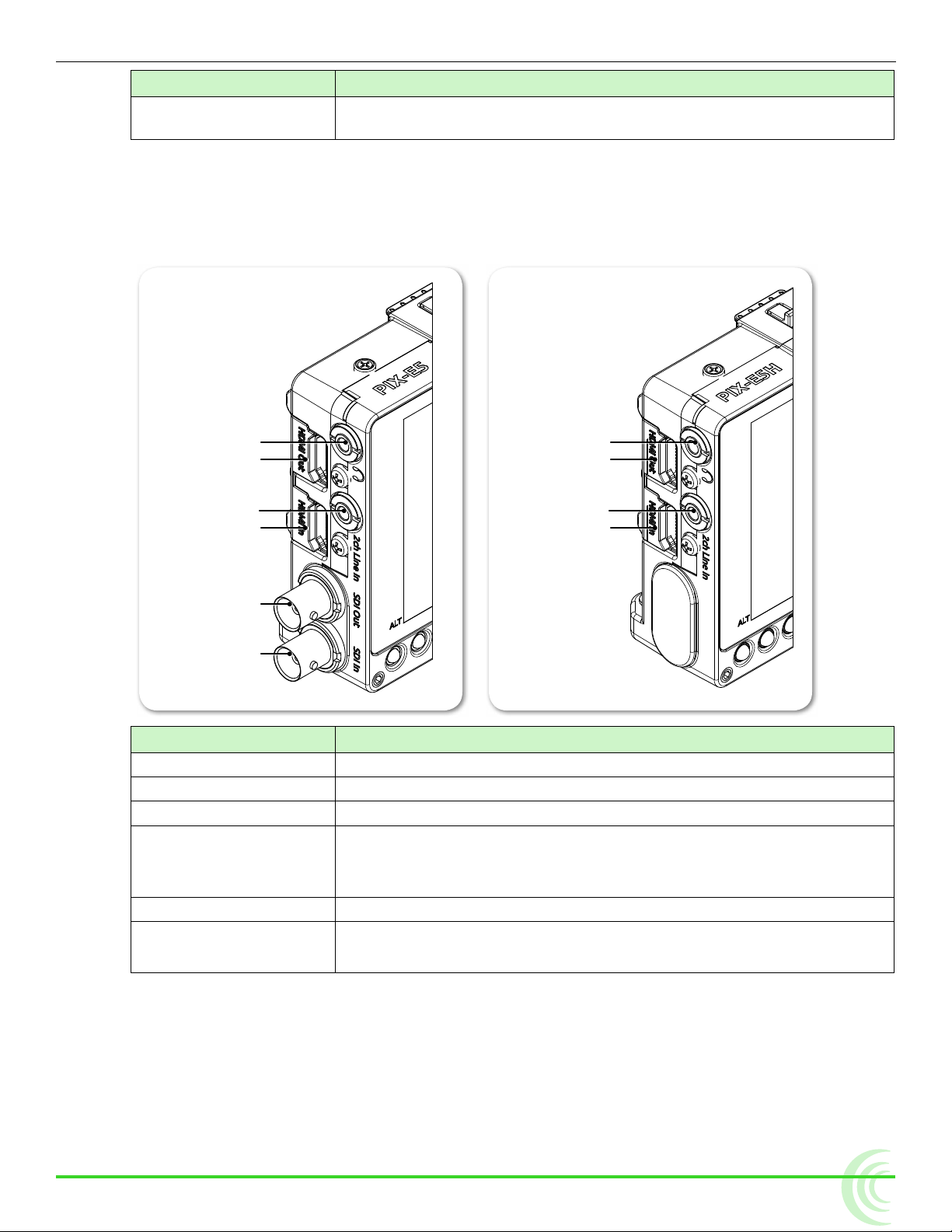
Feature Description
Headphone Output
HDMI Output
Audio Input
HDMI Input
Headphone Output
HDMI Output
Audio Line Input
HDMI Input
SDI Output
SDI Input
Soft Key Buttons Multi-functional buttons. Each soft key button’s function is displayed
Left Side Panel
The left side of the PIX-E5 provides various I/O ports for audio and video. The
PIX-E5H is an HDMI only unit, so it does not have SDI ports.
OVERVIEW OF THE CHASSIS
as a label on the LCD directly above the button.
Feature Description
Headphone Output 1/8-inch (3.5mm) unbalanced stereo headphone output.
HDMI Output Outputs HDMI video with up to two channels of embedded audio.
Audio Line Input 1/8-inch (3.5mm) unbalanced, line-level, 2-channel input.
HDMI Input Accepts HDMI (1.4a) signal with two channels of embedded audio.
i The monitor does not record or display content encoded with HDCP
copy protection.
SDI Output
SDI Input
*
*
* Applies to PIX-E5 only
Outputs up to 8 channels of embedded audio.
Accepts up to 8 channels of embedded audio.
9
Page 10
User Guide
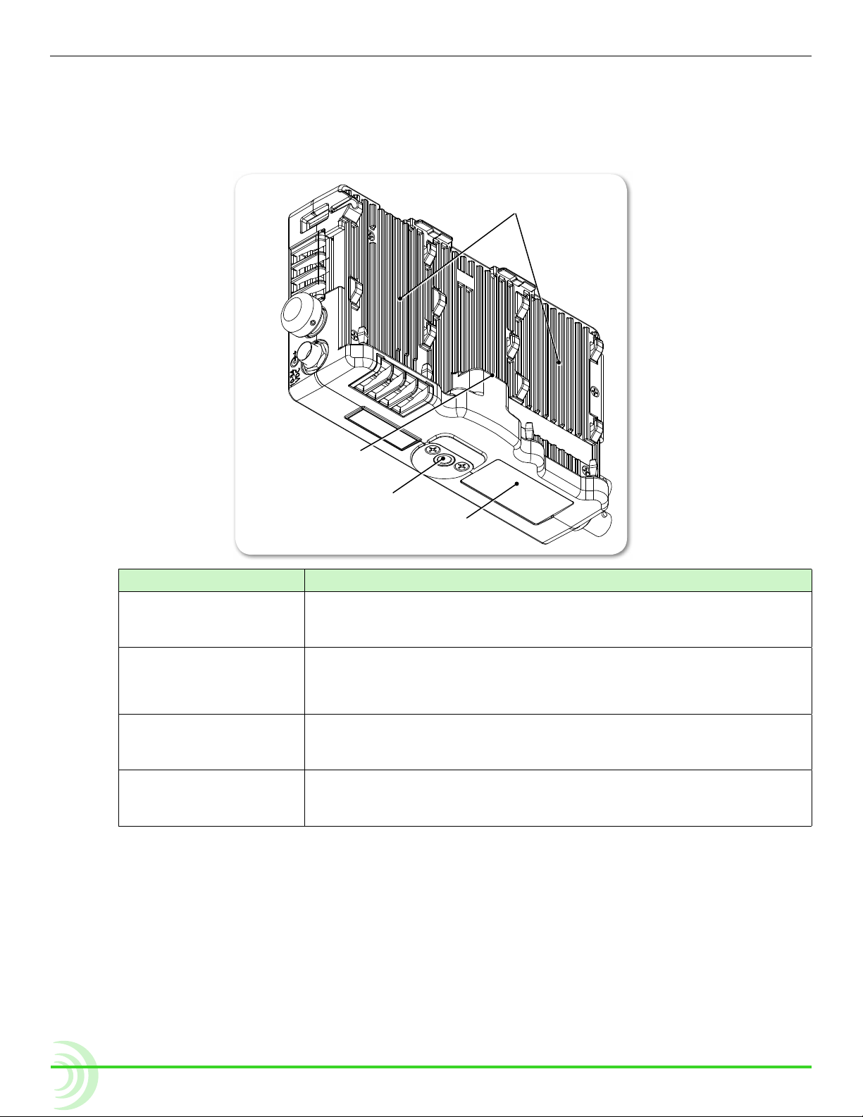
USB Connector
Battery Mounts
Mounting Point
Protective Cover
Back and Bottom Panels
The back panel features two battery mounts and a USB connector for mounting
a SpeedDrive. The bottom panels offers a 1/4-inch, 20-threaded mounting point
to secure the monitor to cameras and other devices.
Feature Description
Battery Mounts Located on the left and right side of the back panel are two mounts
for Sony® L-Series Lithium-ion batteries, or third-party batteries
compatible with the mount.
USB Connector Centered between the battery mounts on the back panel is the USB
connector for a SpeedDrive with installed mSATA drive.
i The USB connector cannot be used with any USB-based drive.
Mounting Point Centered on the top and bottom panels, a 1/4-inch, 20 threaded,
stainless-steel mounting point may be used to attach the monitor to
Protective Cover This removable cover is attached with adhesive to the monitor’s bot-
a camera or other production gear, such as the PIX-ARM.
tom panel and protects the connection used for integration with the
optional PIX-LR accessory.
⚠ Caution regarding battery usage: There is danger of explosion if the bat-
tery is incorrectly replaced. Replace only with the same or equivalent
type. Properly recycle batteries. Do not crush, disassemble, incinerate,
dispose in a re or expose batteries to high temperatures.
10
Page 11
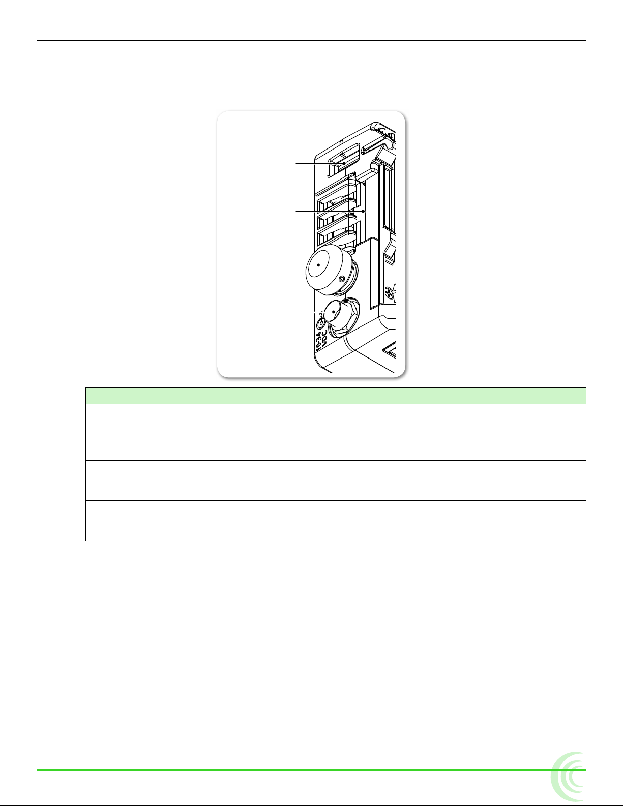
Right Side Panel
USB Keyboard Port
SD Card Slot
Control Knob
External Power Port
The right panel features a SD card slot, a Control knob, and ports for connecting external power or a peripheral USB keyboard.
OVERVIEW OF THE CHASSIS
Feature Description
USB Keyboard Port Use this port to connect a USB keyboard for entering metadata and
remote control.
SD Card Slot Accepts standard SD cards (SDSC, SDHC, and SDXC) for loading
rmware as well as saving and loading setup les.
Control Knob Use the Control knob to navigate menu settings (by turning it) and
selecting menu options (by pressing it in). It may also be used for
scrolling across screen while in zoom mode.
External Power Port Use to connect the PIX-E PSU. It accepts 10-34 VDC, threaded co-
axial connector (pin positive, sleeve negative) with a 5.5 mm outer
diameter and 2.1 mm inner diameter.
⚠ Caution regarding power supply: The PIX-E PSU must be connected to a
protective earthing connection to ensure safety. The power supply’s cord
acts as the disconnect device. The cord must be readily accessible and
remain readily operable.
11
Page 12

User Guide
12
Page 13

Menus and Navigation
Whether working on the set or in the
eld, time is precious, and monitoring
live recordings often requires quick
adjustments in fast-paced workows.
The PIX-E5 and PIX-E5H feature an
on-screen display (OSD)and menus
in an easy to navigate structure, with
many options readily accessible via the
touch screen or multi-functional soft key
buttons.
The Main menu is one press of a button
away with easy navigation via the
Control knob or touch screen.
Touch Screen and Tactile Controls
Topics in this section include:
Touch Screen and Tactile Controls
Accessing the MAIN MENU Screen
Toggling On-Screen Display Elements
Toggling Soft Key Button Functionality
Monitor Soft Keys
Record Soft Keys
Using Soft Key Menus
Configuring the On-Screen Display
USB Keyboard
Whether you want the quick efciency of a touch-screen interface or prefer the
tactile feedback of real buttons and want to keep the monitor’s screen free of
ngerprints, the PIX-E monitors offer a “best of both worlds” approach to user
controls.
All PIX-E LCDs are touch-screen enabled, but the monitors also feature tactile
buttons and a Control knob. Use the buttons to turn on or off monitor functions.
Elements of menus and dialogs may be selected or adjusted by touching the
screen or by using the Control knob, so you have the choice when it comes to
navigating through the user interface.
While directions throughout this guide describe how to use the Control knob for
navigation, touching the screen is often a quicker alternative.
Accessing the MAIN MENU Screen
The MAIN MENU screen displays an easy-to-navigate menu, organized with submenus, options, and parameters.
To access the MAIN MENU screen:
X Press the MENU button.
13
Page 14

User Guide
To navigate the Main menu with touch:
To navigate the Main menu with the Control knob:
1. Turn the Control knob to move the highlight up or down the menu.
2. Press in the Control knob to access a highlighted option.
Sub-menus and their options are covered in more detail in sections related to
those settings; however, the Main menu is provided with brief descriptions in
the following table:
Help Displays a quick reference list of shortcut key combinations and their
Recorder & Drives Displays the settings relevant to recording and drive formatting.
Metadata Displays the settings relevant to le-naming metadata stored in recorded
Video I/O Displays the settings that dene video input and output signals.
LUTs Displays the settings for conguring LUTs.
Audio Displays the settings that dene headphone warning bells and (optional)
Timecode Displays the settings that dene the timecode mode.
System Displays the system settings, such as date and time options.
Save/Load Settings Displays the options for saving customized settings to external storage
i If you press and hold the MENU button, the Monitor menu appears across the
lower portion of the screen.
X Touch a menu item to access it.
Main Menu Description
associated functions.
les.
PIX-LR setup.
media and loading those settings or reverting the device back to its factory settings.
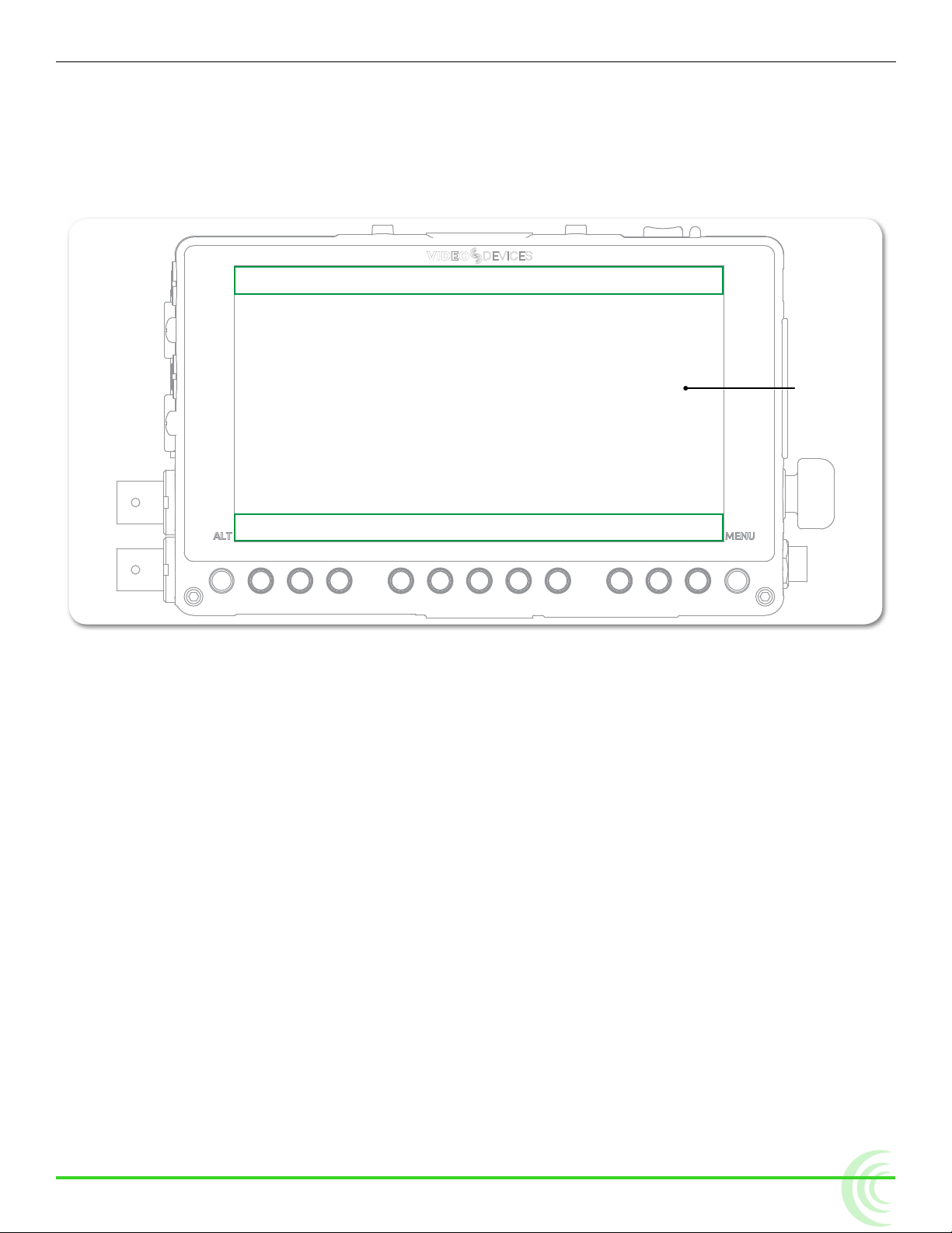
Toggling On-Screen Display Elements
The LCD displays a live or playback video image and the OSD, providing vital
information superimposed over the video.
The OSD is made up of two display elements, which may be viewed or hidden:
• Soft key labels — Located along the bottom of the screen, these identify
the current function of the soft key button directly below each label.
• Information bar — Located along the top of the screen, this bar is superimposed over the video image and shows transport status, the timecode,
ABS time, audio meters for channels 1 and 2, le name, a clock, and other
status information for a SpeedDrive and power sources. An alternative view
of the bar provides additional information, such as codec.
To show or hide soft key labels and/or the information bar:
X Press the Display soft key button. This button toggles through three display
options:
14
Page 15
MENUS AND NAVIGATION
◦ Show both information bar and soft key labels
◦ Show soft key labels; hide information bar
◦ Hide both information bar and soft key labels
i Holding down the Display soft key button for at least one second will show alterna-
tive data on the information bar, such as the codec being used, and a le’s resolution and rate.
Area Displaying Information Bar
LCD
Area Displaying Soft Key Labels
Toggling Soft Key Button Functionality
The primary functionality of soft key buttons is to toggle on or off monitoring
tools, such as: peaking, zebras, scopes, and more.
However, soft key buttons are multi-functional; their alternative functionality
includes accessing the File List and Audio screens, and acting as transport controls for recording and playback.
To toggle between monitor and record soft key functions:
X Press the ALT button. The displayed soft key labels above the buttons will
change, indicating their current function.
i The Display soft key label remains on-screen regardless of which functionality is
set for the other soft key buttons.
The following sections provide more details about what soft key labels appear
for the primary monitor versus alternative record functionalities.
15
Page 16

User Guide
Monitor Soft Keys
When soft key buttons are set for primary monitor functionality, the following
soft key labels appear and the buttons function as described:
LabeL Description
Display Hides or reveals OSD elements: soft key labels and/or the information
False Toggles on/off the display of the false colors exposure assist tool.
Zebra Toggles on/off the display of zebra stripes exposure assist tool.
4-Way Splits the screen into four quadrants, showing the video image in one
WFM Toggles on/off the full-screen display of the waveform monitoring tool.
Vector Toggles on/off the full-screen display of the vectorscope monitoring tool.
Hist Toggles on/off the full-screen display of the histogram monitoring tool.
LUT Toggles on/off the selected LUT.
Zoom2x / Zoom4x Toggles on/off the TapZoom functionality between different magnica-
bar.
quadrant and three scopes—waveform, vectorscope, and histogram—in
the other three.
tions of the video image: 2x (200%) or 4x (400%). This setting also
applies to zooming via use of the Control knob.
i If TapZoom is disabled, the label for this soft key button will be NoZoom.
Peak Toggles on/off the display of peaking lter focus assist tool.
Marker Toggles on/off the display of guide markers over the video image.
i Holding down most monitoring soft key buttons for more than a second will
open a menu related to that button’s functionality.
Record Soft Keys
When soft key buttons are set for alternate record functionality, the following
soft key labels appear and the buttons function as described:
LabeL Description
Display Hides or reveals OSD elements: soft key labels and/or the information bar.
Audio Displays the Audio screen. Track arm status, track name, input source, input
gain, and input delay can be viewed and adjusted for every track. Also displays metering for all tracks.
Files Accesses the Files screen, showing les recorded on the PIX-E5 as a list of
clips.
Stop Stops the recording or playback. When stopped, the label appears with a
yellow background and a yellow square icon appears on the information bar.
While stopped, pressing Stop reveals the next le name in the information
bar.
Play / Pause Starts playback. During playback, the label appears with a green background
and a green arrow icon appears on the information bar. The timecode, absolute time, and le name also appear green.
16
Pressing the button during playback will pause playback. While paused, the
Pause soft key label ashes, and the Pause icon ashes on the information
bar.
Page 17
LabeL Description
Rec Starts the recording. While recording, the label appears with a red back-
ground and a red circle icon appears on the information bar. The timecode,
absolute time, and le name also appear red.
Using Soft Key Menus
Commonly used settings are accessed via Soft Key menus. These menus differ
from the Main menu because they do not take up the entire screen. Instead,
they are superimposed over the lower portion of the screen, allowing any live
video to remain visible. Also, unlike the Main menu, the Soft Key menus may be
accessed during playback or while recording.
To access any Soft Key menu:
X Press and hold the button for 1 second. The button’s menu, if available, will
appear.
Specic buttons that feature Soft Key menus include:
MENUS AND NAVIGATION
button Description
MENU Called the Monitor menu, it displays settings for headphones and the
LCD, such as brightness, contrast, and so forth.
False The False menu displays options for setting the false color mode.
Zebra The Zebra menu displays settings and related options for zebras 1 and 2.
WFM The WFM menu displays settings and related options for the waveform
monitor.
Vector The Vector menu displays settings and related options for the vector-
scope.
Hist The Hist menu displays settings and related options for the histogram.
LUT The LUT menu displays four options to choose from; these options will
vary based on Main menu settings congured via MENU > LUTs.
Zoom The Zoom menu displays options for enabling or disabling the TapZoom
feature via the touch screen and zoom functionality via the Control knob.
Peak The Peak menu displays settings and related options for peaking.
Marker The Marker menu displays settings and related options for setting up
guide markers.
i Accessing a soft key menu for a monitor function will enable that monitor function
if it is not already enabled. There is no such menu for the 4-Way soft key button.
Also, there are no Soft Key menus available when soft key buttons are set to the
record functionality.
The layout of these menus varies. The simplest menu will consist of a single row
of options. The active option is highlighted in green.
17
Page 18
User Guide
Other such menus will feature settings in a nested tabular format. The tab of
the active setting is outlined in green.
You can use the touch screen or Control knob to navigate soft key menus.
To use a Soft Key menu:
1. Do either of the following:
X Use the Control knob by turning it to navigate tabbed settings and re-
lated options. Press in the Control knob to make a selection, and turn it
to adjust any values, such as sliders.
X Touch the screen to select a tabbed setting or related option. Touch and
swipe your ngertip along sliders to adjust any values.
2. When nished modifying settings, exit the menu by pressing the soft key
button again or touching elsewhere on the screen.
To reset the default of any Soft Key menu setting:
X With the menu’s setting displayed, press and hold the ALT button while
pressing in the Control knob.
Configuring the On-Screen Display
The look of the OSD may vary depending on the conguration of certain settings available in the Monitor menu. For instance, the brightness or contrast of
the display image might need adjusting. Or perhaps, the background for the
information bar and all soft key menus appears opaque instead of transparent
when superimposed over the video image.
18
To congure the Monitor settings:
1. Press and hold the MENU button for 1 second. The Monitor menu appears
superimposed over the lower portion of the screen.
2. Adjust the following settings as needed to achieve the look you want.
Page 19

setting Description options
See-Thru Use this setting to adjust the opacity of soft key menus and
Brightness Use this setting to adjust the brightness of the display image
Contrast Use this setting to adjust the contrast of the display image by
Chroma Use this setting to adjust the chroma level of the display im-
Backlight Use this setting to adjust the backlight level of the LCD by
i The Monitor menu also provides settings for adjusting headphone source and lev-
els. For more information, see Routing Audio Output.
USB Keyboard
MENUS AND NAVIGATION
0 to 100%
the information bar by increments of 25%. Set to 0% for fully
opaque and 100% for full transparency. This setting does not
affect the soft key labels, which are superimposed with a fully
transparent background. The default is 50%.
-20 to 20%
by increments of 1%. The default is 0%.
0 to 200%
increments of 1%. The default is 100%.
0 to 200%
age by increments of 1%. The default is 100%.
0 to 100%
increments of 5%. The default is 70%.
PIX-E monitors support the use of a standard USB keyboard connected to the
USB A connector on the right panel of the chassis. The keyboard may be used
to navigate menus, enter text, and perform various other functions.
context Key action
Shift ALT button
M, F12 MENU button
F1-F12
All
Live View Enter Enable TapZoom
Zoom mode
Audio screen &
File screen
Audio screen
with track selected
CTRL + R Record
Space Play/Pause
CTRL + S Stop
Esc Cancel / Go back
Enter Switch between horizontal and vertical positioning.
Up/Down arrow Reposition center point
Alt + Enter Exit TapZoom
Up arrow Move up one track or le
Down arrow Move down one track or le
Enter Select track or le
Esc Exit to main screen
Up arrow Move one eld to the right
Right arrow Move one eld to the right
Down arrow Move one eld to the left
Left arrow Move one eld to the left
Enter Select eld for editing
Soft Key buttons. F1 is the rst button to the right of the
ALT button, F2 is the next button to the Right, etc.
19
Page 20

User Guide
Audio screen
with Delay eld
selected
Audio screen
with Gain eld
selected
Audio screen
with Source eld
selected
On-screen
keyboard displayed
context Key action
Up arrow Increment delay by 10 ms
Down arrow Decrement delay by 10 ms
Enter
Esc
Up arrow Increment gain by 1 dB
Down arrow Decrement gain by 1 dB
Enter
Esc
Up arrow Select the next source up
Down arrow Select the next source down
Enter
Esc
Printable keys Are entered into the text eld
Enter
Esc Rejects edits closes the on-screen keyboard
Arrow keys Move the highlight on the on-screen keyboard
Backspace Deletes one character to the left
Del Deletes one character to the right
Accept edits and unselect both the edited eld and the
track
Accept edits and unselect both the edited eld and the
track
Accept edits and unselect both the edited eld and the
track
Accept edits and unselect both the edited eld and the
track
Accepts current selection and unselect both the edited
eld and track
Accepts current selection and unselect both the edited
eld and track
Selects the currently highlighted button on the on-screen
keyboard
20
Page 21
False Zebra 4-Way WFM Vector Hist Zoom Peak Marker
ALT Button
PIX-Assist Monitoring Suite
Topics in this section include:The PIX-E5 and PIX-E5H are powerful,
versatile eld monitors designed for use
with virtually any production camera.
Their LCD’s accurate color
representation and excellent off-axis
visibility, even on very sunny days,
provide a powerful visual aid for
achieving precise focusing, exposure,
color balance, and framing, enabling
the cinematographer to achieve their
creative vision.
The monitors feature the complete
PIX-Assist™ suite of monitoring
tools, offering the best graphical
representation of your video signal so
you can be sure what you see on the
monitor is exactly what you want in a
video recording.
Overview
Assist Tools
Using False Colors
Using Zebras
Using Zoom
Using Peaking
Scopes
Using the Waveform Monitor
Using the Vectorscope
Using the Histogram
Using 4-Way Monitoring
Using LUTs
Uploading Custom LUTs
Using Markers
Resetting Monitor Defaults
Overview
The PIX-Assist suite of monitoring tools consists of a collection of focus, exposure, and framing assist tools plus scopes. These tools affect the video signal
displayed on the monitor, and the scopes provide a live graphical analysis of
chrominance and luminance information in the video signal.
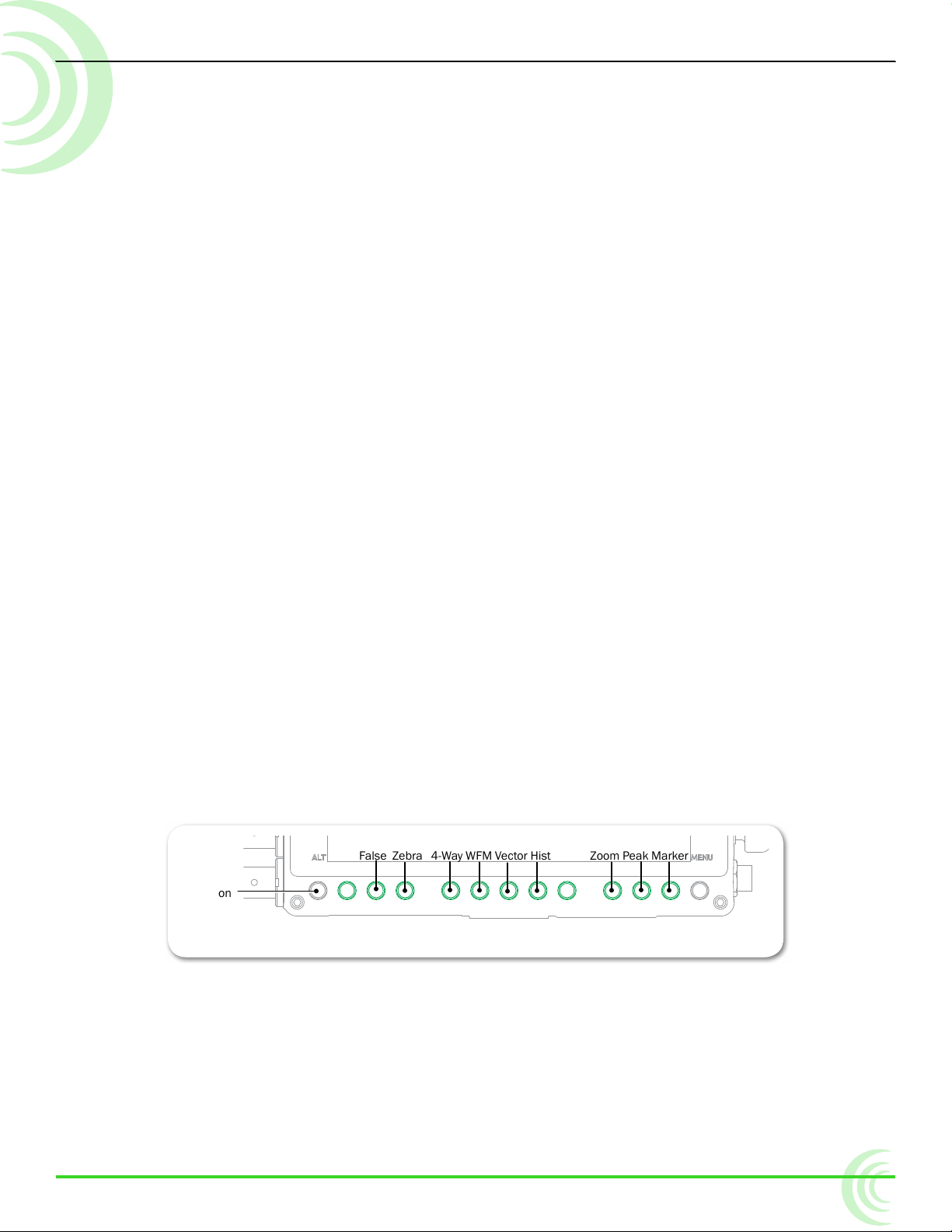
These monitoring features are controlled from soft key buttons, above which
are soft key labels indicating the button’s current functionality.
i If the monitor functionality of soft keys is not displayed, press the ALT button.
When a monitoring tool is activated, the label above the corresponding button
appears with a green background.
21
Page 22
User Guide
Assist Tools
The assist tools are those used to aid focusing and making adjustments for exposure. The tools include: false colors, zebras, zoom, and peaking.
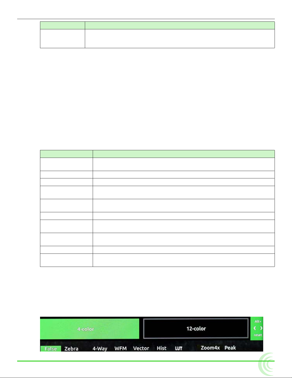
Using False Colors
False colors provides a quick way to achieve good exposure levels. They are
typically used to indicate over- and under-exposed regions in the video, as well
as aiding in setting exposure for skin tone and middle grey. The PIX-E monitors
offer two modes: 4-color and 12-color.
4-Color Applied
22
12-Color Applied
Video Image
Page 23

PIX-ASSIST MONITORING SUITE
The 4-color mode is ideal for quickly identifying over- and under-exposed regions. Under-exposed regions are highlighted blue and over-expoed regions as
yellow or red. All exposure levels in between are displayed as grey scale.
The 12-color mode is also used for identifying over- and under-exposed regions; however, it also provides a quick way to achieve correct exposure levels
for skin tone and middle grey. For example, correctly exposed Caucasian skin
tone typically shows as pink.
To enable or disable false color:
X Press the False soft key button.
To adjust false color settings:
1. Press and hold the False soft key button. The False menu appears.
2. Use the touch screen or Control knob to change settings.
options Description
4-color The 4-step mode divides the monitor signal
into 4 luminance ranges, assigning a color
to all but one range; this range is displayed
without chroma.
12-color The 12-step mode divides the monitor signal
into 12 luminance ranges, assigning a color to
each one.
Red and orange (95-108) ranges indicate
over-exposure.
Middle greys and skin tones typically fall in
the green, pink, and medium to light grey
(43-78) range.
Blue and white (0-12) ranges indicate under-exposure.
4-step
100-108 Red
95-99 Orange
3-98 N/A
0-2 Blue
12-step
100-108 Red
95-99 Orange
85-94 Yellow
79-84 Light Yellow
59-78 Light Grey
53-58 Pink
49-52 Medium Grey
43-48 Green
3. Press the False soft key button again to exit.
23-42 Dark Grey
13-22 Light Blue
3-12 Blue
0-2 White
23
Page 24

User Guide
Zebra 1
85 %
Zebra 2
70 % (+/-5%)
Using Zebras
Zebras provides an alternative method for identifying exposure levels in an
image. They appear as black and white diagonal stripes that are superimposed
over regions of an image that exceed a threshold or specic value range of luminance. PIX-E monitors have three modes: Zebra 1, Zebra 2, and Zebra 1+2.
The following image shows both zebra 1+2 overlays with default settings.
Zebra 1 stripes are forward leaning and are typically set to identify a particular
brightness range (value +/-5%), such as skin tones or mid tones.
Zebra 2 stripes are backward leaning and are typically set to identify when a
specic brightness level is exceeded. They are often set to identify over-exposed image or when textures and details in whites start to get lost.
Zebra 1+2 simultaneously superimposes both on the video image.
To enable or disable zebras:
X Press the Zebra soft key button.
The button is a toggle, so pressing it a second time turns off the zebra overlay.
When enabled, the Zebra soft key label appears with a green background.
To adjust zebra settings:
1. Press and hold the Zebra soft key button. The Zebra menu appears.
24
Page 25

PIX-ASSIST MONITORING SUITE
2. Use the touch screen or Control knob to change settings.
setting Description options
Select Zebra Display Sets which zebra is displayed when zebras are
enabled.
Zebra 1 Level The luminance range where Zebra 1 will be
displayed. The top of the range is 5% above
this setting, and the bottom of the range is 5%
below.
Zebra 2 Threshold Zebra 2 will be displayed for signal above this
threshold.
• Zebra 1
• Zebra 2
• Zebras 1 + 2
• 0% - 105%
• 0% - 108%
3. Press the Zebra soft key button to exit.
Using Zoom
For fast and precise focusing on both static and moving subjects, PIX-E monitors provide 2x and 4x magnication and the ability to rapidly adjust the center
point of focus. Zoom can be controlled using the touch screen or the Control
knob.
TapZoom™ is the fastest way to zoom in and out on a subject. Utilizing the
PIX-E monitors’ touch screen, TapZoom lets focus pullers and camera operators
check focus by simply tapping a point on the video image to zoom in on a target. A second tap zooms back out.
For those who prefer to not use the touch screen, zoom can also be activated
using the Control knob.
To zoom in on a point of interest:
X Tap that point in the image.
X Press in the Control knob.
To zoom out to full image:
X Tap center of screen.
X Press ALT+Control knob.
25
Page 26

User Guide
Locator Graphic
POS Arrows
Zoom
Soft Key
Label
see DeMo ViDeo
Magnication is controlled by a Zoom soft key button, and the soft key label
displays the current setting related to the Zoom feature.
soFt Key LabeL Description
Zoom2x When set to 2x, activating zoom will zoom with 200% magnication.
Zoom4x When set to 4x, activating zoom will zoom with 400% magnication.
NoZoom Indicates when zoom functionality is disabled.
When zoomed in, the monitor centers the screen on the tapped target, displays
the word ZOOMED in red, and provides a rectangular locator graphic to pinpoint
zoomed area within the full image. That location is known as the center point.
Below the locater graphic is POS, or repositioning options, with arrows indicating the direction in which you can move that center point.
To reposition the center point:
X Swipe your ngertip across screen to move the zoomed-in image around on
the screen. The center point is repositioned accordingly.
X Turn the Control knob to reposition the center point. Press the knob in to
switch between horizontal or vertical positioning.
26
Targets in Motion
Repositioning the center point works well for stationary subjects, but if a subject moves, a quick tap in certain zones can help recenter the zoomed view,
keeping your shot on target. The screen is split into nine zones.
Page 27

PIX-ASSIST MONITORING SUITE
While zoomed in, you may tap toward the edges of the screen to follow a moving subject around within a shot, or tap the center of the screen to return to a
non-magnied view of the overall shot.
Enabling or Disabling Zoom
Zoom is a feature that may be disabled.
To enable or disable Zoom:
1. Press and hold the Zoom soft key button. The Zoom menu appears superimposed over the lower portion of the screen.
2. Do one of the following:
X Select Zoom Enabled to turn on zoom functionality.
X Select Zoom Disabled to turn off zoom functionality.
When disabled, the Zoom soft key button no longer toggles between magnication settings, and its soft key label displays NoZoom.
Using Peaking
Peaking is a focus-assist tool that makes it easy to discern an object in focus by
visually highlighting sharp edges. It can also be used in conjunction with zoom
to rapidly achieve ultra-precise focus.
PIX-E provides a range of options to help make the sharp focused edges stand
out regardless of the color and content of the video image. These options include user-customizable peaking sensitivity, color, throb, background contrast
and background color.
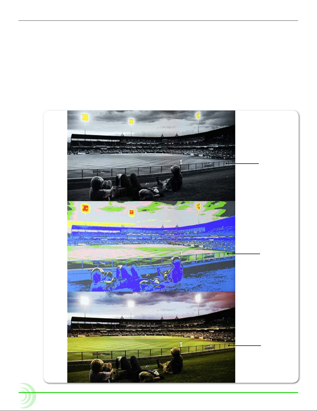
The following comparison demonstrates the effect of peaking (shown in red) on
an monochrome image with a shallow depth-of-eld and a short focal length
27
Page 28

User Guide
(top) and the same image with a longer focal length (bottom).
To turn on peaking:
X Press the Peak soft key button.
To adjust various settings related to peaking:
1. Press and hold the Peak soft key button. The Peak menu appears.
2. Use the touch screen or Control knob to change settings.
setting Description options
Peaking Sensitivity Use to dene the sensitivity level for peaking.
The lower the value, the less sensitive the peaking lter will be to non-sharp edges. The default
is 50%
Peaking Color Choose the color to be used to highlight the
sharp edges in a video image. To help the edges
stand out, use a color that is not dominant in the
image. The default color is Red.
• 5% - 100%
• Red
• Green
• Blue
• White
• Yellow
28
Page 29

Scopes
PIX-ASSIST MONITORING SUITE
setting Description options
Peaking Throb Set the peaking color to ash by turning this set-
ting on and setting the speed. The default is Off.
Background Contrast Sets the contrast of the background image.
Lower the value to help the highlights be more
visible. The default is 100%.
Background Color Sets the background image as Color or Mono-
chrome. The default is Color.
• Off
• Slow
• Fast
• 0% - 100%
• Color
• Monochrome
3. Press the Peak soft key button again to exit.
Scopes provide cinematographers and videographers the ability to accurately
set exposure and color balance as well as make creative choices about the look
of a scene.
PIX-E monitors offers three types of scope: the waveform monitor, the vectorscope, and the histogram. Each scope plots color and/or brightness information
onto a graph which can be viewed full screen over an opaque background or
superimposed over the video image. There is also a 4-way monitoring mode for
viewing multiple scopes with the video image.
Using the Waveform Monitor
The waveform monitor (WFM) is a tool for checking and aiding in setting exposure levels both for brightness and color. Its precision graticule provides more
detail and accuracy than either false colors or zebras. Use WFM to check exposure for skin tone, consistent background lighting, background separation on
green screen shots, and for avoiding over-saturated colors.
The WFM’s vertical axis ranges from -10% to 110% and represents brightness
(luma) or color (chrominance) levels for each pixel in an image. 100% corresponds to nominal white and 0% to black. The -10% and 110% limits allow for
monitoring of super blacks and whites.
The WFM’s horizontal axis corresponds to the position of image content going
from left to right.
The monitor provides four WFM modes: Luma (white), Luma (green), RGB
Overlay, and RGB Parade.
29
Page 30

User Guide
The following table provides illustrative examples for each of these modes:
Luma (white) Displays luminance only trace in white or green.
Luma (green)
RGB Overlay Displays red, green, and blue (RGB channels) color in-
RGB Parade
type exaMpLe Description
Use to:
• accurately set exposure for skin tone where typical
range is 45% (darker tones) to 60% (lighter tones).
• help to set consistent background lighting. For example, a uniform background lighting will appear as
an approximately at horizontal trace from left to
right.
formation overlaid one over another or horizontally, one
after another: red, green, and then blue.
Use to:
• check if RGB levels are clipping. This information
may not show up in Luma mode.
• check white balance. RGB levels should be the
same.
• check adequate separation between green, red and
blue for green screen shots.
To view/hide the waveform monitor:
X Press the WFM soft key button.
The button is a toggle, so pressing it a second time turns off waveform.
To adjust percentage of intensity (trace brightness) of the WFM:
X While viewing the WFM, rotate the Control knob. The level is
displayed on screen next to the Control knob.
To adjust waveform monitor settings:
1. Press and hold the WFM soft key button. The WFM menu appears.
2. Use the touch screen or Control knob to change settings.
setting Description options
Waveform Type The type of waveform monitor to display. • Luma (white)
• Luma (green)
• RGB Overlay
• RGB Parade
Background Video
Contrast
The contrast level of the background video
when monitor is displayed. The default is 35%.
• 0% - 100%
30
i For a black background, adjust to 0%.
Page 31

PIX-ASSIST MONITORING SUITE
Using the Vectorscope
The vectorscope is a circular graphical tool for monitoring color (chrominance)
information. It can be used for helping eliminate unwanted color casts (offsets),
checking white and black balance, ensuring color saturation falls within a legal
broadcast color gamut, and for making creative choices about overall look.
Color saturation is determined by the distance from the center of scope - the
more saturated (vivid) a color, the further its trace reach is from the center. A
greyscale image should appear as a dot in the center of the scope.
Color hue is determined by the direction or angle of the trace. Small boxes represent target values for fully saturated REC 709 primary and secondary color
bars (red, green, blue, yellow, magenta, cyan). The line between the red and
yellow target boxes that runs from center to outer circumference indicates skin
tone.
i Tip: To quickly check for color offset, view the vectorscope whilst performing a
white and/or black balance. The trace should appear as a fuzzy dot (for white) or
smaller dot (for black) in the center of the scope.
To view/hide the vectorscope:
X Press the Vector soft key button.
To adjust percentage of intensity (trace brightness) of the vectorscope:
X Rotate the Control knob while viewing the vectorscope. The level is dis-
played on screen next to the Control knob.
To adjust vectorscope settings:
1. Press and hold the Vector soft key button. The Vectorscope menu appears.
31
Page 32

User Guide
2. Use the touch screen or Control knob to change settings.
setting Description options
Vectorscope
Magnication
Background Video
Contrast
Using the Histogram
The histogram is a tool for checking overall brightness (luma) or color level
(chrominance) within an image. It displays how many pixels there are at each
brightness or color level. The horizontal axis represents luma level with black
being on the left and white on the right. The vertical axis represents the relative number of pixels at that luma level. Use it to quickly determine that you
are capturing the full dynamic range - most pixels should be distributed broadly
around the center of the horizontal axis, not hard left (under-exposed) or hard
right (over exposed).
Set the magnication multiplier of the vectorscope.
The contrast level of the background video
when waveform monitor is displayed.
i For a black background, adjust to 0%.
• 1.000x - 5.000x
• 0% - 100%
The horizontal range of the histogram is -10% to 110%, matching the vertical range of the WFM, where 0% is legal black and 100% is legal white. The
-10% and 110% limits allow for monitoring full range ‘super blacks’ and ‘super
whites’.
The monitor provides 4 histogram modes: Luma (white), Luma (green), RGB
Overlay, and RGB Parade. The following table provides illustrative examples for
each of these modes:
type exaMpLe Description
Luma (white) Displays luma only trace in white.
Luma (green) Displays luma only trace in green, offering a look
reminiscent of green-screen oscilloscopes.
RGB Overlay Displays RGB pixel distribution overlaid, one over
another, as a horizontal trace.
32
RGB Parade Displays RGB pixel distribution overlaid vertically one
after another: red rst, green second, and then blue.
Page 33

To view/hide the histogram:
Vectorscope
HistogramVideo
Waveform
X Press the Hist soft key button.
To adjust histogram settings:
1. Press and hold the Hist soft key button. The Vectorscope menu appears.
2. Use the touch screen or Control knob to change settings.
setting Description options
Histogram Type Sets the type of histogram to display. • Luma (white)
Background Video
Contrast
Using 4-Way Monitoring
PIX-ASSIST MONITORING SUITE
The contrast level of the background video
when waveform monitor is displayed.
i For a black background, adjust to 0%.
• Luma (green)
• RGB Overlay
• RGB Parade
• 0% - 100%
4-Way monitor mode splits the screen into 4 quadrants, simultaneously displaying the video signal, histogram, waveform, and vectorscope. This provides a
great overview of exposure and color attributes of the incoming video.
The following image shows an example of the display while in 4-way monitoring
mode.
When in 4-way monitoring, a tap on any one of the four quadrants will enlarge
the view displayed in that quadrant to full screen.
see DeMo ViDeo
To begin 4-way monitoring:
X Press the 4-Way soft key button.
X Tap the screen while viewing the full-screen histogram, vectorscope, or
waveform monitor.
33
Page 34

User Guide
The overlay monitoring assist tools are still available when 4-way is displayed.
For instance, you can turn on 4-way monitoring and view the video in the top
left quadrant with peaking, false color, or zebras overlaid on the image.
To exit 4-way monitoring:
X Press the 4-Way soft key button again.
X Tap any one of the four quadrants to expand that view full screen.
i While a tap will expand one of the three scopes full screen, a second tap will tog-
gle back to 4-way monitoring. That is not the case with the video quadrant; a tap
there will exit 4-way and restore full screen viewing of the video signal. A second
tap afterward will, if TapZoom is enabled, zoom in on the image.
Using LUTs
To aid onset viewing, most camera manufacturers provide monitoring LUTs
(lookup tables) to convert the cameras’ LOG output into easily viewed imagery
that more accurately represents the nal image.
The PIX-E monitors come equipped with several standard LUTs, but custom
LUTs may also be used via SD card or SpeedDrive.
When a LUT is active, it is applied to the LCD and video outputs.
To activate or deactivate a LUT:
X Press the LUT soft key button. The LUT soft key label appears green when a
LUT is activated.
To compare LUTs and view the name of the currently selected LUT:
1. Press and hold the LUT soft key button.
34
Page 35

PIX-ASSIST MONITORING SUITE
The LUT menu appears superimposed over the image, along the bottom
of the screen, with four LUT options. The currently applied LUT appears
highlighted in green.
i The four options in the menu will vary depending on how LUTs are congured.
2. Tap each option to view the video image based on the chosen LUT.
To congure the LUT menu options:
1. Press MENU.
2. Select LUTs. The LUTS screen appears.
3. Dene each of the four options: LUT1, LUT2, LUT3, LUT4 by selecting from
the settings listed. The following table describes the standard settings
available.
setting Description
Off Select if you want one of the four options available
via the LUT soft key button menu to be Off. This
is useful as a quick LUT bypass when comparing
different looks.
Canon Log REC709 Canon logs are provided for use with Canon® camer-
Canon Log2 REC709
S-Log2 REC709 S-logs are provided for use with Sony® cameras.
S-Log3 LC709
S-Log LC709A
V-Log REC709 The V-log is provided for use with Panasonic®
i The list could vary depending on if any custom LUTs are in the LUTs folder on the
attached SD card or SpeedDrive. Custom LUTs are appended to the end of the
list.
as.
cameras.
35
Page 36

User Guide
Uploading Custom LUTs
Custom lookup tables in .cube le format may be used with PIX-E monitors
from either a SpeedDrive or SD card.
To upload a custom LUT:
1. Ensure the SpeedDrive or SD card has been formatted by the PIX-E monitor. For more information on formatting drives with the PIX-E montior, see
Formatting Storage Drives.
When the drive or card is formatted by the PIX-E monitor, a LUTs folder is
created. All custom LUTs must be placed in this folder for the monitor to
properly identify and retrieve the .cube les.
i Do not use a period in the LUT le name.
2. Insert the SpeedDrive or SD card into a computer.
3. Copy the custom LUT (.cube le) to the LUTs folder on the SpeedDrive or
SD card.
4. Mount the SpeedDrive or insert the SD card into PIX-E monitor.
All custom LUTs will be appended to the end of the list available for selection via MENU > LUTs.
36
Page 37

Using Markers
Guide markers are used to help frame and compose shots and dene safe areas. The PIX-E monitors feature three different types of markers: frame , grid,
and a center indicator.
The center indicator may be a dot or a cross, or both, and is used to mark the
center point of a shot.
PIX-ASSIST MONITORING SUITE
Frame
Mask
Center Indicator
Soft Key Label
A frame marker is a thinly lined rectangle used to “frame” the shot. The frame
may be customized to match the aspect ratio of the video, such as 16:9 for
high-denition television. The area within the rectangular frame is safely “inside” the shot; the area outside the rectangle is the mask, which is considered
“outside” the shot. There are two frame markers available on the monitor, which
may be congured separately.
A grid marker divides up the frame into thirds or quarters, forming a grid pattern.
To show or hide markers:
X Press the Marker soft key button, which toggles the display of markers on
or off. The Marker soft key label appears with a green background when
markers are displayed.
i Turning off all individual markers via their respective settings disables the Marker
soft key button.
With Markers enabled, all markers that are turned on will be visible in the video
monitor. Each type of marker is enabled via its respective settings section.
37
Page 38

User Guide
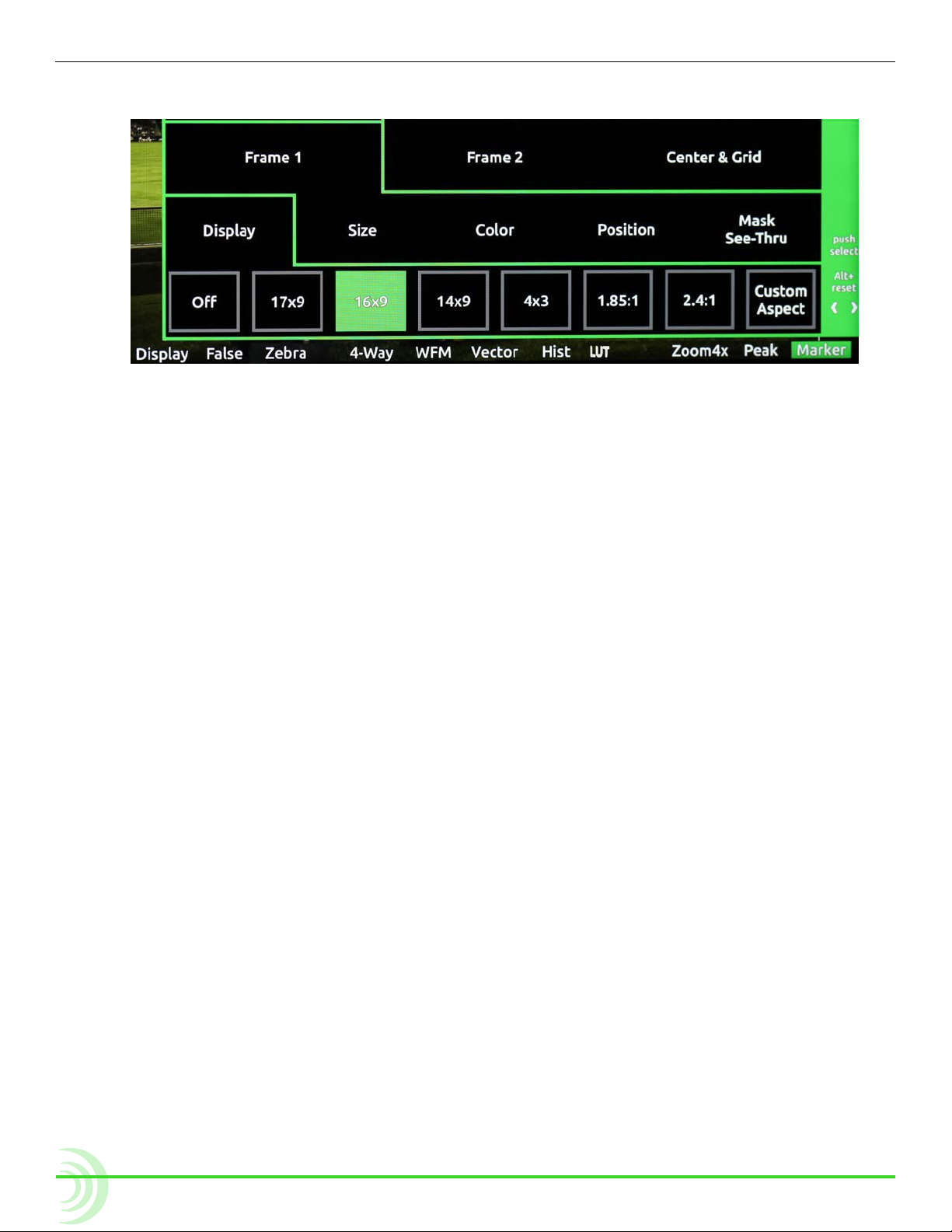
To adjust marker settings:
1. Press and hold the Marker soft key button. The Marker menu appears
2. Do one of the following:
superimposed over the lower portion of the screen.
X Use the touch screen to view and change settings.
X Turn and press the Control knob to select and change settings.
Markers have three main settings—Frame 1, Frame 2, and Center & Grid,
each with its own sub-settings and options.
Frame 1 and Frame 2 have identical sub-settings—Display, Size, Color, Position, and Mask See-Thru—as described in the following table:
setting sub-setting Description options
Frame 1 /
Frame 2
Display Use this setting to adjust the marker’s
aspect ratio.
Size Use this setting to adjust the percentage
of the screen making up the inside area of
the frame. For instance, if set to 90%, then
the rectangular frame will make up 90% of
the screen, while 10% will be masked out
around the outer perimeter.
Color Use this setting to adjust the color of the
rectangular line forming the frame.
• Off
• 17x9
• 16x9
• 14x9
• 4x3
• 1.85:1
• 2.4:1
• Custom
Aspect
• 1% - 100%
• White
• Light Gray
• Gray
• Dark Gray
• Black
• Red
• Green
• Blue
38
Page 39

PIX-ASSIST MONITORING SUITE
setting sub-setting Description options
Center &
Grid
Position Use this setting to position the frame on
the screen.
Mask See-Thru Use this setting to adjust the opacity of
the masked area outside the rectangular
frame.
Set to 0% for fully opaque and 100% for
full transparency.
Center Use this setting to enable the display of a
cross and/or dot, superimposed at the center point of the video image.
Center Color Use this setting to adjust the color of the
cross and/or dot, if used.
Grid Use this setting to enable the display of a
grid marker pattern of lines, superimposed
over the video image. If set to 1/3, the
screen is divided into a grid of 9 squares. If
set to 1/4, the screen is divided into a grid
of 12 squares.
• Centered
• To p
• Custom
Position
• 0% - 100%
• Off
• Cross
• Dot
• Cross+Dot
• White
• Light Gray
• Gray
• Dark Gray
• Black
• Red
• Green
• Blue
• Off
• 1/3
• 1/4
i The grid, if enabled, will only appear
within Frame 1. Grid markers do not apply to Frame 2.
Grid Color Use this setting to adjust the color of the
grid lines if that marker pattern is used.
• White
• Light Gray
• Gray
• Dark Gray
• Black
• Red
• Green
• Blue
39
Page 40

User Guide
Resetting Monitor Defaults
Restoring factory defaults via the Main menu resets all settings for all features
on the monitor, but settings can be reset on an individual basis.
To restore a setting to factory default:
1. Open the soft key menu and navigate to view the setting you want to reset.
2. Press and hold the ALT button, while pushing in the Control knob.
This only resets one setting at a time, and not all settings available in the
menu.
40
Page 41

Storage
SpeedDrive and a high-capacity SD
memory card.
Both media can be easily removed from
the monitor and inserted into standard
USB or SD ports on computers, making
the transfer of les easy and efcient.
PIX-E recorders format and write to an
exFAT le system. The exFAT le system
is readable and writable by all current
major operating systems.
i A list of storage devices approved for
use with PIX-E monitors is available at:
www.videodevices.com/approved
Topics in this section include:The PIX-E monitors can accept a
SpeedDrive
SD Memory Card
Metadata and File Name Format
File Name Formats
Formatting Storage Drives
Working with Files
Deleting Recorded Files
Transferring Files to a Computer
SpeedDrive
The PIX-E5 writes Apple ProRes video les to SpeedDrive™ media. The SpeedDrive is a portable enclosure for a Mini-SATA (mSATA) drive with a USB 3.0
interface. The SpeedDrive ships with a 240GB mSATA drive installed or as an
enclosure only.
ProRes 4k video recording produces an extremely high data rate which produces
quite a bit of heat no matter what recording medium. The SpeedDrive enclosure
is expressly designed to wick the heat away from the SSD via its thermally conductive gap-pad and heat sink. Though the SpeedDrive can be very warm to the
touch, this is by design to keep the SSD as cool as possible.
To attach a SpeedDrive to the monitor:
1. Place the SpeedDrive so that the USB plug lines up to the
USB connector on the back of the monitor.
2. Depress the spring-loaded retainer clip, located at the
back edge of the monitor’s top panel. Only one of two
clips is used to hold the SpeedDrive, and it is labeled
SSD.
3. Slide the SpeedDrive into the USB connector.
see DeMo ViDeo
41
Page 42

User Guide
SD Memory
Card Slot
The retainer clip will spring into the notch on the SpeedDrive with a click,
indicating the SpeedDrive is securely attached to the monitor.
The storage volume will then be available on the PIX-E interface and appear
as Drive 1 (D1) on the information bar.
i A SpeedDrive may also be used to upload custom LUTs. Before using a Speed-
Drive, it must be formatted by the monitor. For more information, see Formatting
Storage Drives.
To remove a SpeedDrive:
1. Depress the left retainer clip, labeled SSD, holding the SpeedDrive in place.
2. Carefully slide the SpeedDrive out of the USB connector.
SD Memory Card
The monitor can save and recall its settings on a Secure Digital (SD) ash
memory card, which can also be used to upload LUTs.
It accepts these cards:
• Standard-capacity
(SDSC: 1MB - 2 or 4GB)
• High-capacity
(SDHC: 2GB - 32GB)
• Extended-capacity
(SDXC: 32GB - 2TB)
To install the SD card:
X Slide the SD card into the SD
Memory Card slot on the right panel of the monitor.
i Before saving setup les or custom LUTs to an SD card, it must be formatted by
the monitor. For more information, see Formatting Storage Drives.
Metadata and File Name Format
The monitor lets the user enter scene, take, camera ID, reel, and clip information. Files generated by the monitor are named according to this information,
making it easy for post production to identify recordings. These metadata options are located in the Metadata section of the Main menu.
SD
42
To view or modify Metadata settings:
1. Press the MENU button.
2. Select Metadata.
3. Use the touch screen or Control knob to select and modify the settings as
needed.
Page 43

setting Description options
Scene/Shot Accepts alphanumeric values. Use this metadata
eld to indicate a descriptive name for the current scene or shot. A change to the Scene/Shot
value will automatically reset the Take value to
1.
Tak e Sets numeric values only. Use this metadata eld
to indicate what take number the clip is, relative
to the scene. This eld can be set manually and
will increment each time a new le is recorded.
A change to the Scene/Shot value will reset Take
to 1.
CamID Sets a single alpha character (A - Z). Use this
metadata eld to indicate which physical camera,
in a multi-cam production, shot the content for
the take.
Reel Accepts alphanumeric values. Use this metadata
eld to indicate what reel the recording is part
of; a reel is a container for all assets generated during a recording session or day’s work. A
change to the Reel value will reset the Clip value
to 1.
Clip Accepts numeric values (1-999). Use this meta-
data eld to indicate what clip number the
recording is. This eld can be set manually and
will increment each time a new le is recorded. A
change to the Reel value will reset Clip to 1.
File Name Format Use this eld to set the naming format for les.
For more information, see “File Name Formats”
on page 43.
• Text entry
• 1-999
• A-Z
• Text entry
• 1-999
• Drive-Reel-Clip
• Reel-Clip
• CamID-Reel-Clip
• Reel-Scene-Take
• Scene-Take
STORAGE
File Name Formats
Files are named according to the File Name Format setting, accessed via Main
menu > Metadata. Format options for le names includes various combinations
of the metadata elds: CamID, Reel, Scene/Shot, Take, and Clip. These descriptive le name formats make it easy to identify recordings when imported into a
nonlinear editor.
43
Page 44

User Guide
Formatting Storage Drives
Before using SD and SpeedDrive media, they must be formatted with the
monitor.
i PIX-E monitors over-provision drive space by 10%.
To erase/re-format a drive:
1. Connect the drive to be formatted.
2. Press the MENU button to view the Main menu.
3. Turn and press the Control knob to select Recorder & Drives > Erase/Reformat Drive.
4. Turn and press the Control knob to select the sub-option associated with
the drive for formatting. Sub-options include: SpeedDrive, SD Card, or Both
drives.
5. A cautionary conrmation dialog will appear on screen asking if you want to
continue. Select Yes to continue. An on-screen keyboard appears.
6. Either accept the default volume name (PIX-E) or use the keyboard to enter
a new volume name.
7. Select OK to continue.
Working with Files
Files recorded on the monitor are compiled in the SpeedDrive File List, as a list
of clips arranged chronologically. The total size (in GB), created date / time, and
duration of each le is provided in the list.
44
Page 45

To view recorded video les:
1. Press the Files soft key button.
2. Turn the Control knob to navigate through the list.
3. Do any of the following:
X With a le highlighted, press Play to begin playback of the video.
X With a le highlighted, press the Control knob to view its details.
Details provided for each le (if available) are:
• Start Timecode • Frame rate & Resolution • Timecode FPS
• Duration • Codec • User bits
• Created • Audio Format • File size
Deleting Recorded Files
Deleted les are permanently removed from the drive and cannot be restored.
To delete a le:
STORAGE
1. Press the Files soft key button.
2. Turn the Control knob to navigate the list and press it in to select the le
you want to delete.
3. Select Delete. An important message appears prompting for conrmation.
4. Select OK to permanently delete the le.
Choosing Cancel exits without le deletion.
Transferring Files to a Computer
QuickTime les on the SpeedDrive may be copied to a computer for post-production editing. These les are compatible with Avid, FinalCut Pro, and Adobe
Premier Pro.
To transfer les:
1. Remove the SpeedDrive from the monitor.
2. Insert the SpeedDrive into a USB 3.0 compatible port on the computer.
3. Copy the les to the computer.
Sound Devices, LLC recommends rst copying les from the storage device to
the computer and then editing the copied les.
⚠ Do not copy video les from a computer (or any other host device) to
a drive that is intended to be used by the monitor. If this occurs, it is
advisable to re-format the drive with the monitor before making new
recordings.
45
Page 46

User Guide
46
Page 47

Recording and Playback
Topics in this section include:Although the PIX-E5 and PIX-E5H are
powerful camera-mount monitors, they
also have fully integrated recording
capabilities.
Both can record Apple ProRes les and
playback the recorded QuickTime les
from a SpeedDrive.
i Sound Devices recommends the
camera’s output be set to required
frame resolution and rate before
connecting the camera to the PIX-E
monitor.
Record and Playback Icons
Recording
Playing Back Recorded Files
Choosing a Video Input Source
Setting up a Record Trigger
Selecting a Video Codec
Setting PsF Options
FileSafe
Viewing the File List
Record and Playback Icons
The information bar at the top of the screen displays various information related
to the recording process, such as timecode and le names, but it also displays
transport status icons. The following table provides a quick reference to these
icons.
icon status Description
Record The red circle icon is displayed when recording is in progress.
Stop The yellow square icon is displayed when recording or playback is stopped.
Play The green arrow icon is displayed when playback is in progress.
Pause The green pipes icon ashes when playback is paused.
Recording
The PIX-E5 accepts SDI or HDMI signals, and the PIX-E5H accepts only an HDMI
signal. Both record Apple ProRes QuickTime les to an attached and formatted
SpeedDrive. The SpeedDrive must be formatted by the PIX-E monitor. For formatting instructions, see Formatting Storage Drives.
47
Page 48

User Guide
To start recording:
To stop recording:
X Press the Rec soft key button.
i If the transport controls (REC, STOP, PLAY) are not visible, press ALT to switch the
soft key buttons to their alternative transport functionality.
While recording, the OSD will change to indicate recording activity:
• Absolute Time display is red • Red circle icon appears on information bar
• Timecode display is red • Rec soft key label’s background is red
• Filename display is red • Drive status display is amber
Also, the LED on the SpeedDrive illuminates amber when the drive is accessed by the monitor.
⚠ Do not remove the SpeedDrive while its LED is illuminated.
X Press the Stop soft key button.
When stopped, the Stop soft key label’s background is yellow, and a yellow
square icon appears in the top left of the information bar.
Choosing a Video Input Source
Selecting which input to use as the video input source is an option on the
PIX-E5, since the PIX-E5 features both HDMI and SDI inputs.
To select SDI or HDMI input:
1. Press the MENU button.
2. Select Video I/O > Video Input.
3. Select SDI or HDMI.
i A best practice tip is to disconnect and reconnect the video input cables whenever
changes are made to the input source.
Setting up a Record Trigger
The monitor will begin recording when the Rec soft key button is pressed, but it
can also start and stop recording automatically when it detects a record trigger
from a camera.
48
To set a record trigger:
1. Press the MENU button to access the Main menu.
2. Select Recorder & Drives > Rec Trigger.
3. Select a record trigger.
Page 49

RECORDING AND PLAYBACK
setting Description
REC button only Default setting. Record only begins when the Rec soft key is
pressed.
SDI Timecode Recording begins when running timecode is sensed on the
SDI input. Recording is stopped when stationary timecode is
sensed on the SDI input.
HDMI/SDI Flag - Sony Various camera manufacturers can trigger recording by
HDMI/SDI Flag - Canon
HDMI/SDI Flag - Panasonic
SDI Flag - Panasonic (Varicam)
SDI Flag - Arri
SDI Flag - RED
SDI Flag - PIX
sending a specic ag in the HDMI or SDI signal when the
camera is put into record.
If you want to trigger, via video signal, the PIX-E5 or PIXE5H to record when a camera records, select the option that
corresponds to the camera in use.
i On the PIX-E5H, SDI is not available, so options will appear
without SDI in the name, such as HDMI Flag - Sony.
Selecting a Video Codec
The PIX-E5 records ProRes video at the same resolution and frame rate as the
incoming video signal. Six versions of the ProRes codec are available, ranging
from the highest quality ProRes 4444 XQ (12 bit), to the most data-efcient
ProRes 422 Proxy (8 bit).
The PIX-E5H records four of the available codecs: ProRes 422 HQ (10 bit),
ProRes 422 (10 bit), ProRes 422 LT (8 bit), and ProRes 422 Proxy. Unlike the
PIX-E5, the PIX-E5H does not record ProRes 4444 XQ and ProRes 4444.
To select a ProRes codec for recorded les:
1. Press the MENU button.
2. Select Recorder & Drives > Codec.
3. Select a codec.
i To record using the ProRes 4444 XQ codec, the PIX-E5 must detect a LOG-encoded
signal, such as Sony S-log2, over SDI. This is an Apple® requirement.
If the connected video signal is not 4:4:4, the PIX-E5 will prevent selection of
ProRes 4444 XQ and ProRes 444 codecs. If those codecs are already chosen and a
4:2:2 video signal is connected, the PIX-E5 automatically adjusts codec selection
to ProRes 422 HQ.
Setting PsF Options
Some cameras output signal as progressive segmented frames (PsF). PsF is
a method for transmitting progressive content as an interlaced signal. This is
useful for playing progressive video on older monitors that do not support 1080
progressive.
PsF signal is identical to interlaced signal in that each frame consists of two
elds with one eld representing the odd lines of the frame, and the other eld
49
Page 50

User Guide
representing even lines of the frame. PsF signal differs from interlaced signal in
that the two elds are captured at the same moment in time; therefore, there
are no interlaced motion artifacts.
By default, if SDI input signal is agged as PsF, the PIX-E5 will sense this automatically and convert the signal to progressive for display on the monitor. If the
1080i signal from SDI is not agged as PsF, or if the signal is sent via HDMI, the
monitor may be set to interpret the 1080i signal as PsF so that it can convert
the signal to progressive.
To interpret 1080i signal as PsF:
1. Press the MENU button.
2. Select Video I/O > Input PsF Detect.
3. Select Interpret 1080i as PsF.
By default, the monitor will record PsF signal as PsF to the le. If PsF-toprogressive conversion is required, the PIX-E5 or PIX-E5H must be set to
convert this signal.
To record PsF input signal as progressive:
1. Press the MENU button.
2. Select Video I/O > Input to File Conversion. By default, this is set to Same
as Video Input.
3. Select PsF to P.
FileSafe
The PIX-E monitors feature FileSafe™ le-protection. During recording, the
monitor writes to a temporary le format with the extension .SDV. When recording is stopped, the le is “nalized” to a standard Quicktime (.MOV) le.
The temporary .SDV le format allows for reliable recovery of content in situations where power is lost or a drive is removed during recording. Upon powering
up, the monitor will search for any .SDV les on all drives and nalize them to
the standard .MOV le format.
i Using the FileSafe utility, a free download from the Video Devices website, .SDV
les can also be recovered to .MOV les from a Mac or Windows computer.
50
Page 51

Viewing the File List
The list of recorded les are available via the SpeedDrive File List screen. The
list provides each le’s name, size, the date and time each le was recorded,
and each video le’s duration.
To view the SpeedDrive File List:
X Press the Files soft key button.
i The SpeedDrive File List screen is not accessible during playback or while record-
ing.
Playing Back Recorded Files
The PIX-E monitor can only playback Quicktime video les that it recorded.
During playback, video is shown on screen and also sent to the monitor’s video
output(s). The audio signal is also sent to the video output(s) as well as the
headphone output.
RECORDING AND PLAYBACK
To play the last le recorded:
X Press the Play soft key button.
To play a recorded le from the SpeedDrive File List:
1. Press the Files soft key button.
The SpeedDrive File List appears, showing a list of recorded les on the
drive and related information, such as le size and duration.
2. Select a le.
3. Press the Play soft key button.
51
Page 52

User Guide
To pause playback:
During playback, the OSD will change to indicate playback activity:
• Absolute Time display is green • Green arrow icon appears on information bar
• Timecode display is green • Play soft key label’s background is green
• Filename display is green • Drive status display is amber
i Recorded les may be deleted from the SpeedDrive. For more information, see
Deleting Recorded Files.
X Press the Play soft key button again while playback is in progress.
When playback is paused, the Play soft key label shows the word Pause, its
green background ashes, and a green pipes icon ashes on the information
bar.
X Press the Play soft key button resume playback.
52
Page 53

Audio
The PIX-E recording eld monitors
accept either two analog audio inputs or
two channels of embedded audio on the
HDMI input.
The PIX-E5 also accepts up to eight
channels of embedded audio on the SDI
input.
Using the Audio Screen
Topics in this section include:
Using the Audio Screen
Setting up Audio Input
Setting up Tracks
Configuring Audio Output
Adjusting Headphone Warning Bell Level
The Audio screen displays the monitor’s audio conguration and serves as an
interface to make some changes to the audio setup.
To access the Audio screen:
X Press the Audio soft key button.
53
Page 54

User Guide
Track number
Track level meterHeadphone source
Track delay
Input gain
Input source
Track name
Track number Displays the number of the track and a color indicating whether the
Track name The name of the track.
Input source The source of the track’s input.
Input gain The input gain value in dB.
Headphone source The source for headphone output. Left and right channels are
Track level meter The audio level of the track.
screen eLeMent Description
track is armed. Red background: Armed track.
Black background: Unarmed track.
separated by a comma. For more information on setting up headphone
source, see Routing Audio Output.
i The Audio screen is not accessible during playback or while recording.
Setting up Audio Input
The PIX-E5 can record audio from the SDI input, HDMI input, 3.5 mm stereo
line input, and the optional PIX-LR accessory. The PIX-E5H does not have an
SDI input, but can record audio from the HDMI input, 3.5 mm stereo line input,
and the PIX-LR accessory, if attached.
To set the audio input:
1. From the Audio screen, select the track to adjust.
2. Turn and press the Control knob to select the track’s Source eld.
3. Select the input source from the list of options, based on the following
table, which provides a list of input source options available on either the
PIX-E5 or PIX-E5H.
54
Page 55

options on the pix-e5 options on the pix-e5h
Line In 1 Line In 1
Line In 2 Line In 2
*
XLR 1
*
XLR 2
SDI In 1 / HDMI In 1 HDMI In 1
SDI In 2 / HDMI In 2 HDMI In 2
SDI In 3 / HDMI In 3 HDMI In 3
SDI In 4 / HDMI In 4 HDMI In 4
SDI In 5 / HDMI In Off Off
SDI In 6 / HDMI In Off
SDI In 7 / HDMI In Off
SDI In 8 / HDMI In Off
Off
Setting up Tracks
XLR 1
XLR 2
AUDIO
*
*
* Applies only if PIX-LR accessory is attached
The Audio screen provides the ability to customize track names, set gain levels,
adjust input delays, and arm or disarm certain tracks. Use an input delay to
align audio with delayed video output from cameras.
To arm or disarm a track:
1. From the Audio screen, select the track to adjust.
2. Turn the Control knob to highlight the track’s number eld.
3. Press the Control knob to select option to either arm or disarm the track.
i Additional options include arming or disarming all tracks.
To edit a tracks’ name:
1. From the Audio screen, select the track to adjust.
2. Turn and press the Control knob to edit the track’s name eld.
3. Use the on-screen keyboard, or attached USB keyboard, to enter the track’s
new name.
4. Select OK, or press Enter on a USB keyboard, if attached.
To adjust a track’s input gain:
1. From the Audio screen, select the track to adjust.
2. Turn and press the Control knob to select the track’s Gain eld.
3. Adjust the gain in +/- 1 dB increments from -40 dB to +20 dB as needed.
The default is 0 dB.
4. Press the Control knob to exit adjustment mode.
55
Page 56

User Guide
To adjust a track’s input delay:
1. From the Audio screen, select the track to adjust.
2. Turn and press the Control knob to select the input delay eld.
3. Adjust the input delay in millisecond intervals.
4. Press the Control knob to exit adjustment mode.
Routing Audio Output
Audio tracks 1 through 8 are embedded in SDI and HDMI outputs.
The PIX-E5H outputs audio to its HDMI output. The PIX-E5 outputs audio to
both SDI and HDMI outputs.
The monitor also features a 3.5 mm headphone output. The audio source for
this output is user-denable.
To choose a headphone source:
1. Press and hold the MENU button for 1 second to access the Monitor menu.
2. Select the HP Source tab.
3. Select a headphone source.
source Description
1,2 Select this stereo option for routing channel 1 to the left and 2 to the right.
3,4 Select this stereo option for routing channel 3 to the left and 4 to the right.
5,6 Select this stereo option for routing channel 5 to the left and 6 to the right.
7,8 Select this stereo option for routing channel 7 to the left and 8 to the right.
1357,2468 Select this stereo option for routing odd channels to the left and even
channels to the right.
12345678 Select this mono option if you want all audio inputs routed to both sides of
headphones.
To adjust headphone gain:
i As a safety precaution, the touch screen is disabled to avoid sudden, acciden-
tal changes to headphone gain. Adjustments can only be made using the Control
knob.
1. Press and hold the MENU button for 1 second to access the Monitor menu.
56
2. Select the HP Gain tab.
3. Adjust the HP gain, using the Control knob.
Page 57

Adjusting Headphone Warning Bell Level
A short tone is sent to the headphone output to indicate transport changes (Record start / stop and playback start / stop) or error conditions (Drive missing or
drive full). The level of this tone can be adjusted.
To adjust the level of the Headphone Warning Bell:
1. Press the MENU button to access the Main menu.
2. Select Audio > HP Warning Bell Level.
3. Turn the Control knob to adjust the level (-61 to -12 dBFS).
AUDIO
57
Page 58

User Guide
58
Page 59

Timecode
PIX-E monitors store timecode metadata
within QuickTime les.
The timecode value that is stored is
derived from the monitor’s internal
time-of-day clock, from its internal
record run generator, or—for PIX-E5
only—from the external SDI video input.
i Because the monitor does not include
an internal, jammable, free-running
generator, it is recommended that the
camera utilizes a suitable timecode
generator for applications requiring a
high level of accuracy.
Setting a Timecode Mode
Topics in this section include:
Setting a Timecode Mode
Toggling Drop Frame Timecode
Setting the Rec Run Timecode Value
For the PIX-E5H, there are two timecode modes to choose: Time of Day and
Record Run. The PIX-E5 offers those two modes plus a third option, external
timecode via SDI.
To select a timecode mode:
1. Press the MENU button.
2. Select Timecode > Timecode Mode.
3. Select a timecode mode. Time of Day is the default mode.
option Description
Ext TC (SDI) Many cameras are capable of sending timecode along with video signal
via SDI. When using external SDI timecode, any user bits present will be
stamped to recorded les. This timecode can be used to trigger the monitor to begin recording. For more information, see Setting up a Record
Trigger.
The PIX-E5’s SDI output does not include timecode.
Time of Day Time of Day timecode mode uses the monitor’s internal system clock.
When using Time of Day timecode mode, ensure that the system clock is
set properly. For more information, see Setting the Date and Time.
59
Page 60

User Guide
option Description
Record Run Record Run timecode mode sequentially stamps les with timecode
based on the camera’s frame rate. Each subsequent recording starts on
the timecode value from where the previous recording stopped.
Toggling Drop Frame Timecode
Sometimes a production requires the use of drop frame timecode, and it is necessary to ensure the monitor stamps les as drop frame accordingly.
To toggle drop frame timecode:
1. Press the MENU button.
2. Select Timecode > Drop Frame Enable.
3. Select Off or On.
Setting the Rec Run Timecode Value
Record run timecode mode stamps les sequentially, with the rst le being
stamped from a specied value. This value is 00:00:00:00 by default, but it can
be set to any value. Every time this value is set, the next recording will begin
at that value and subsequent recordings will start on the timecode value from
where the previous recording stopped.
To set the record run timecode value:
1. Press the MENU button.
2. Select Timecode > Set Rec Run Value.
3. Turn the Control knob to set the highlighted value.
4. Press the Control knob to move to the next value.
60
Page 61

System Functions
The Main menu provides access to
various system settings related to the
date and time, as well as the ability
to update rmware and view version
information.
Time and Date
Topics in this section include:
Time and Date
Setting the Date and Time
Updating Firmware
Checking Version and Serial Number
Saving and Recalling Settings
Restoring Factory Default Settings
The monitor uses the time and date for le properties when writing les to disk.
The time and date is also used by the timecode system when the Timecode
Mode is set to Time of Day.
setting Description DeFauLt
Time Format Selects between 12 or 24 hour format for the time-of
day clock.
• 12h
• 24h
Date Format Selects between MM/DD/YY and DD/MM/YY date format.
• MM/DD/YY
• DD/MM/YY
Time Zone Select the international time zone.
• (All international time zones)
Daylight Saving Toggles daylight saving on or off for the time-of-day
clock.
• Off
• On
Set Date/Time Set the date and time.
12h
MM/DD/YY
(GMT-06:00)
Central Time
(US)
Off
61
Page 62

User Guide
Setting the Date and Time
Before setting the date and time, Time Zone and Daylight Saving should be
congured properly.
To select a time zone and set daylight saving:
1. Press the MENU button.
2. Select System > Time Zone.
3. Select the correct time zone for your location.
4. Select System > Daylight Saving.
5. Select On or Off.
To set the date and time:
1. Press the MENU button.
2. Select System > Set Date/Time.
3. Turn the Control knob to set the highlighted value.
4. Press the Control knob to move to the next value.
Updating Firmware
Firmware updates are released periodically to improve the functionality and add
new features to the monitor. Firmware updates are performed with a .prg le
obtained from the Video Devices website.
To update rmware:
1. Download the .prg le to a computer.
2. Connect an SD card or SpeedDrive to the computer.
3. Copy the .prg le to the SD card or SpeedDrive.
4. Remove the SD card or SpeedDrive from the computer and connect it to the
monitor.
5. Power up the monitor.
⚠ Ensure that the monitor is powered via the supplied PIX-E PSU and
fully-charged batteries. Power loss during a rmware update can result in
the monitor becoming inoperable. In the unlikely event that power is lost
during a rmware update, a computer and the USB boot cable, included
with the monitor, may be used to reinstall the rmware and recover oper-
ation. Contact Customer Support for proper recovery procedures.
62
6. Press the MENU button.
7. Select System > Update Firmware.
Page 63

The monitor will search connected drives for a .prg le. When the .prg le is
found, follow the on-screen instructions to perform the rmware update.
i Firmware updates will take several minutes to complete, and the unit will reboot
multiple times during the process. Various functions and ports will become inactive while rmware is updating. The monitor is ready to use when it returns to the
main display.
8. (Optional) Verify the rmware version by pressing the MENU button and
selecting System > Version Info.
Checking Version and Serial Number
For convenience and support issues, the monitor’s rmware version and serial
number can be viewed from the Main menu.
To check the rmware version and serial number:
1. Press the MENU button.
2. Select System > Version Info.
SYSTEM FUNCTIONS
A dialog with information is displayed, including the rmware version on the
rst line and the monitor’s serial number at the bottom.
Saving and Recalling Settings
All settings on the monitor can be stored for easy recall at a later time. This is
useful for recalling settings for different work ows or projects, or when setting
up multiple PIX-E monitors with the same settings.
To save settings to SD card or SpeedDrive:
1. Press the MENU button.
2. Select one of the following:
◦ Save/Load Settings > Save Settings to SpeedDrive
◦ Save/Load Settings > Save Settings to SD Card
3. Use the on-screen keyboard (Or attached USB keyboard) to enter a name
for the settings le.
4. Select OK (Or press Enter on an attached USB keyboard) to save the settings le.
To recall settings from the SD card or SpeedDrive:
1. Press the MENU button.
2. Select one of the following:
◦ Save/Load Settings > Load Settings from SpeedDrive
◦ Save/Load Settings > Load Settings from SD Card.
63
Page 64

User Guide
3. Select a settings le.
Restoring Factory Default Settings
Should it ever become necessary to restore all settings on the monitor to its
original factory defaults, the Main menu provides an option to do that.
⚠ Restoring defaults will remove all custom modications to the various
monitoring tools.
To restore factory default settings:
1. Press the MENU button.
2. Select Save/Load Settings > Revert to Factory Settings.
64
Page 65

Specifications
This chapter provides specications for
both the PIX-E5 and PIX-E5H monitors.
Although the monitors share many
features and similarities, there are some
differences.
The specications are provided in
separate sections for clarity.
PIX-E5 Specifications
Topics in this section include:
PIX-E5 Specifications
Video
Audio
Storage
Timecode
Power
Physical
Environmental
PIX-E5H Specifications
Video
Audio
Storage
Timecode
Power
Physical
Environmental
Video
HDMI
SDI
Input
• 4:4:4 or 4:2:2, 8/10/12 bit, RGB
or YCbCr
• Version 1.4a
• HDCP enabled
Input
• 3G-SDI (level A and B), HD-SDI
• 4:4:4 or 4:2:2, 8/10/12 bit, RGB
or YCbCr
• SMPTE 292, and 424
Output
• 4:2:2, 8 bit, YCbCr
• Version 1.3
Output
• HD-SDI
• 4:2:2, 8 bit, YCbCr
• SMPTE 292
• Progressive, 30fps max
65
Page 66

User Guide
Supported Input
Resolutions and
Rates
Codecs
(Max resolution &
frame rate)
• 4096p30
• 4096p29.97
• 4096p25
• 4096p24
• 4096p23.98
• 3840p30
• 3840p29.97
• 3840p25
• 3840p24
• 3840p23.98
• Apple ProRes 4444XQ, 12 bit* (1080p30)
• Apple ProRes 4444, 12 bit (1080p30)
• Apple ProRes 422HQ, 10 bit (4kp30 / 1080p60 / 720p60)
**
**
**
**
**
**
**
**
**
**
• 1080p60
• 1080p59.94
• 1080p50
• 1080p30
• 1080p29.97
• 1080p25
• 1080p24
• 1080p23.976
• 1080i60
• 1080i59.94
• 1080i50
• 1080PsF30
*
• 1080PsF29.97
• 1080PsF25
• 1080PsF24
*
*
• 1080PsF23.976
• 720p60
• 720p59.94
• 720p50
*
*
• Apple ProRes 422, 10 bit (4kp30 / 1080p60 / 720p60)
• Apple ProRes 422LT, 8 bit (4kp30 / 1080p60 / 720p60)
• Apple ProRes 422Proxy, 8 bit (4kp30 / 1080p60 / 720p60)
4K to HD
4K input to HD output
Conversion
Input to le
conversion
Video I/O
conversion
• 1080i to PsF
• PsF to P
• SDI to HDMI
• HDMI to SDI
LCD Display • 5-inch In-Plane Switching (IPS) Liquid Crystal Display (LCD)
• Gorilla® Glass 2
• Capacitive touch screen
• 1920 x 1080 pixel resolution with true 16x9 ratio
• 441 ppi
• 179° angle of view
• 500 nits brightness
• 1000:1 contrast ratio
• 720p30
• 720p29.97
• 720p25
• 720p24
*
*
*
*
• 720p23.976
* SDI only, ** HDMI only
* SDI Log-encoded inputs only
*
Audio
HDMI 4 channels embedded HDMI input, 8 channels embedded HDMI output
SDI 8 channels embedded SDI input, 8 channels embedded SDI output
Headphone 1/8 in (3.5 mm) TRS with gain control
Line In 1/8 in (3.5 mm) TRS, Unbalanced 2-channel
Sample rate / bit
depth
• 24-bit
• Sample rate synced to active video input (SDI or HDMI). Typically 48 kHz.
Storage
Formats • exFAT drive format (SpeedDrive and SD card)
• Quicktime (.mov) video le format (SpeedDrive)
• XML setup le format (SpeedDrive and SD card)
66
Page 67

SpeedDrive™ • Internal mSATA Drive
• USB 3.0 interface
• Dimensions (HxWxD): 3.35 in x 1.5 in x 0.5 in
• Weight: 1.2 oz (without drive)
SD card • Types: SD, SDHC, SDXC
i See list of approved media at: www.videodevices.com/approved.
Timecode
Modes Supported • Ext TC (SDI) (RP188)
• Time of Day
• Rec Run
i Start timecode is stamped in the QuickTime le.
Frame Rates 23.976, 24, 25, 29.97DF, 29.97ND, 30DF, 30ND
Inputs • SDI Input BNC
Power
SPECIFICATIONS
External External 10-34VDC, threaded coaxial connector (5.5mm outer diameter, 2.1mm
inner diameter), pin positive, sleeve negative
Batteries 2x Removable 7.2v (nominal) Sony type L Series Lithium-Ion
Power Draw 12-15W quiescent, depending on settings
Physical
Dimensions
(HxWxD)
Weight 16 oz (1 lb)
3.4 in x 5.4 in x 1.6 in
(8.6 cm x 13.8 cm x 4.1 cm)
Environmental
Operating
Temperature
-10° C to +40° C
67
Page 68

User Guide
PIX-E5H Specifications
Video
HDMI
• 4:4:4 or 4:2:2, 8/10/12 bit, RGB
or YCbCr
• Version 1.4a
• HDCP enabled
Supported Input
Resolutions and
Rates
Codecs • Apple ProRes 422 HQ, 10 bit
4K to HD
Conversion
Input to le
conversion
LCD Display • 5-inch IPS LCD
• 4096p30
• 4096p29.97
• 4096p25
• 4096p24
• 4096p23.98
• 3840p30
• 3840p29.97
• 3840p25
• 3840p24
• 3840p23.98
• Apple ProRes 422, 10 bit
• Apple ProRes 422 LT, 8 bit
• Apple ProRes 422 Proxy, 8 bit
4K input to HD output
• 1080i to PsF
• PsF to P
• Gorilla® Glass 2
• Capacitive touch screen
• 1920 x 1080 pixel resolution with true 16x9 ratio
• 441 ppi
• 179° angle of view
• 500 nits brightness
• 1000:1 contrast ratio
Input
• 1080p60
• 1080p59.94
• 1080p30
• 1080p29.97
• 1080p25
• 1080p24
• 1080p23.976
Output
• 4:2:2, 8 bit, YCbCr
• Version 1.3
• 1080p30 or 720p60 max
• 1080i60
• 1080i59.94
• 1080i50
• 720p60
• 720p59.94
• 720p50
Audio
HDMI 4 channels embedded HDMI input, 8 channels embedded HDMI output
Headphone 1/8 in (3.5 mm) TRS with gain control
Line In 1/8 in (3.5 mm) TRS, Unbalanced 2-channel
68
Page 69

SPECIFICATIONS
Sample rate / bit
depth
• 24-bit
• Sample rate synced to active video input (HDMI). Typically 48 kHz.
Storage
Formats • exFAT drive format (SpeedDrive and SD card)
• Quicktime (.mov) video le format (SpeedDrive)
• XML setup le format (SpeedDrive and SD card)
SpeedDrive™ • Internal mSATA Drive
• USB 3.0 interface
• Dimensions (HxWxD): 3.35 in x 1.5 in x 0.5 in
• Weight: 1.2 oz (without drive)
SD card • Types: SD, SDHC, SDXC
i See list of approved media at: www.videodevices.com/approved.
Timecode
Modes Supported • Time of Day
• Rec Run
i Start timecode is stamped in the QuickTime le.
Frame Rates 23.976, 24, 25, 29.97DF, 29.97ND, 30DF, 30ND
Power
External External 10-34VDC, threaded coaxial connector (5.5mm outer diameter, 2.1mm
inner diameter), pin positive, sleeve negative
Batteries 2x Removable 7.2v (nominal) Sony type L Series Lithium-Ion
Power Draw 12-15W quiescent, depending on settings
Physical
Dimensions
(HxWxD)
Weight 15.3 oz (0.96 lb)
3.4 in x 5.4 in x 1.6 in
(8.6 cm x 13.8 cm x 4.1 cm)
Environmental
Operating
Temperature
-10° C to +40° C
69
Page 70

User Guide
70
Page 71

®
Sound Devices, LLC
E7556 Road 23 and 33
Reedsburg, Wisconsin 53959
USA
Phone: +1 (608) 524-0625
Fax: +1 (608) 524-0655
Customer Support
Toll Free: (800) 505-0625
support@sounddevices.com
http://www.sounddevices.com/support
http://forum.sounddevices.com
Product Information
For more information about products
and accessories, visit us on the web
at www.sounddevices.com.
Page 72

 Loading...