

Page 1
Page 2

Page 3
Page 4
Page 5

-1-
Contents
Safety and warnings............................................................................................. ... ... ... ... .2- 3
Introduction......................................................................................... ... ... ... ... ... ... ... ... ... .4
Installation............................................................................................ ... ... ... ... ... ... ... ... .. 5-1 5
Remote Controller........................................................................................................... 1 6
TV Operation............................................................................................ ... ... ... ... ... ... ... .17-21
Trouble shooting..................... ... ... ... ... ... ... ... ... ... ... ... ... ... ... ... ... ... ... ... ... ... ... ... ... ... ... ... ... ... 2 2
Page 6
-2-
SA FET Y AN D WARN ING S
IMPORTANT SAFETY INSTRUCTION
1) Read these instructions.
2) Keep these instructions.
3) Heed all warnings.
4) Follow all instructions.
5) Do not use this apparatus near water.
6) Clean only with dry cloth.
7) Do not block any ventilation openings, install in
accordance with the instructions.
8) Do not install near any heat sources such as
radiations, heat registers, stoves, or other
apparatus (including amplifiers) that produce heat.
9) Do not defeat the safety purpose of the polarized
plug. If the provided plug does not fit into your
outlet, consult an electrician for replacement of the
obsolete outlet.
10) Protected the power cord from being walked on
or pinched particularly at plugs, convenience
receptacles, and the point where they exit from the
apparatus.
11) Only use attachments/accessories specified by
the manufacturer.
12) Unplug this apparatus during lighting storms or
when unused for long periods of time.
13) Refer all servicing to qualified service
personnel. Servicing is required when the
apparatus has been damaged in any way, suc h as
power- sup ply co rd or plu g is dama ged , liqu id has
been spilled or objects have fallen into the
apparatus, the apparatus has been exposed to rain
or moisture, does not operate normally, or has bee n
dropped.
14) Mains plug is used as the disconnect device, the
disconnect device shall remain readily operable.
15) The ven til ati on sho uld no t be impe ded by
covering the ventilation openings with items, such
as newspapers, table-cloth, curtains, etc.
16) No naked flame sources, such as lighted
candles, should be placed on the apparatus.
17) Attention should be drawn to the environmental
aspects of battery disposal.
18) The use of ap par atu s in mode rat e clim ate .
19) The app ara tus sh all no t be expo sed to dr ipp ing
or splashing and that no objects filled with liquids,
such as vases, shall be placed on the apparatus.
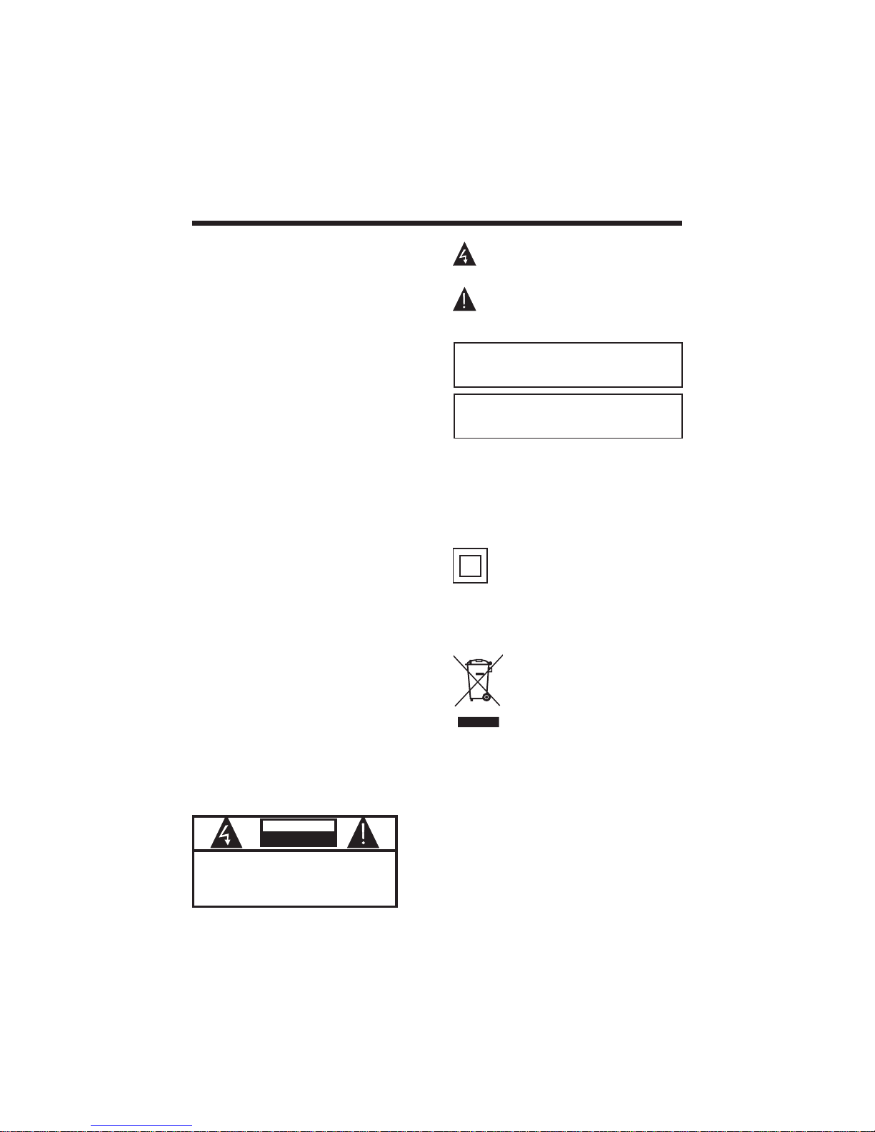
This symbol indic ates th at this product
incorporates double insulation betwee n
hazardous mains voltage and user accessibl e
parts. When servicing use only
identical replaceme nt part s.
This marking indicates that this product should
not be disposed with other household wastes
throughout the EU. To prevent possible harm to
the environment or human health from
uncontrolled waste disposal, recycle it
responsibly to promote the sustainable reuse of
material resources. To return your used device,
please use the return and collection systems or
contact the retailer where the product was
purchased. The y can tak e this pr odu ct for
environmental safe recycling.
TO REDUCE THE RISKOF ELECTRIC SHOCK, DO
NOT REMOVE COVER (OR BACK).NO USER
SERVICEABLE PARTS INSIDE. REFER SERVICING
TO QUALIFIED SERVICE PERSONNEL.
CAU TION
RISKOFELECTRICSHOCK
DONOT OPEN!
CAUT ION
The symbol indicates that dangerous voltages
constituting a risk of electric shock are present
within this unit.
The symbol indicates that there are important
operating and maintenance instructions in the
literaturaccompanying this unit.
To redu ce the ri sk of fire or el ect ric sh ock , do
not expose this apparatus to rain or moisture.
WARNING:
The batteries shall not be exposed to excessive
heat such as sunshine, fire or the like.
WARNING:
Page 7
-3-
High voltages are used in the operation of this television
receiver. Do not remove the cabinet back from your set.
Refer servicing to qualified service personnel.
SA FET Y A ND WARN IN GS
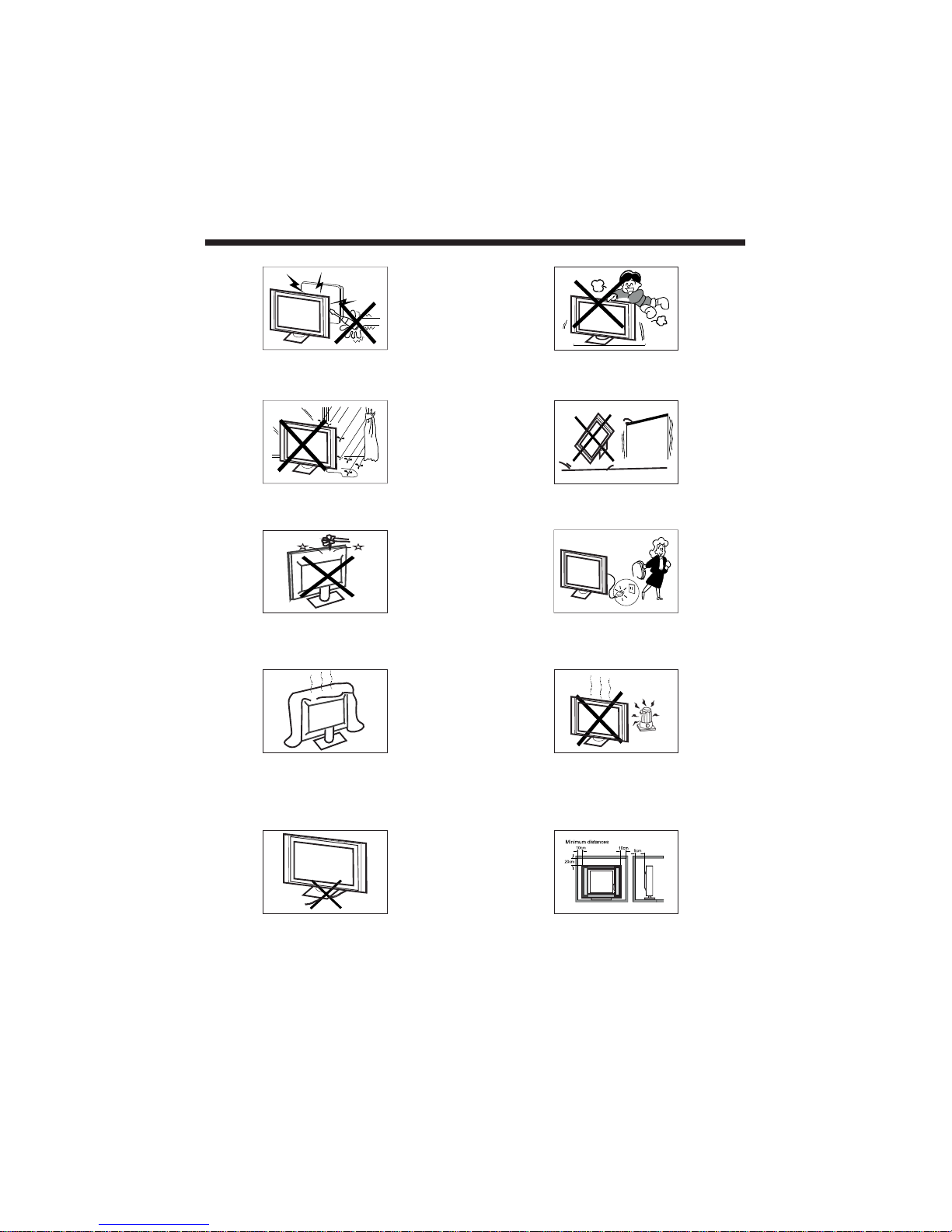
To prevent fire or electrical shock hazard, do not expose
the television receiver to rain or moisture.
Do not drop or push objects into the television cabinet
slots or openings. Never spill any kind of liquid on the
television receiver.
Do not block the ventilation holes in the back cover.
Adequate ventilation is essential to prevent failure of
electrical components.
Do not trap the power supply cord under the television
receiver.
Never stand on, lean on, or suddenly push the television or
its stand. You should pay special attention to children.
Serious injury may result if it falls.
Do not place your television on an unstable cart, stand,
shelf or table. Serious injury to an individual , and damage
to the television, may result if it falls.
Whe n the tele vis ion recei ver is not used for an
ext ended p eri od of time, it is adv isable to di sco nnec t
the AC po wer co rd fro m the AC out let.
Avoid exposing the television receiver to direct sunlight
and other sources of heat. Do not stand the television
receiver directly on other products which give off heat,
e.g. video cassette players and audio amplifiers. Do not
place naked flame sources, such as lighted candles on
the television.
If the television is to be built into a compartment or similar
enclosure, the minimum distances must be maintained. Heat
build-up can reduce the service life of your television, and
can also be dangerous.
Page 8
INTRODU CTION
-4-
Main features
Accessories
Used as Television, display terminal, PC display
High luminance, wide viewing angle
Can store 200 TV programs
HDMI interface
5 Multi-Media player (USB);
Inf rared Re mote Con tro ller.... ....... .
1
Use r s Manual. ... .... ... ....... ....... ... ...1’
Bat tery( AAA). ..... ..... ..... ..... ..... ..... 2
SPECIFICATIONS
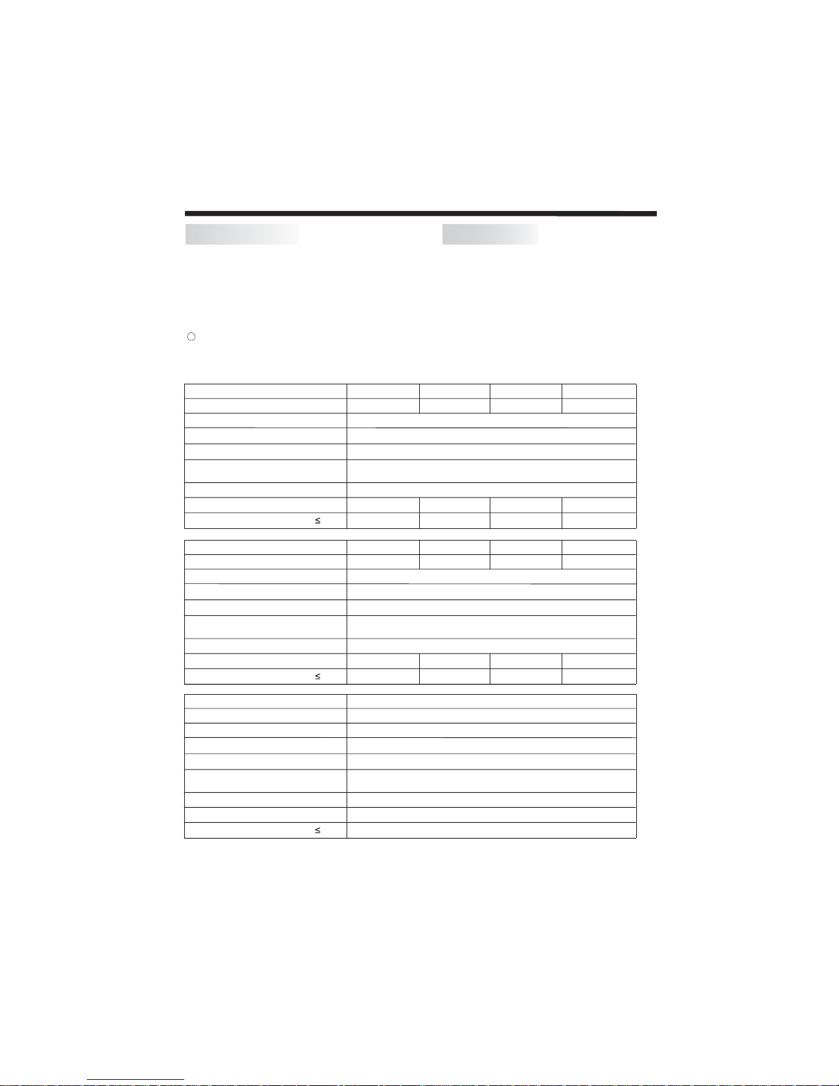
VKC19HH
Viewing Picture Size (Diagonal)
Resolution
Aspect Ratio
TV System
Receiving Channel
Power consumption
Video Signal System
Input Power Voltage
Audio Output Power
1366 x 768
16 : 9
PAL/BG
PAL/NTSC/SECAM
1 TO 200
THD 7 %
2x3W
40W
AC 110-240V 50/60Hz
1366 x 768 1366 x 7681920 x 1080
2x8W
45W 50W 60W
2x3W 2x3W
Viewing Picture Size (Diagonal)
Resolution
Aspect Ratio
TV System
Receiving Channel
Power consumption
Video Signal System
Input Power Voltage
Audio Output Power
1366 x 768
16 : 9
PAL/BG
PAL/NTSC/SECAM
THD 7 %
2x8W
75W
AC 110-240V 50/60Hz
1920 x 1080
100W 125W
1920 x 1080 1920 x 1080
135W
2x8W 2x10W 2x10W
VKC22FH VKC24HH VKC28HH
VKC32HH VKC39FH V KC5 0FH V KC5 5FH
1 TO 200
Viewing Picture Size (Diagonal)
Resolution
Aspect Ratio
TV System
Receiving Channel
Power consumption
Video Signal System
Input Power Voltage
Audio Output Power
1920 x 1080
16 : 9
PAL/BG
PAL/NTSC/SECAM
THD 7 %
2x10W
120W
AC 110-240V 50/60Hz
VKC46FH
1 TO 200
Page 9
-5-
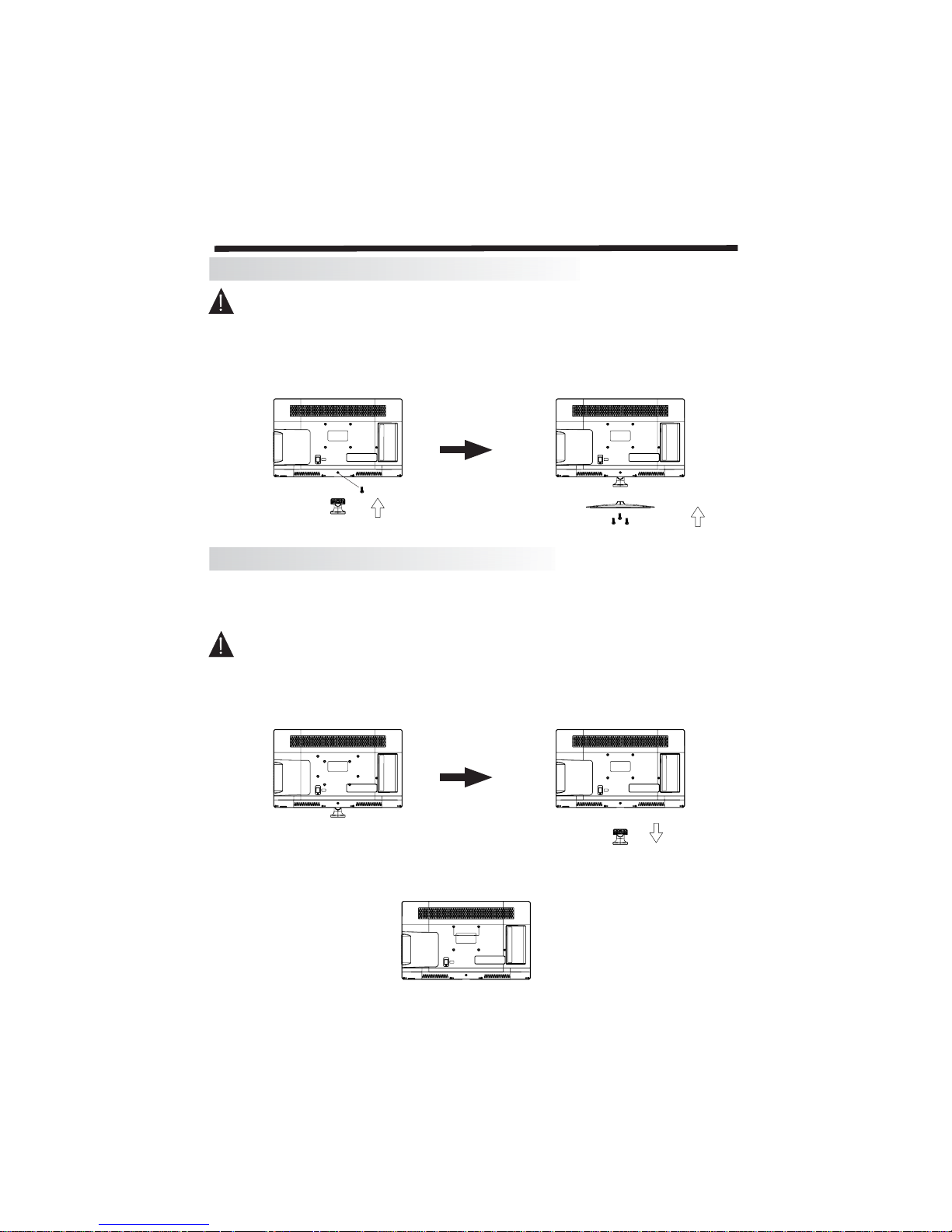
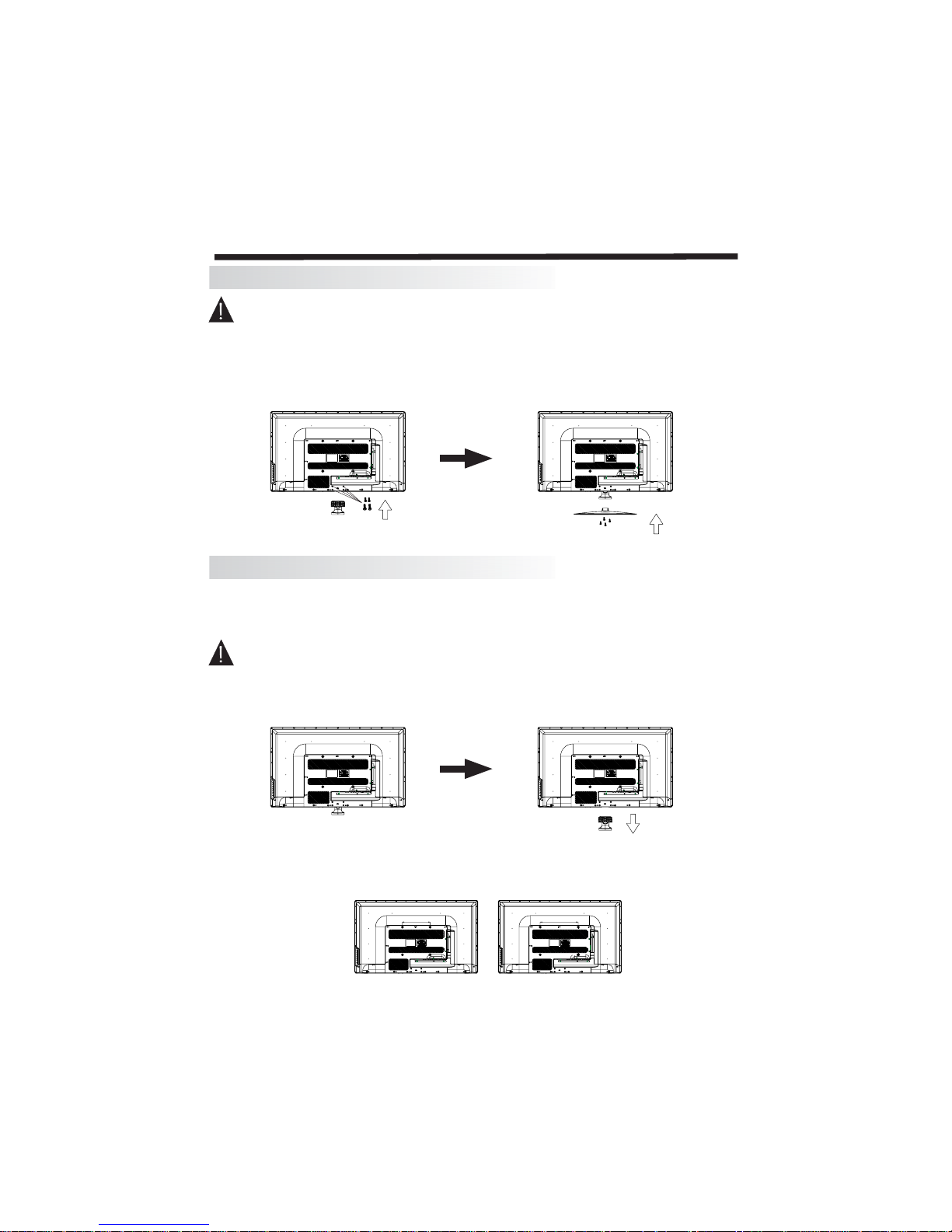
Install ation of St andbase As sembly(19"/2 2"/24")
Prepare to place the TV wi th the di spl ay sid e do wn on a fla t su rfa ce. Due to the size and wei ght of thi s
TV, the us e of 2 peo ple is re com mended wh en moving it. Ensure the table or de sk you us e prov ide s
a flat, totally clea n surf ace , and use a sof t clot h betw een th e face of th e TV and the table to pro tec t the
TV's screen.
1. Locate the bot tom brack et int o the gap in th e bott om of the T V, and ch eck th at it is sec urely hel d in
place by its screws , as per a) bel ow.
2. Gently slide the fitted br ack et at the bo tto m of the TV into the slot in the base stand. Sec ure th e base
stand using the 3 pcs sup pli ed scr ews , as per b) bel ow, and ch eck th at eac h scre w is fir mly ti ghtened.
Installation of WallMount Assembly(19"/22'/24")
For wall mounting with an optional bracket, please read the following instructions in conjunction with the
bracket's instructions. Make sure qualified service personnel perform the operation.
This televisio n can be wall moun ted as f oll ows :
1.Place the LED LCD Tel evi sio n face do wn ont o a sol id surface. Please place some soft mater ial ov er
the front of the screen to pro tec t it fr om any d ama ge. T he LCD pa nel is a fragile component, and must
be suitably protecte d when re mov ing th e base st and . Be sure th at no har d or sh arp objects can come
into contact with the sc ree n's s urf ace . Do not exe rt pre ssu re on the fr ont of the unit at any time, as this
may damage the LCD screen.
2.Remove the 1 scr ews fro m the low er par t of the tel evi sio n, whe re the ba se joi ns to the TV, and take
away the stand (pu t the sta nd and sc rew s som ewh ere sa fe for fu tur e use) .
3.Use the M4 screws pro vid ed to fix th e TV ont o a wall mo unting bracket (not inc lud ed) vi a the
four VESA s tan dar d hole s on the ba ck of th e tele vis ion .
a) b)
INSTALLATION
100mm
Page 10
-6-
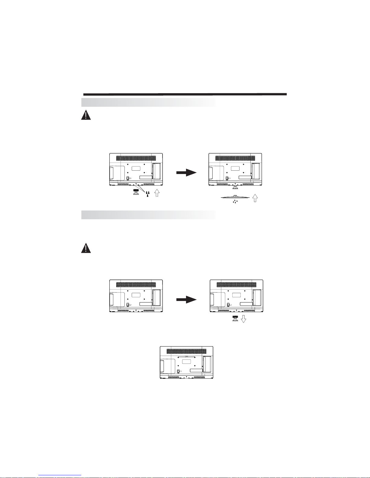
Install ation of St andbase As sembly(28"/3 2")
Prepare to place the TV wi th the di spl ay sid e do wn on a fla t su rfa ce. Due to the size and wei ght of thi s
TV, the us e of 2 peo ple is re com mended wh en moving it. Ensure t he tab le or des k you use pr ovi des
a flat, totally clea n surf ace , and use a sof t clot h betw een th e face of th e TV and the table to pro tec t the
TV's screen.
1. Locate the bot tom brack et int o the gap in th e bott om of the T V, and ch eck th at it is sec urely hel d in
place by its screws , as per a) bel ow.
2. Gently slide the fitted br ack et at the bo tto m of the TV into the slot in the base stand. Sec ure th e base
stand using the 4 pcs sup pli ed scr ews , as per b) bel ow, and ch eck th at eac h scre w is fir mly ti ghtened.
Installation of WallMount Assembly(28"/32")
For wall mounting with an optional bracket, please read the following instructions in conjunction with the
bracket's instructions. Make sure qualified service personnel perform the operation.
This televisio n can be wall moun ted as f oll ows :
1.Place the LED LCD Tel evi sio n face do wn ont o a sol id surface. Please place some soft mater ial ov er
the front of the screen to pro tec t it fr om any d ama ge. T he LCD pa nel is a fragile component, and must
be suitably protecte d when re mov ing th e base st and . Be sure th at no har d or sh arp objects can come
into contact with the sc ree n's s urf ace . Do not exe rt pre ssu re on the fr ont of the unit at any time, as this
may damage the LCD screen.
2.Remove the 3 scr ews fro m the low er par t of the tel evi sio n, whe re the ba se joi ns to the TV, and take
away the stand (pu t the sta nd and sc rew s som ewh ere sa fe for fu tur e use) .
3.Use the M4 screws pro vid ed to fix th e TV ont o a wall mo unting bracket (not inc lud ed) vi a the
four VESA s tan dar d hole s on the ba ck of th e tele vis ion .
a) b)
INSTALLATION
Page 11
-7-
Install ation of St andbase As sembly(40"/ 5 0"/55 ")46"/
Prepare to place the TV wi th the di spl ay sid e do wn on a fla t su rfa ce. Due to the size and wei ght of thi s
TV, the us e of 2 peo ple is re com mended wh en moving it. Ensure t he tab le or des k you use pr ovi des
a flat, totally clea n surf ace , and use a sof t clot h betw een th e face of th e TV and the table to pro tec t the
TV's screen.
1. Locate the bot tom brack et int o the gap in th e bott om of the T V, and ch eck th at it is sec urely hel d in
place by its screws , as per a) bel ow.
2. Gently slide the fitted br ack et at the bo tto m of the TV into the slot in the base stand. Sec ure th e base
stand using the 4 pcs sup pli ed scr ews , as per b) bel ow, and ch eck th at eac h scre w is fir mly ti ghtened.
Installation of WallMount Assembly( 40"/46"/50"/)55"
For wall mounting with an optional bracket, please read the following instructions in conjunction with the
bracket's instructions. Make sure qualified service personnel perform the operation.
This televisio n can be wall moun ted as f oll ows :
1.Place the LED LCD Tel evi sio n face do wn ont o a s oli d surf ace . Pl eas e place some soft material over
the front of the screen to pro tec t it fr om any d ama ge. T he LCD pa nel is a fragile component, and must
be suitably protecte d when re mov ing th e base st and . Be sure th at no har d or sh arp objects can come
into contact with the sc ree n's s urf ace . Do not exe rt pre ssu re on the fr ont of the unit at any time, as this
may damage the LCD screen.
2.Remove the 4 scr ews fro m the low er par t of the tel evi sio n, whe re the ba se joi ns to the TV, and take
away the stand (pu t the sta nd and sc rew s som ewh ere sa fe for fu tur e use) .
3.Use the M6 screws pro vid ed to fix th e TV ont o a wall mo unting bracket (not inc lud ed) vi a the
four VESA s tan dar d hole s on the ba ck of th e tele vis ion .
a) b)
INSTALLATION
400200
Page 12
-8-
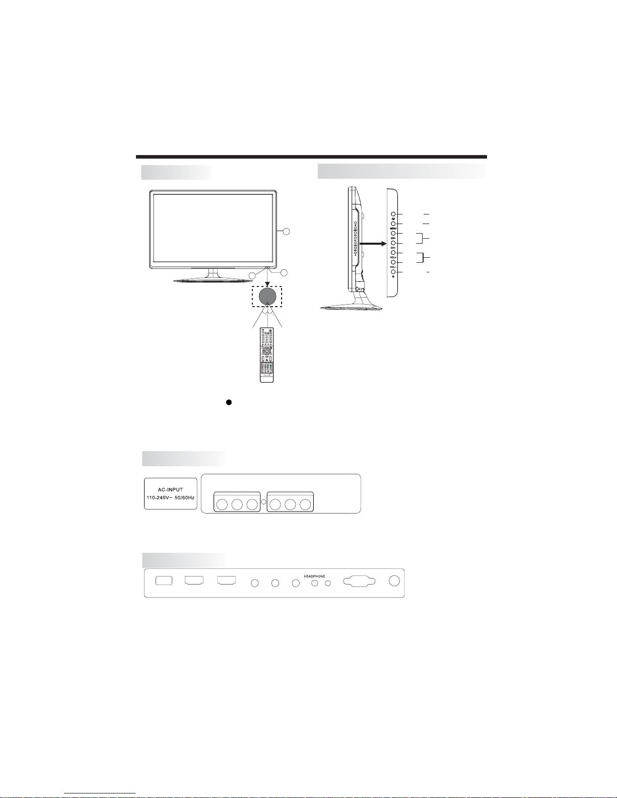
Rear AV Connectivities (19"/22"/24"/28")
All the terminals are(from left to right):
, VIDEO, AUDIO INPUTSAC POWER SOCKET , AV OUTPUT.
Note: VIDEO and YPbPr share one audio channel.
Rear AV side Connectivities(19"/22"/24"/28")
INSTALLATION
Front panel
Key Board Instructions (19" /22" /24" /28")
1: Rem ote cont rol sens or.
2: Ind icato r L ED: RE D STAN DBY.
3: Key bo ard
1 SOURCE
2 MENU
3 CH+/CH-
4 VOL+/VOL-
5. STANDBY
“ ” “ ”
“ ” “ ”
“ ” “ ”
Display the input source menu.
Display main MENU.
In TV mode press CH+ or CH- to change
the channel up and down.
In MENU mode, press CH+ or CH- to select
items.
Adjust sound level.
In MENU mode, press VOL+ or VOL- to
adjust the item that you selected.
Press this button to turn the unit ON from
STANDBY mode.
Press it again to turn the set back to STANDBY.
All the terminals are (from left to right):
USB, HDMI2, HDMI1, YPbPr, HEADPHONE, PC AUDIO, VGA, RF.
Note: When HDMI port get DVI signal, the audio signal receives from the PC
Audio channel.
30 3 0
1
2
3
SOU RCE
MEN U
VOL +
VOL -
CH+
CH-
STAND BY
HDMI 2 HDMI1USB
VGA
RF
Y Pb Pr
PC AUDIO
VIDEO
L R
AV IN
VIDEO
L R
AV OUT
Page 13
-9-
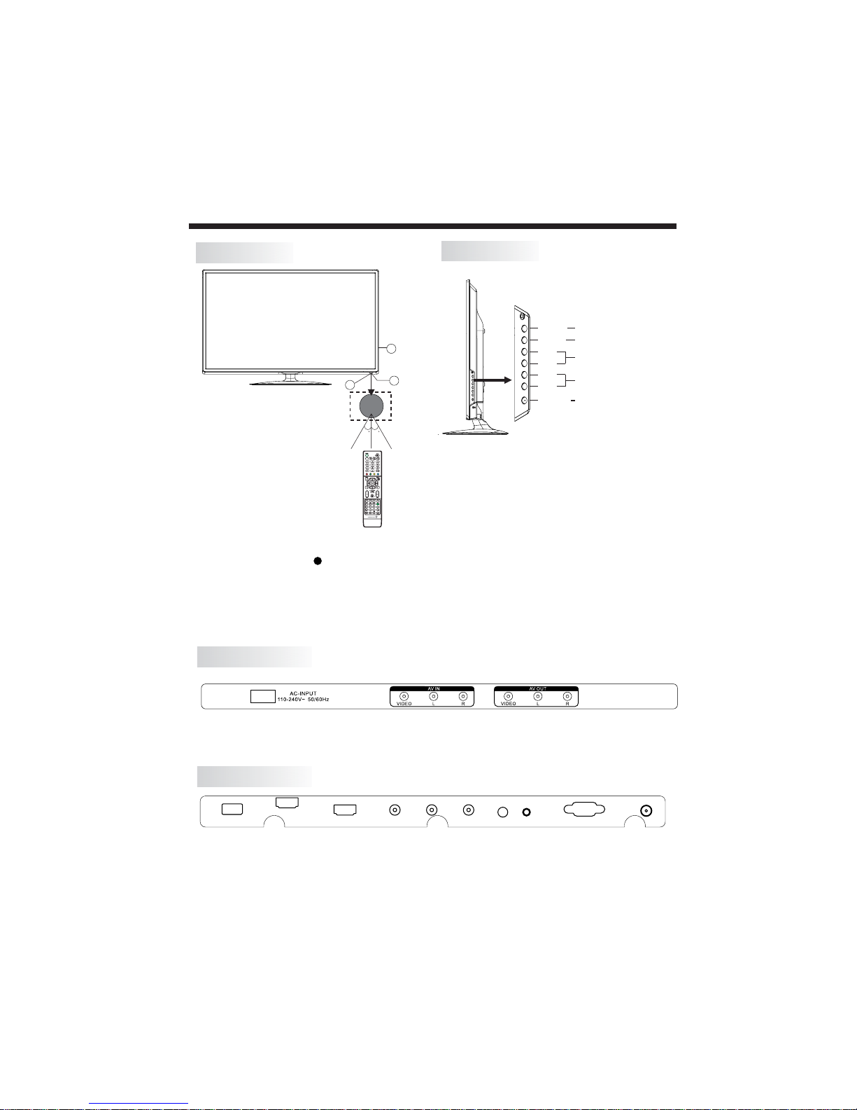
All the terminals are(from left to right):
, VIDEO, AUDIO INPUTSAC POWER SOCKET , AV OUTPUT.
Note: VIDEO and YPbPr share one audio channel.
INSTALLATION
Front panel
Key Board Instructions (32")
1: Rem ote cont rol sens or.
2: Ind icato r L ED: RE D STAN DBY.
3: Key bo ard
1 SOURCE
2 MENU
3 CH+/CH-
4 VOL+/VOL-
5. STANDBY
“ ” “ ”
“ ” “ ”
“ ” “ ”
Display the input source menu.
Display main MENU.
In TV mode press CH+ or CH- to change
the channel up and down.
In MENU mode, press CH+ or CH- to select
items.
Adjust sound level.
In MENU mode, press VOL+ or VOL- to
adjust the item that you selected.
Press this button to turn the unit ON from
STANDBY mode.
Press it again to turn the set back to STANDBY.
All the terminals are (from left to right):
USB, HDMI2, HDMI1, YPbPr, HEADPHONE, PC AUDIO, VGA, RF.
Note: When HDMI port get DVI signal, the audio signal receives from the PC
Audio channel.
30 3 0
1
2
3
SOU RCE
MEN U
VOL +
VOL -
CH+
CH-
STAND BY
HDM I2
HDM I1
USB
VGA
Y
Pb
Pr
HEADPHONE
PC AUDIO
RF
Rear AV side Connectivities(32")
Rear AV Connectivities (32")
Page 14
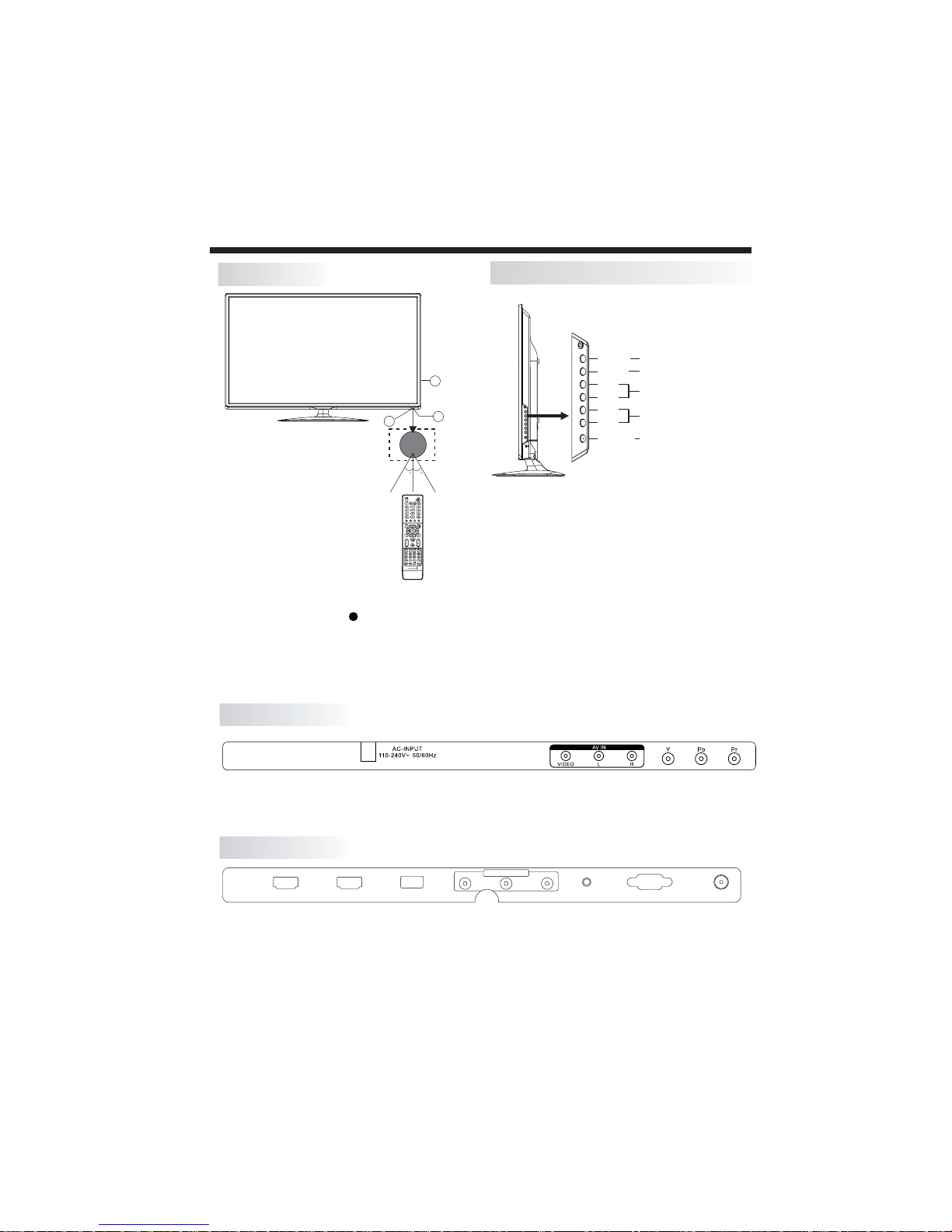
Rear AV Connectivities ( )40"/46"/50"/55"
All the terminals are(from left to right):
, VIDEO, AUDIO INPUTSAC POWER SOCKET , YPbPr.
Note: VIDEO and YPbPr share one audio channel.
Rear AV side Connectivities( )40"/46"/50"/55"
INSTALLATION
Front panel
Key Board Instructions ( )40"/46"/50"/55"
1: Rem ote cont rol se nsor.
2: Ind icato r L ED: RE D STAN DBY.
3: Key bo ard
1 SOURCE
2 MENU
3 CH+/CH-
4 VOL+/VOL-
5. STANDBY
“ ” “ ”
“ ” “ ”
“ ” “ ”
Display the input source menu.
Display main MENU.
In TV mode press CH+ or CH- to change
the channel up and down.
In MENU mode, press CH+ or CH- to select
items.
Adjust sound level.
In MENU mode, press VOL+ or VOL- to
adjust the item that you selected.
Press this button to turn the unit ON from
STANDBY mode.
Press it again to turn the set back to STANDBY.
30 3 0
1
2
3
SOU RCE
MEN U
VOL +
VOL -
CH+
CH-
STAND BY
All the terminals are (from left to right):
HDMI2, HDMI1, USB, AV OUTPUT, PC AUDIO, VGA, RF.
Note: When HDMI port get DVI signal, the audio signal receives from the PC
Audio channel.
AV OUTPU T
HDM I2 HDM I1 USB RFVGAPC AUD IOVID EO L R
-10-
Page 15
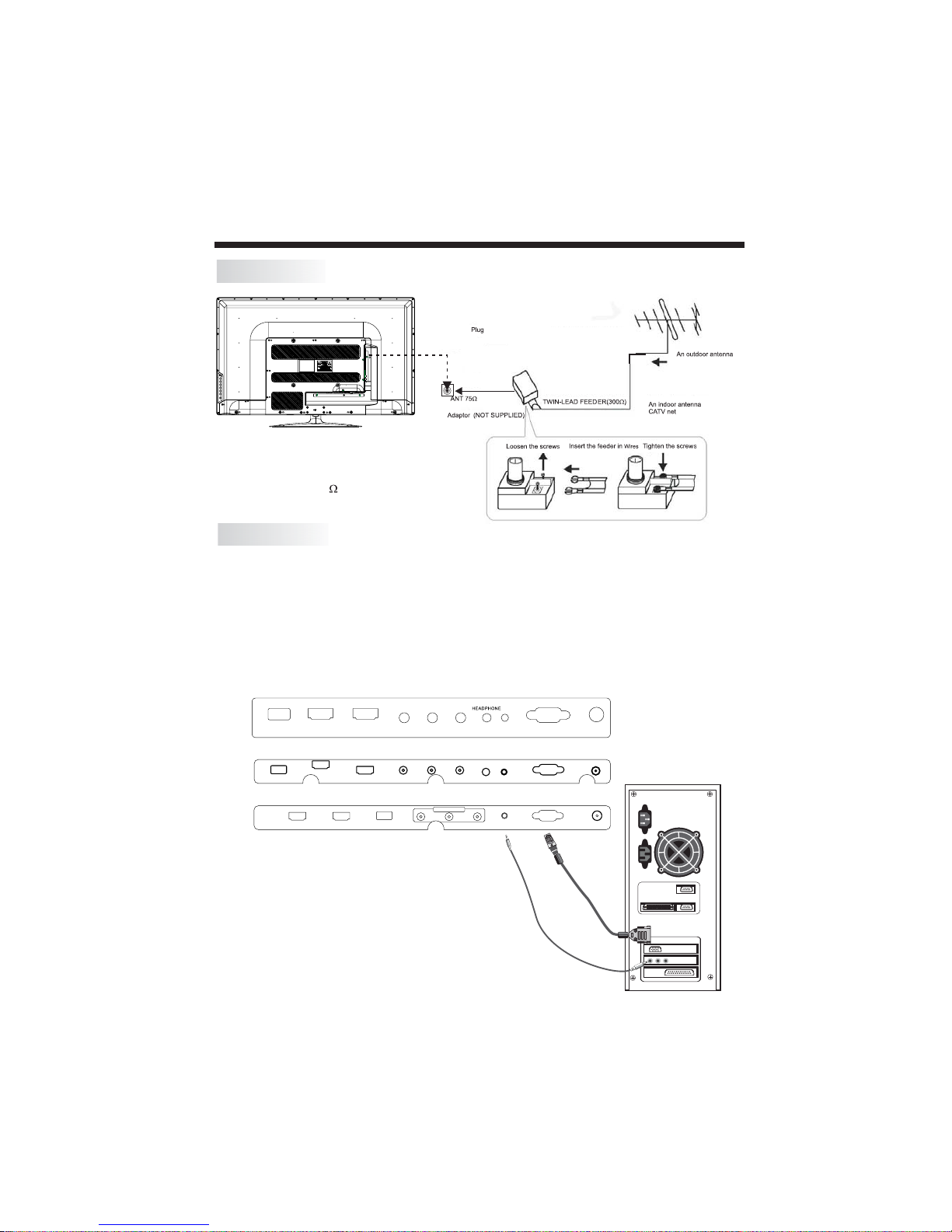
INSTALLATION
-11-
STEPS:
PC Connectivity
Be sure bot h the TV an d computer are se t to Powe r off.
1.Con nect VGA an d audio cable.
2.Con nect the power co rd.
3.Pow er on the TV, switch to PC mo de.
4.Pow er on the PC.
This seq uen ce is very imp ortant.
Note:
Aerial connections: IEC(female).
Input impendance: 75 unbalanced.
ANTENNA
HDMI 2
HDMI 1
USB
VGA
Y
Pb
Pr
HEADPHONE
PC AUDIO
RF
AV OUTPUT
HDMI2 HDMI1 USB RFVGAPC AUDI OVIDE O L R
HDMI2 HDMI1USB
VGA
RF
Y Pb Pr
PC AUDIO
FOR 19"/22"/24"/28"
FOR 32"
FOR 40"/46"/50"/55"
Page 16
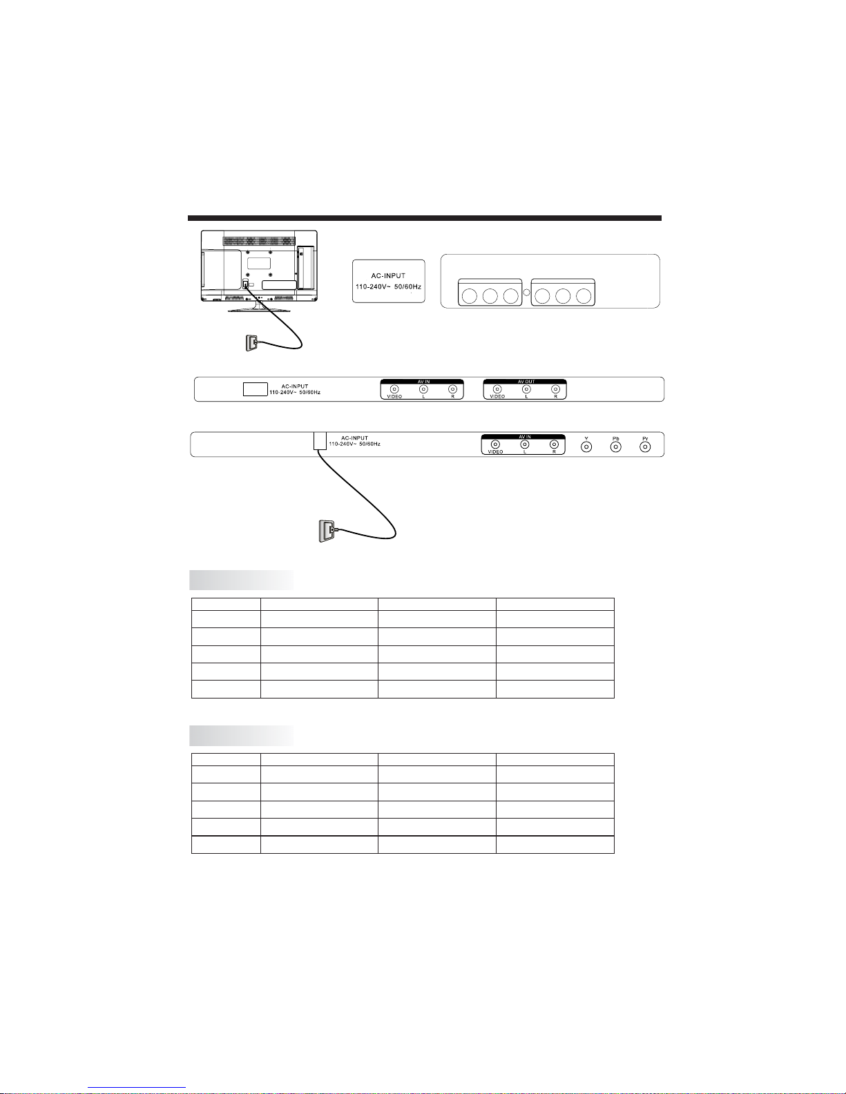
INSTALLATION
-12-
PRESET MODE (PC)
NOTE: PC V.Freq.(Hz) not more than 60Hz.
1
2
3
800*600
1024*768
60
60
37.88
48.36
RESOLUTION
V.Freq.(Hz) H.Freq.(KHz)
1360*768
60
47.7
4
1280*768
60
47.3
PRESET MODE (HDMI)
1
2
3
800*600
1024*768
60
60
37.88
48.36
RESOLUTION
V.Freq.(Hz) H.Freq.(KHz)
1360*768
60
47.7
4
1280*768
60
47.3
5
1920*1080
60
67.5
5
1920*1080
60
67.5
(Only for 22"/40"/ 50"55")46"/
(Only for 19"/24"/28"/32")
VIDEO
L R
AV IN
VIDEO
L R
AV OUT
FOR 19"/22"/24"/28"
FOR 32"
FOR 40"/46"/50"/55"
Page 17
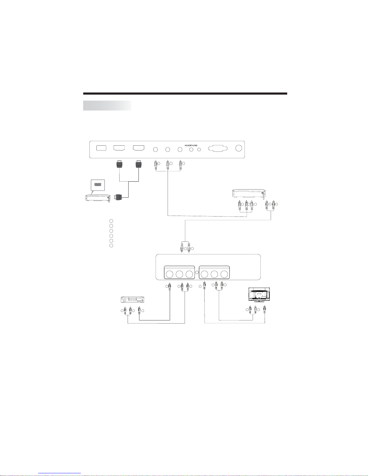
It can be connected to the following appliances: VCR, multi disc player, DVD, camcorder,
video game or stereo system, etc.....
YPbPr can support these video formats:480i,576i,480p,576p,720p,1080i,1080P.
INSTALLATION
This TV provides one group of AV, one group of YPbPr for convenient connection to VCR, DVD
or other video equipment. Please refer to the owner's manual of the equipment to be connected
as well.
You can use the input terminals on TV set rear as follows.
AV Equipments for 19"/22"/24"/28"
-13-
Note:
1.VIDEO and YP bPr sh are on e audi o chan nel .
2.When HDMI port get DVI sign al, th e "PC Aud io" ch ann el is cha nge d to rece ive th e au dio for HD MI port.
3.Sometimes it wil l not sup por t in diff ere nt device because the device suppl ys non sta nda rd sig nal .
4.When curren t sour ce is TV, AV OUT signal is TV; when current sourc e is AV, AV O UT si gna l is AV;
other source s have no AV OUT s ignal.
W R
GBR
VIDEO EQUIPMENT with YPbPr
W
R
W
R
W R
TO AUDIO OUTPUTS
VIDE O EQUIPM ENT
TO VIDEO
OUTPUTS
Y
Y
Red (audio R)
White(audio L)
R
Red(Pr or Cr)
W
R
Blue(Pb or Cb)
B
Green(Y)
G
Yellow (video)
Y
W
R
W R
TO AUDIO INPUTS
VIDE O EQUIPM ENT
TO VIDEO
INPUTS
G B R
Y
HDMI
HDMI 2 HDMI1USB
VGA
RF
Y Pb Pr
PC AUDIO
VIDEO
L R
AV IN
VIDEO
L R
AV OUT
Page 18
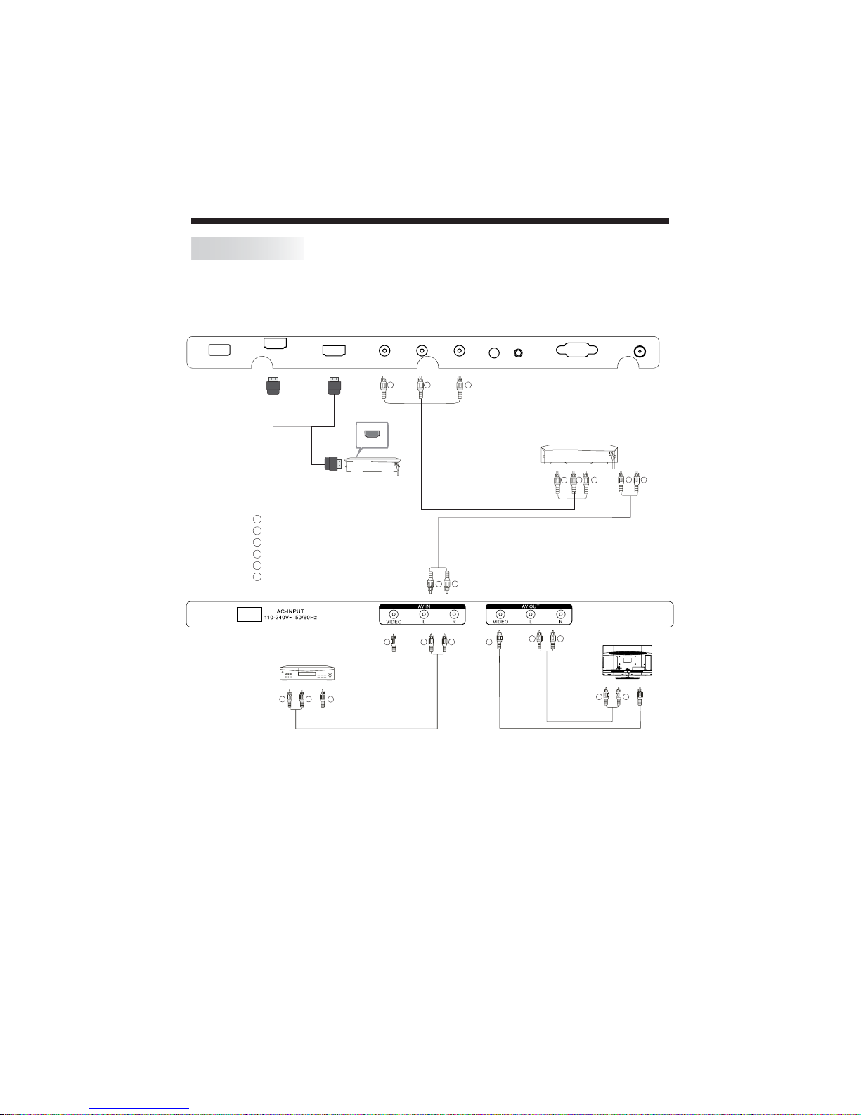
It can be connected to the following appliances: VCR, multi disc player, DVD, camcorder,
video game or stereo system, etc.....
YPbPr can support these video formats:480i,576i,480p,576p,720p,1080i,1080P.
INSTALLATION
This TV provides one group of AV, one group of YPbPr for convenient connection to VCR, DVD
or other video equipment. Please refer to the owner's manual of the equipment to be connected
as well.
You can use the input terminals on TV set rear as follows.
AV Equipments for 32"
-14-
Note:
1.VIDEO and YP bPr sh are on e audi o chan nel .
2.When HDMI port get DVI sign al, th e "PC Aud io" ch ann el is cha nge d to rece ive th e au dio for HD MI port.
3.Sometimes it wil l not sup por t in diff ere nt device because the device suppl ys non sta nda rd sig nal .
4.When curren t sour ce is TV, AV OUT signal is TV; when current sourc e is AV, AV O UT si gna l is AV;
other source s have no AV OUT s ignal.
W R
GBR
VIDEO EQUIPMENT with YPbPr
W
R
W
R
W R
TO AUDIO OUTPUTS
VIDE O EQUIPM ENT
TO VIDEO
OUTPUTS
Y
Y
Red (audio R)
White(audio L)
R
Red(Pr or Cr)
W
R
Blue(Pb or Cb)
B
Green(Y)
G
Yellow (video)
Y
W
R
W R
TO AUDIO INPUTS
VIDE O EQUIPM ENT
TO VIDEO
INPUTS
G
B
R
Y
HDM I2
HDM I1
USB
VGA
Y
Pb
Pr
HEADPHONE
PC AUDIO
RF
HDMI
Page 19
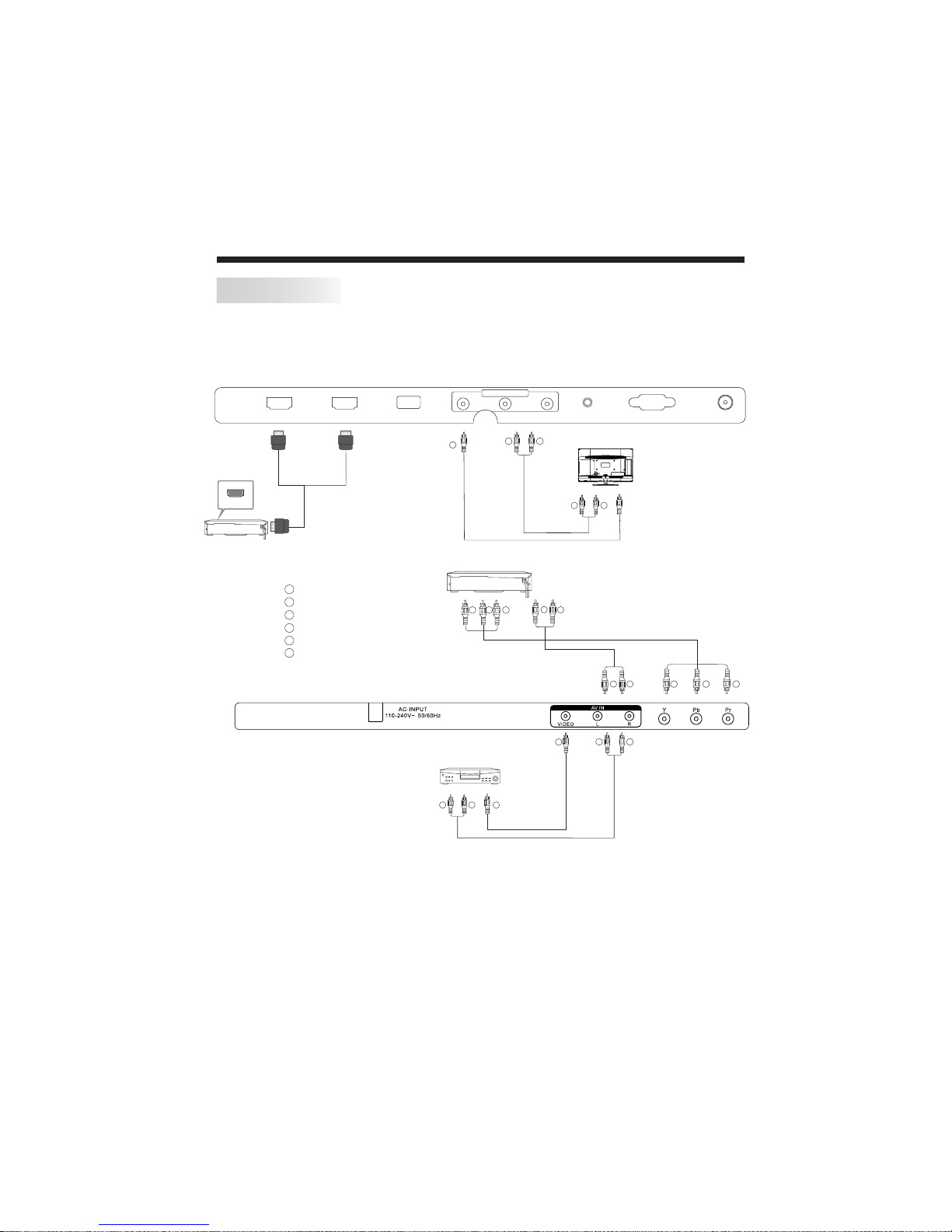
It can be connected to the following appliances: VCR, multi disc player, DVD, camcorder,
video game or stereo system, etc.....
YPbPr can support these video formats:480i,576i,480p,576p,720p,1080i,1080P.
INSTALLATION
This TV provides one group of AV, one group of YPbPr for convenient connection to VCR, DVD
or other video equipment. Please refer to the owner's manual of the equipment to be connected
as well.
You can use the input terminals on TV set rear as follows.
AV Equipments for 40"/ 50"/55"46"/
-15-
Note:
1.VIDEO and YP bPr sh are on e audi o chan nel .
2.When HDMI port get DVI sign al, th e "PC Aud io" ch ann el is cha nge d to rece ive th e au dio for HD MI port.
3.Sometimes it wil l not sup por t in diff ere nt device because the device suppl ys non sta nda rd sig nal .
4.When curren t sour ce is TV, AV OUT signal is TV; when current sourc e is AV, AV O UT si gna l is AV;
other source s have no AV OUT s ignal.
W R
GBR
VIDEO EQUIPMENT with YPbPr
W
R
W R
TO AUDIO OUTPUTS
VIDE O EQUIPM ENT
TO VIDEO
OUTPUTS
Y
Y
Red (audio R)
White(audio L)
R
Red(Pr or Cr)
W
R
Blue(Pb or Cb)
B
Green(Y)
G
Yellow (video)
Y
W
R
W R
TO AUDIO INPUTS
VIDE O EQUIPM ENT
TO VIDEO
INPUTS
Y
G
B
R
W
R
HDMI
AV OUTPU T
HDM I2 H DMI1 USB RFVGAPC AUD IOVID EO L R
Page 20
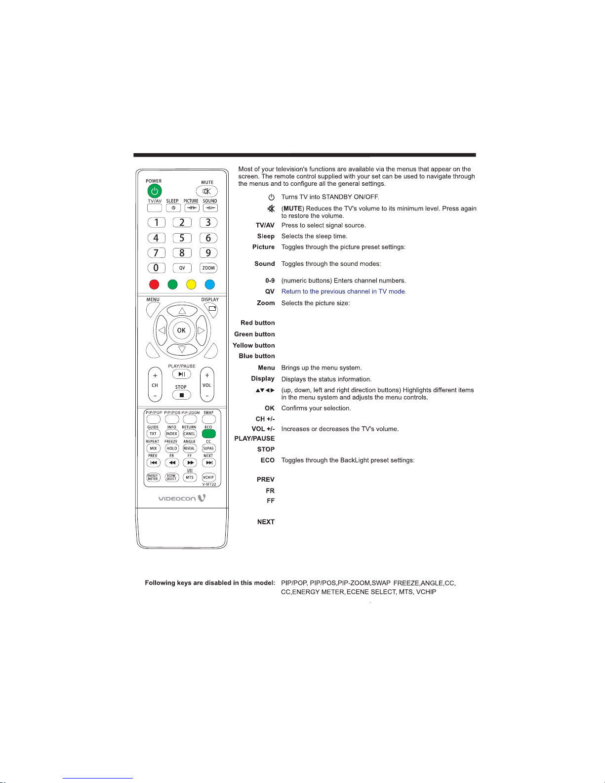
REMOTE CONTROLLER
-16-
Standard, Mil d, Use r,
Dynamic.
Standare Music Mo vie, , ,
Sports User.,
Auto, 4:3, 16:9, Zoom , Pano ram a.
Press CH+ or CH- to go to the next or previous channel.
In USB mode, used as Play/Pause key.
In USB mode, used as Stop key.
In USB mode, used as Previous key.
In USB mode, used as reverse key.
In USB mode, used as forword key.
In USB mode, used as Next key.
Favorite pro gra m hotk ey .
Favorite pro gra m hotk ey .
Favorite pro gra m hotk ey .
Favorite pro gra m hotk ey .
RETURN
REPEAT
Under USB channel, switch to play mode.
Under differ ent ch ann els , opti ona l sc ali ng mode is differ ent .
High, Mid, Low.
OFF, Audio Only,
,
Use this key to return to main multimedia menu while
playing a track/item.
Under HDMI channel, when "HDMI CEC" function set as"open", PLAY/PAUSE STOP PREV NEXT
FF FR will play function accordingly.
、 、 、 、
GUIDE
、
When playing the multimedia file, press [GUIDE] key. The task bar
will show for guiding the Multimedia. Under HDMI channel, when
"HDMI CEC" function set as"open" used as "ROOT MENU" key.,
Page 21
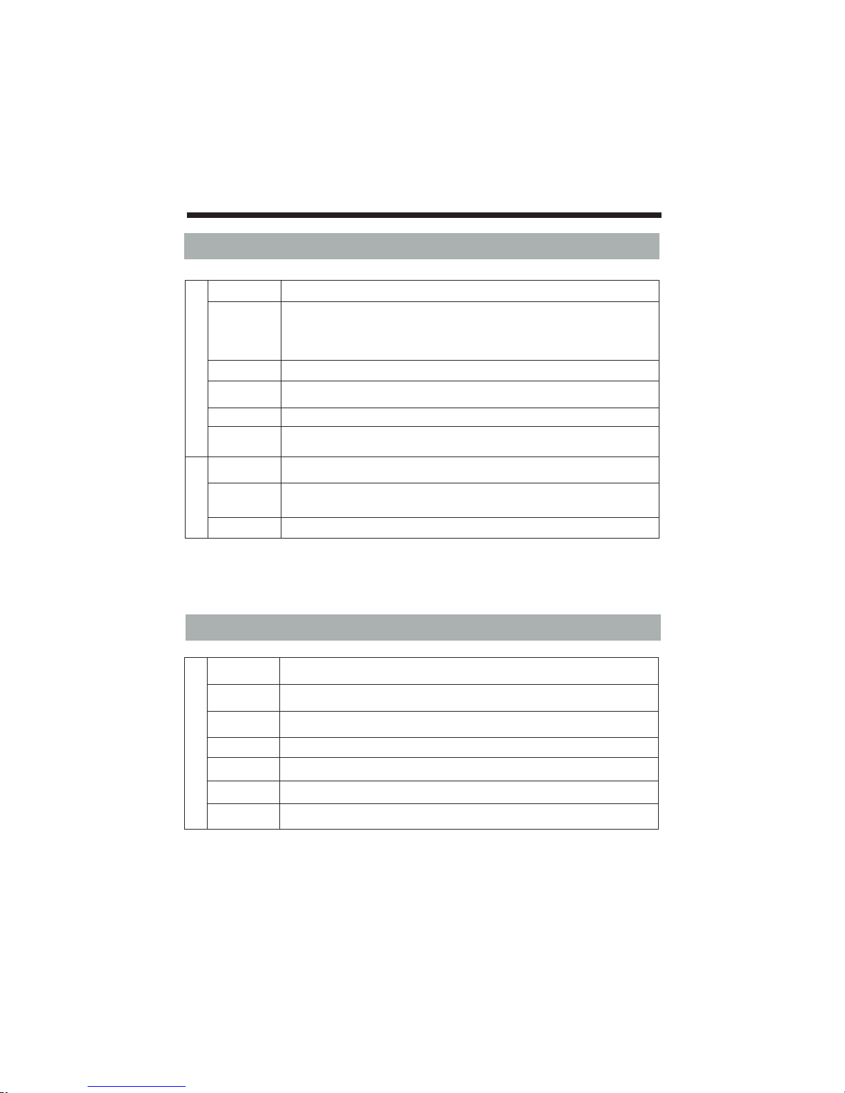
TV OPERATION
-17-
1.PICTURE MENU
PICTURE
Picture Mode Th is fun ctio n is used to se lect the pr ese t picture set tings. (St and ard/ Mil d/Us er/Dy namic )
Con trast
Bri ghtne ss
Col or
Sha rpnes s
Tin t
The se setti ngs are use d to adju st the Contra st (0-100) , Brig htne ss (0-10 0),
Col or (0-10 0), Shar pness (0 -100) , a nd Tin t (0-100 ) valu es for fine ad jus tments of the pi cture.
NOT E: Tint is ena ble d for NTSC cha nne ls only.
Col or Temp. U se thi s option to se lect and cha nge co lor temper ature.
Aspect Ratio
Select the picture size:Auto 4:3 16:9 Zoom Panorama. Under different channels,
optional scaling mode is different
、 、 、 、
。
Blu e Screen T his fu ncti on is use d to ON/OFF the blu e back in no Si gnal co ndi tion.
Noi se
Red uctio n
The DN R ( Off/ Low /Middle /High) red uce th e noise by app lyi ng temp ora l and spatial no ise
red uctio n filte rs to Vide o data.
S
c
r
e
en
Aut oA dju st
Aut o s ett ing all ows th e PC scree n o f TV to sel f adju st. Th is auto matic all y sets the Hor izo ntal
pos ition Ver tic a- posi tio n, Phase and Siz e.、
Hor izont al
Pos .Vertica l Pos.
If pic ture is not Ok wi th aut o setting the n adjust Hori zon tal pos iti on(0 -100) / Vert ical
pos ition (0 -10 0) manuall y to adjust the des ire d pictur e sett ings .
Siz e Ph ase、
Adj ust the pha se (0- 100) and si ze( 0-100) to rem ove or reduce pi ctu re nois e.
Not e : 1) The sc reen m enu w ill be e nab led for PC so urce o nly.
2.SOUND MENU
SOUND
Sound Mode This function is used to select the preset sound modes(User, Standard, Music, Movie,Sports).
EQ
The Eq uiliz er 120Hz, 50 0Hz , 1.5KH z, 5KHz, 10 KHz, (0- 100) can be ch ang ed by other user.
Treble Th e tre ble funct ion is used t o var y the tr ebl e level fro m 0 - 100.
Bal ance Use r can select the le ft/ righ t spea ker int ensit y b y chan ging ba lan ce (-50 - +50 ).
Volume
The main speaker volume can be adjusted by varying this volume bar (0-100).
Aut o Volu me
Thi s f unc tion is us ed to for au toma tic adju stm ent of volume le vel(On/ Off) .
Bas s
The b ass fun ction i s used to v ary t he bass lev el fr om 0 - 100 .
Page 22
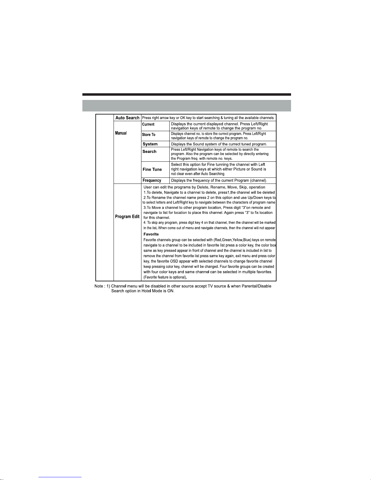
TV OPERATION
-18-
3. CHANNEL MENU
CHA
N
N
EL
Tuning
CH
CH
Page 23
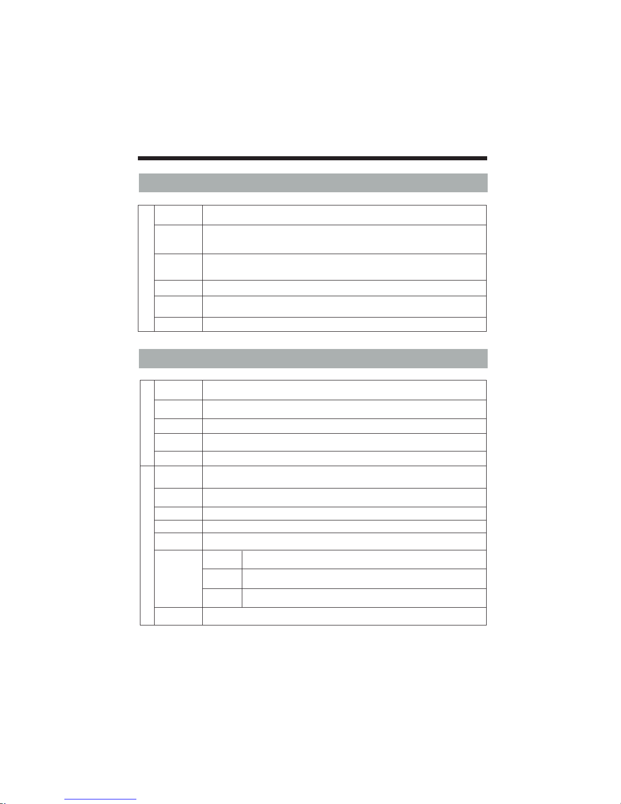
4. SETTING MENU
SETTING
Bac k L igh t
The backlight value can be varied (0-10) This function is used to adjust
brightness level of panel .
Eco visio n
TV is in No rmal sta te when thi s is on, to sav e the power cons umed by TV s elec t p owe r saving
mod es Power Sa ving Off /Low/Mi d/H igh/ Aud io only mod e. in Aud io Only mod e only au dio
is On a nd Pict ure is of f.
HDM I C EC
Thi s f eat ure ope rat es only in HD MI sourc e. If a CEC compli ant de vice li ke Hom e theat er
or DVD pl ayer is con nec ted to TV i n HDMI mode , then th e Playe r c ont rols ca n be oper ated
thr ough TV Remot e.
OSD Du ratio n
Adj ust disp lay ti me of menu
Sof tware
Upd ate(U SB)
Thi s i s for LCD TV S oftware up date. (For Se rvi ce only )
Res et
Sel ect this op tio n to reset all Fe atu re, Audio, Vid eo param ete rs to Default va lue
TV OPERATION
-19-
5. PARENTAL MENU
Parental
Control
Par ent Lock
Swi tch
Mak e t his sw itch On to Ac tiv ate the Pa renta l Cont rol option s selected by us er . When Sw itc h
is Off th e Parental Co ntr ol, its op tio ns will not Op era te.
Set Pa sswor d
Sel ect this op tio n to change the pas sword (def aul t - 0000 ) Ente r n ew
pas sword an d c onfi rm the sam e.
,ma ster pas sword is 82 02
Cha nnel Loc k Press DI GIT KE Y 2 key to Lo ck/Un loc k the channel s (1-200).
Source Lock
Pre ss OK key to Lock /Unlo ck the Sour ces (TV/ AV /YP BPR /HDM I1/HD MI2
PC/ USB). Se lect the so urc es to be locked wit h left/rig ht key on a rem ote.
Clean All
Select this option to reset all Parental options to default value.
Hot el Mode
Swi tch
Mak e t his sw itch On to Ac tiv ate the Ho tel Mode op tio ns selecte d by user .When Swi tch is
Off th e Hotel Mode, its op tions will no t Oper ate.
Hotel Mode
Control
Set Password
Sel ect this op tio n to change the pas sword (def aul t - 0000 ) Ente r new
pas sword an d c onfi rm the sam e.
,ma ster pas sword is 82 02
Key Lo ck
Dis able Sea rch
Max Volu me
Pow er On Set
Sel ect this op tio n On, panel keys wi ll not operat e.
Mak ing this op tio n On, the search op tions/T V menu wi ll be dis abled for use r.
The ma in volum e is limi ted by settin g MAX volume (0- 100 ), User ca nnot
inc rease th e main vo lume gre ate r than MAX vol ume se lect ed.
Pow er On
Sou rce
Power On
Cha nnel
Pow er On
Vol
Sel ect the pow er on sourc e ( TV/ AV/Y PBPR/HD MI1 /HDM I2/ PC/USB) , after
the T V ON, the po wer on so urce wi ll be sam e as specified he re
Sel ect the pow er on cha nnel (1- 200 ), after the TV ON , the cha nnel wil l b e same
as spe cified he re.
By set ting the po wer on vo lume (0- 100 ), this vol ume wi ll be set aft er set gets ON .
Cle ar All
Sel ect this op tio n to reset all Ho tel Mo de options to de fault.
Page 24
TV OPERATION
-20-
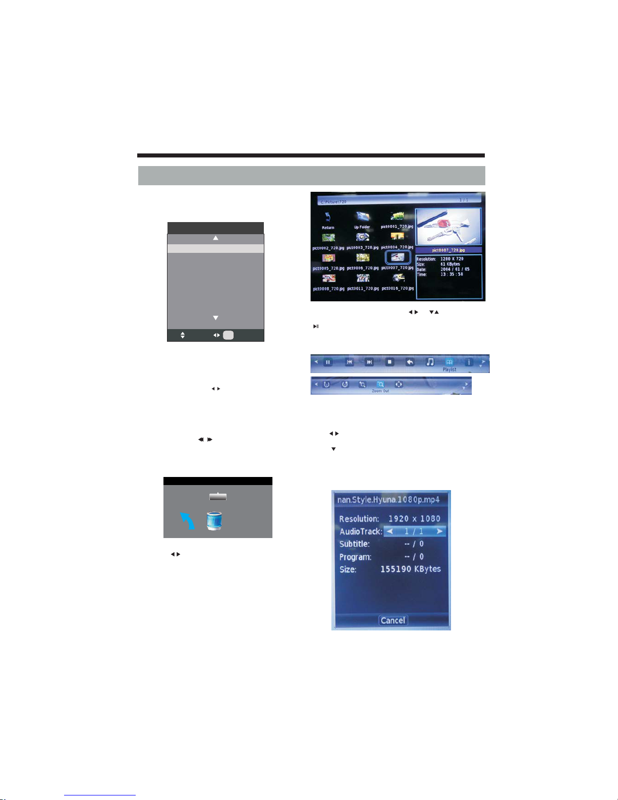
You must en ter the Sou rce me nu first, then ch oice the
USB a nd pres s OK butt on, the U SB menu w ill app ear.
Ple ase make su re tha t the USB device ha ve plugged in
the sl ot. The re are four type me dia item can be sel ect ed,
suc h a s phot o, musi c, Mov ie and tex t. Selec t the ty pe
med ia item b y pre ssing , pre ss bu tto n to enter
the di sk selec tio n menu.
In the mo vie mode , when yo u use FB, FF functi on, Th e
aud io may be paus e in seve ral second s to synchron ize
the au dio an d vide o signal.
In te xt mode , press t o make pa ge up a nd page dow n.
NOT E:
Whe n t he USB de vice is n't su ppor ted, it may be th at the
pow er of the USB dev ice isn' t e nou gh.
OK
sig nal
6. USB FUNCTION
Inp ut Sourc e
PC
HDM I1
USB
HDM I2
TV
YPB PR
AV
Sel ect
OK
OK
Retu rn (C:)
1/1
Pre ss the to s elect t he righ t dis k and press to
dis play med ia file s and folder lis t or choose Retu rn to
bac k t o the med ia type se lec tion me nu.
OK
Sel ect the m edi a file by pre ssi ng or , th en
the p revie w frame w ill p op up. Pres s the b utto n
to pl ay the me dia fi le in fu ll screen . When t he
med ia file (photo , music, Mov ie or tex t type) is
pla ying, pr ess the o r Info bu ttonOK can di splay th e
con trol bar.
Mus ic func tion ne ed to put m usi c and pictu re in the
sam e f old er.
Pre ss to selec t t he fun ctio n icon , press OK but ton to
con firm the fun cti on.
Pre ss or EXI T button to e xit t he con tro l bar.
You can adj ust th e audio tra ck, su btitle, or pr ogram in
the I nfo men u while P lay ing the vid eo fi le.
Cho ose the Inf o i con an d press OK can di spl ay the Inf o
MEN U.
NOT E:
Page 25
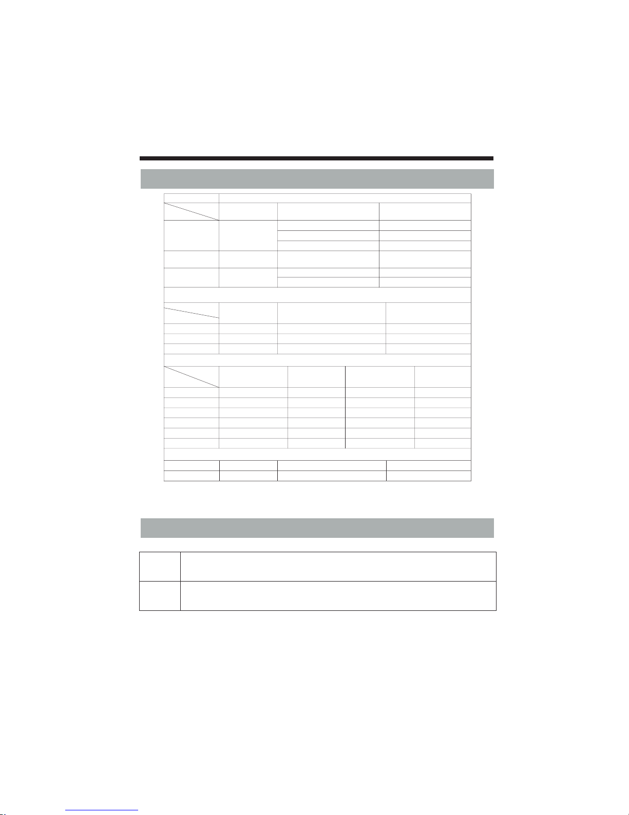
Fil e t ype
Pho to
Res oluti on Com press ion Opti on Sup port ran ge
Bas eline (Stan dard)
JPE G
153 60x86 40
Bas eline ha s been optimiz ed
Pro gress ive JPEG
Resolution Only Support1024x768
Sup port
960 0x640 0
BMP
PNG
960 0x640 0
Monochromatism,16color,256color,
16bit,24bit,32bit
Resolution Only Support 1200x800
Aud io
Sam pling ra te
Bau d r ate
Cha nnel
MP3
WMA
M4A (AA C)
Vide o Su ppor t Di splay the .sr t. sub titl e on the vid eo imag es( . sr t )
Int ernal en cod ing
MPE G1
.DAT /.MPG/. MPEG
MPE G2
.MP G
MPE G4
.AVI /.MP4
RM/ RMV B
.RM /.R MVB
MKV
.MK V/. MOV
MJP EG
.AVI
/
/
XVI D
RV8 ,RV9 ,RV10
MPE G1, 2,4
192 0X1 080 @ 30P
640 X48 0 @ 3 0P
Top20 Mbp s
Top20 Mbp s
Top20 Mbp s
Top10 Mbp s
Top20 Mbp s
Top10 Mbp s
Text
Par amete r File s
Fil e s uffix es
Cha racte r sets
Fil e S ize Su ppor ted
Text
.tx t
ANS I /UNI CODE /GB
Max 3M B
1920X1080 @ 30P
1920X1080 @ 30P
1920X1080 @ 30P
1920X1080 @ 30P
Non -inte rla ced
Int erlac e
Sup port
Sup port
Sup port
Fil e t ype
Fil e t ype
Ass ociate d
par ameter s
Fil e s uffix es
Res oluti on
Bau d r ate
Mon o Ste reo,
Mon o Ste reo,
Mon o Ste reo,
32K 3 20K bps
32K 3 20K bps
32K 3 20K bps
32K 4 8KH z
8K 48 KHz
8K 48 KHz
TV OPERATION
-21-
Multimedia (USB) le support
Resolution Support
YPbPr
mode
HDM I
480 i ( 60H z), 480 p (60H z), 576i (50H z), 576p (50H z), 72 0p (50H z, 60H z),1080 i (50H z, 60Hz )
480 i ( 60H z), 480 p (60H z), 576i (50H z), 576p (50H z), 72 0p ( 60Hz), 108 0i (50H z, 60H z)
108 0P (50 Hz, 60H z)
Ass ociate d
par ameter s
Ass ociate d
par ameter s
Page 26
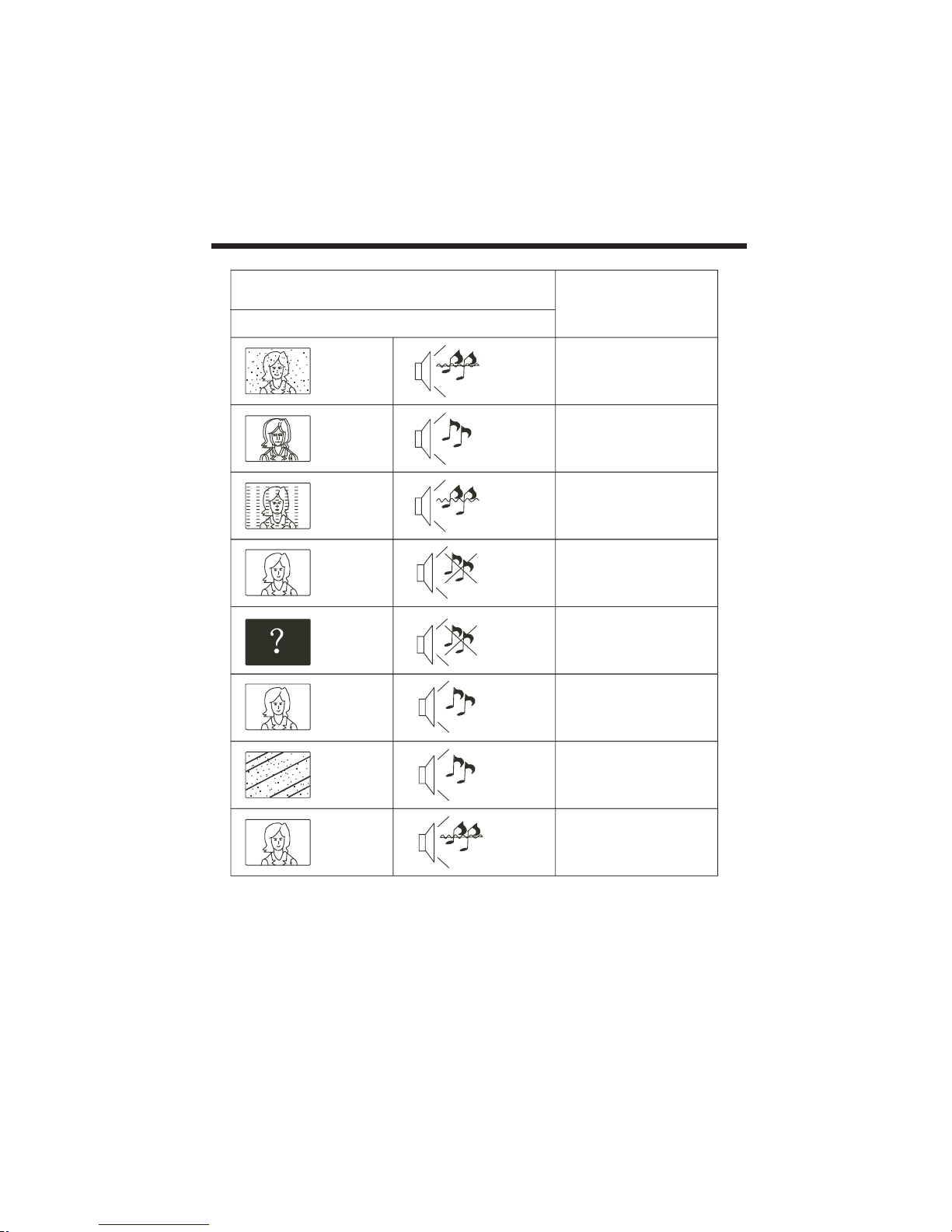
Picture Audio
Snow Noise
ant enna pos iti on, direct ion
or con necti on
Inspection
Interf ere
Noise
ele ctron ic equ ipment, car/
mot orcyc le, fluoresc ent light
Normal Pi ctu re
Mute
Volum e(in spe ct wether the
mut e f unc tion on th e remo te
con trol are st art ed , or audio
sys tem are cor rec t or not)
No pictur e Mute
Pow er cord is not in serte d
Pow er switc h i s not ope ned
Con trast an d b rig htne ss/ volume
set up
Pre ss stand by key on the rem ote
con trol for in spe cting
No color Normal audio co lor cont rol
Scramb le
Normal au dio
or weak
ret une chan nel
No color
Noise
Aud io syste m
Special Exp lan ati on The accessories such as remote control is not belongs to the guarantee
Normal au dio
ant enna pos iti on, direct ion
or con necti on
Trouble phenomenon
Ghost
-22-
TR OUB LE SHOOT ING
Page 27
Page 28
LED
LED
T
V set.
LE
D
LED
TV s
et.
Page 29
Page 30
Page 31
Page 32
LEDT
V
V
KC-
VID
E
OCO
N
 Loading...