

Page 1
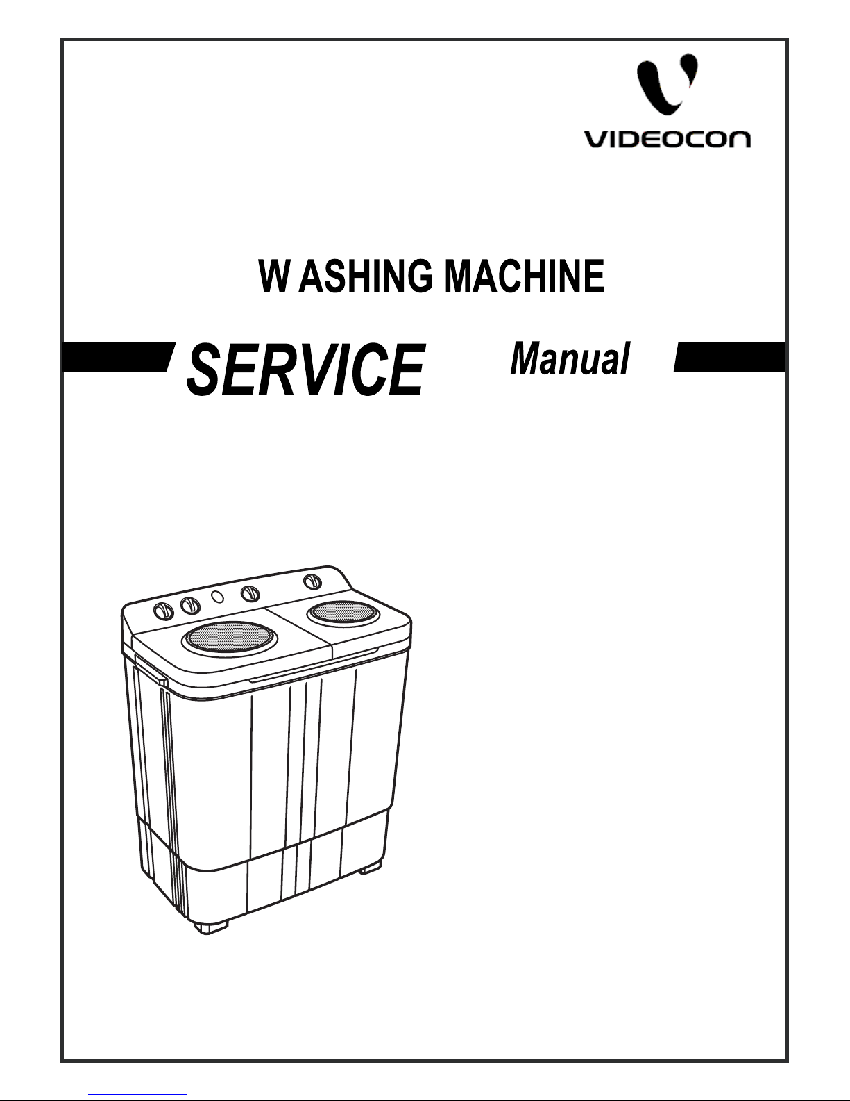
Model : Shine
(WM VSH60LMC,
WM VSH60PMC,
WM VSH60EMC,
WM VSH60AMC)
Model : Star
(WM VST60LMW)
Page 2
CONTENTS
1. SPECIFICATION________________________________________2
2. PRECAUTION__________________________________________3
3. CAUTIONS FOR SAFETY_________________________________4
4. INSTALLATION INSTRUCTIONS___________________________7
5. OPERATING INSTRUCTIONS_____________________________9
5-1 IDENTIFICATION OF PARTS___________________________9
5-2 CONTROL PANEL INFORMATION_______________________10
5-3 CARE AND MAINTENANCE____________________________11
6. SERVICE INFORMATION________________________________12
6-1 WIRING DIAGRAM___________________________________12
6-2 DISASSEMBLY INFORMATION_________________________13
6-3 TROUBLESHOOTING_________________________________20
6-4 CHECK POINT AFTER REPAIR_________________________22
7. EXPLODED VIEW_______________________________________23
8. BILL OF MATERIAL______________________________________29
SAFETY PRECAUTION !
DISASSEMBLE POWER CORD BEFORE SERVICING
RECONNECT ALL GROUNDING DEVICES
1
This service information is intended for individuals
possessing adequate background of electrical,
electronic and mechanical experience.
Any attempt to repair this appliance may result in
personal injury or property damage.
The manufacturer or seller cannot be responsible
for the interpretation of this information, nor can it
assume any liability in connection with its use.
IMPORTANT SAFETY NOTICE !
Page 3
1. SPECIFICATIONS
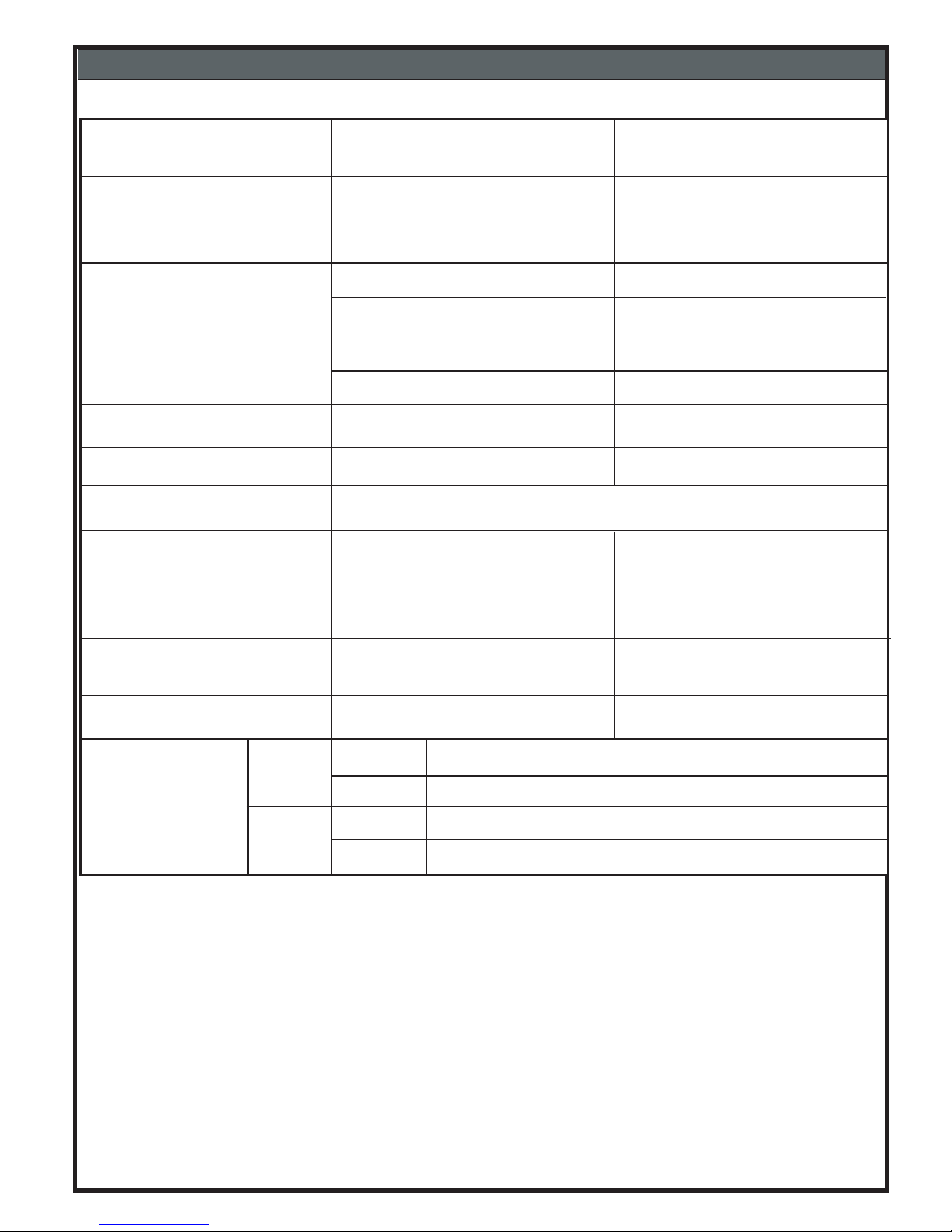
240V, 50 Hz AC
6.0 Kg
Max. 60 Liters*
Min. 30 Liters
Wash : 340 Watts
Spin : 180 Watts
Washing Capacity
Water Level
Rated Power
Consumption
Power Supply
Weight of the Machine
Machine Dimensions
Washing Method
22.5 kg
Length 750 mm x Width 435 mm x Height 890 mm
MODEL :
Shine
As per Standard Testing Condition.
* Max. Water level at over flow level.
Wash Time
Spin Time
Ampere
AC220V/50Hz
NO
LOAD
LOAD
WASH 1.2 ~ 1.6
SPIN 0.5 ~ 0.7
WASH 1.4 ~ 2.0
SPIN 0.7 ~ 1.3
Spinning Drum speed
1350 ~ 1400 rpm
2
Star
240V, 50 Hz AC
6.0 Kg
Max. 60 Liters*
Min. 30 Liters
Wash : 340 Watts
Spin : 180 Watts
22.5 kg
1350 ~ 1400 rpm
Multie Pulsator
20Min. Soak +
15Min Wash
05 Min.
Multie Pulsator
15Min Wash
05 Min.
Cascade
Yes No
Page 4

When performing troubleshooting and part replacement during servicing, note the following safety
precautions:
1-1.Safety Precautions
1-1-1.Use Genuine Parts
The components of the washing machine have safety features such as non-combustibility and voltage
withstanding.Therefore, always use the same part as suggested by the maker. In particular, be sure to use
only design rated parts in case of major safety parts identified by the marker.
1-1-2.Grounding
Connect the grounding wire to the shell plate, and bury it under at least 25 cm of earth : alternatively, connect
the ground wire to the appropriate pin on a properly grounded power receptacle. Never connect the wire to a
telephone line, lightning rod, or gas pipe.
1-2.Servicing Precautions
1-2-1.Observe Warnings
Be sure to follow special warning and precautions that are described on part labels and in the owner's manual.
1-2-2.Parts Assembly and Wiring
Be sure to use insulation material (such as tube and tape). And be sure to restore all parts and wires to their
original position. Take special care to avoid contact with sharp edges.
1-2-3.Perform Safety Checks after Servicing
After servicing, check to see that the screws, parts, and wiring are restored to their original positions, and
check the insulation between the external metals and the socket plug. In addition, place the washing machine
in a level position (less than1 (one) degree) to prevent vibration and noise during operations.
1-2-4.Insulation Checks
Pull out the plug from the power receptacle, pour water into the spin tub, and then set the timer. Check to see
that the resistance insulation between the terminals of the plug and the externally exposed metal is greater
than1M Ohm .
Note
:When it is impossible to perform insulation check with a 500V insulation resistance tester, use other
testers for inspection.
3
2. PRECAUTION
Page 5
Please observe the following notes for safety.
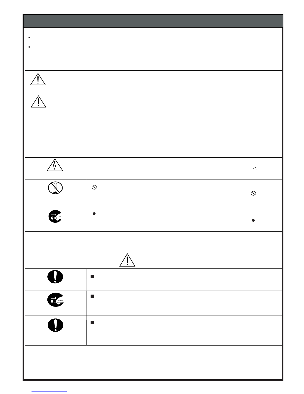
The symbols indicate as follows.
Symbol
Meaning
WARNING
CAUTION
Indicates possibility of death or serious injury of a repair technician and a
person near by through them is conducted work, or of a user by a defect of the
product after the work performed by the technician.
Indicates possibility of injury or physical damages* of are pair technician and a
person nearby through the misconducted work,or of a user by a defect of the
product after the work performed by the technician.
*Means secondary damages of property, furniture,domestic animal andpet.
GraphicSymbol
Meaning
ELECTRIC SHOCK
1.
indicates a caution(including a warning).
Specific instruction is followed bya graphic or characters in or near .
Symbol left warns an electric shock.
indicates prohibition (act must not be conducted).
Specific instruction is followedby a graphic or characters in or near .
Symbol left warns not to disassemble.
DO NOT
DISASSEMBLE
UNPLUG
indicates forcing (act must be conducted).
Specific instruction is followed bya graphic or characters in or near .
Symbol left warns to unplug the power cord.
WARNING
OUTOFCHILD
Advise the customer to keep children out of the work place.
Children may be injured with a tool or a disassembled part.
Unplug power cord for the work such as disassembling which is not
unnecessary to power on
.Do not hold the
plug by awethand.
Failing to unplug may cause an electric shock.
UNPLUGPOWER
USE
REPAIR PARTS
Use the specified repair parts when repairing the product.
Otherwise, a malfunction may occur.
Also,a short circuit, ignition or other danger to the customer may occur.
3. CAUTIONS FOR SAFETY
4
Page 6
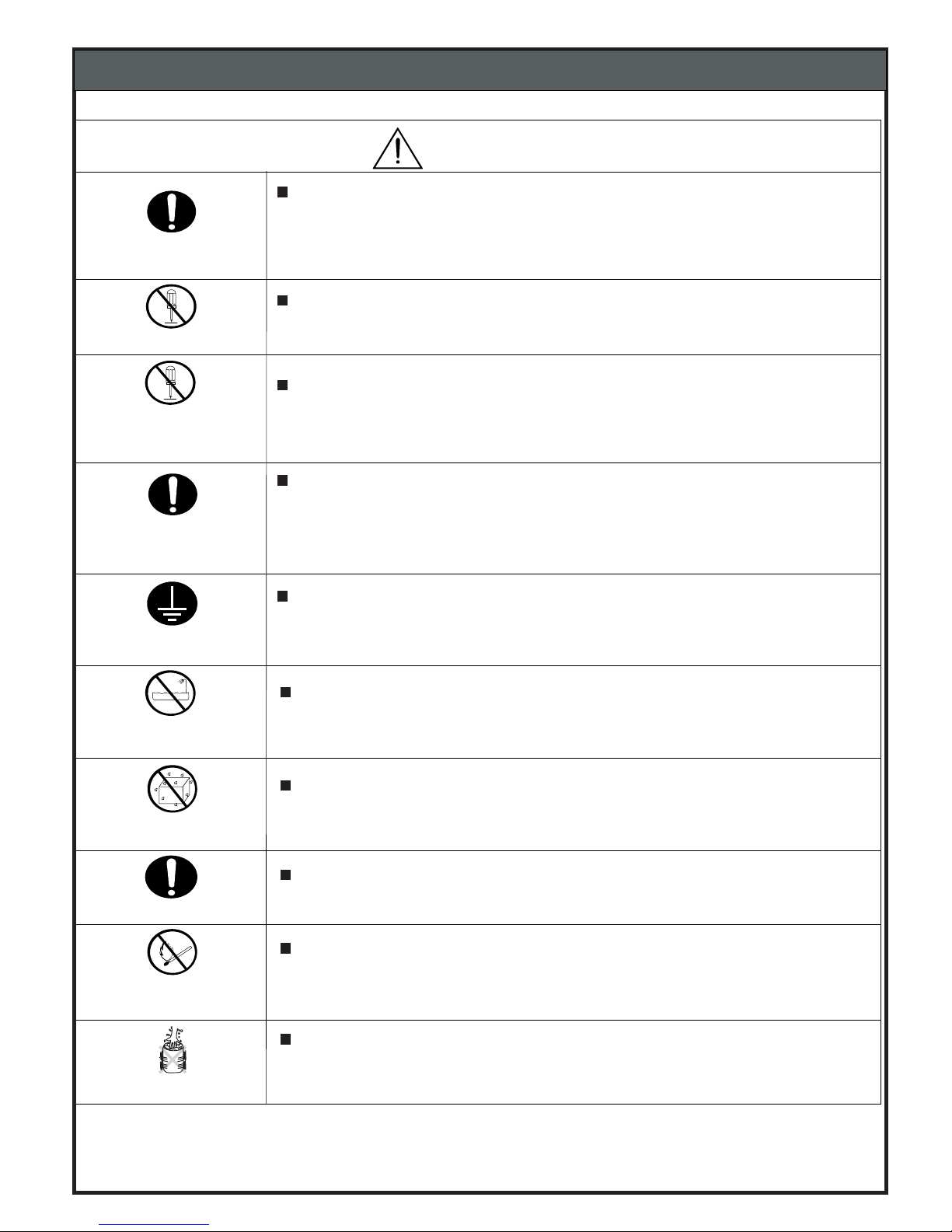
WARNING
After repair, measure insulation resistance between the charging part
(power cord plug) and the non-charging metallic part (ground) with an
insulation resistance meter(500V).The resistance shall be10M Ohm or more.
Failing to check the insulation resistance may cause a short circuit, electric
shock or other diseases to the customer.
DO NOTMODIFY
Do not modify the product.
An electric shock or ignition may occur.
Only are pair technician can disassemble and repair.
An electric shock, ignition or malfunction may cause injury.
USEEXCLUSIVE
SOCKET
Use an exclusive 220VAC/15Asocket for the washing machine.
Otherwise, an electric shock or ignition may cause. Sharing the same socket
with other instrument causes heating of a branch socket and result in a fire.
CONNECT
GROUNDINGWIRE
Connect the grounding wire.
Failing to do so may cause an electric shock when a short circuit occurs.
Consult an electric workshop or a sales shop.
Do not install in a bathroom or a placeexposed to windor rain.
An electric shock or a short circuit may cause a fire.
DO NOTSPLASH
WATER
Do not pour or immerseelectrical parts into water or liquid solution.
An electric shock or ignition may occur.
Wipe off dust adhered to the plugof power cord.
Dust may cause a fire.
AVOID
INFLAMMABLE
Do not put inflammable into the washing tub.
Do not put cloths stained withkerosene,gasoline,benzene,thinner,alcohol,
etc.lt may cause a fire or explosion.
Do not touch the laundry before the spin basket stops completely.
The laundry entangles your hand causing an injury even if the basket rotates
slowly. Pay special attention to children.
DO NOT
DISASSEMBLEAND
REPAIR
CHECKINSULA-
TIONRESISTANCE
DONOTUSEWET
PLACE
REMOVEDUST
DO NOTTOUCH
3. CAUTIONS FOR SAFETY
5
Page 7
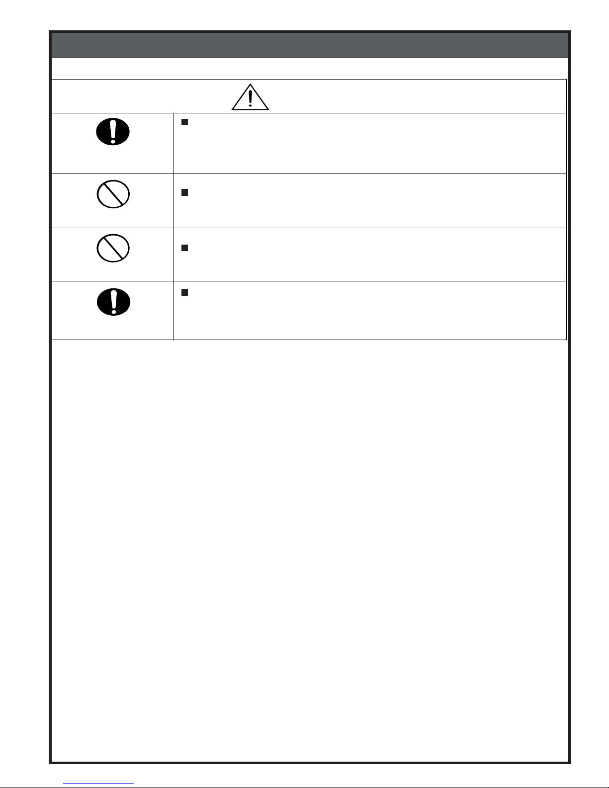
CAUTION
INSTALL
CAREFULLY
Ask an service enginer to install the product.
Install the product securely and safely according to the electrical equipment
technical standard and the wiring standard.
Incorrect work causes an electric shock and a fire.
Do not pull the power cordwhen unplugging.
Hold the power plug to unplug.
An electric shock or short circuit may cause a fire.
DANGERHAND
Do not insert your hand under thewashing machine during operation.
There is a rotary part under the machine which may cause an injury.
WATERLEAKAGE
Before starting washing, open the faucet and check water supply hose joint
which shall not be loosened for no water leaks.
The loose screw or hose joint may cause water leakage resulting in an
unexpected damage.
DO NOTPULL
3.CAUTIONS FOR SAFETY
6
Page 8
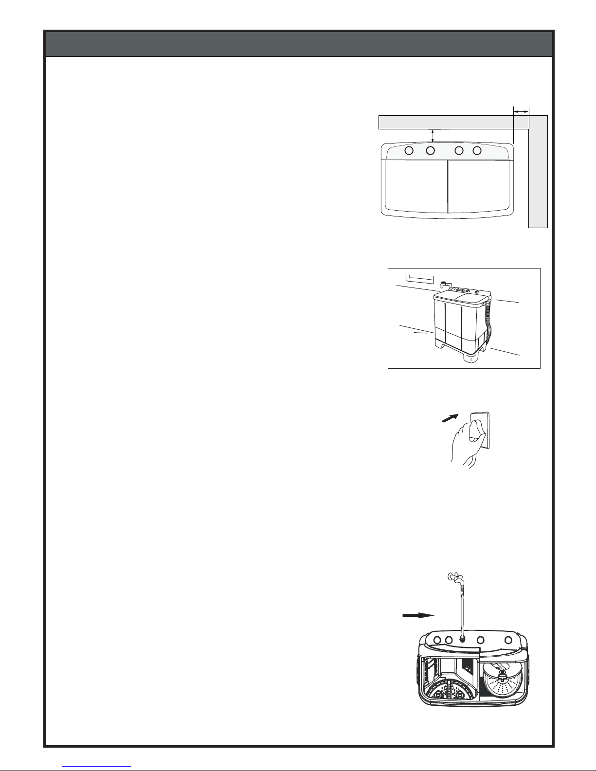
4-1.Installation
4-1.Level Specifications and Wall-Clearance Distances
1) Instal the washing machine on a solid and level floor.
3) Place the machine at least 15cm away from the wall.
2) Place menton an inclined, weak or rough floor may
cause abnormal noise or trembling.
4. INSTALLATION INSTRUCTION
15cm
15cm
4-2. Install the Washing Machine in well ventilated area.
Machine and Power socket should be covered from top
to avoid rain, sunlight or water on machine.
4-3. Insert the Power plug firmly into the main power supply.
4-4.Connect the Water supply hose to Tap and Inlet pipe
in Panel.
7
Page 9
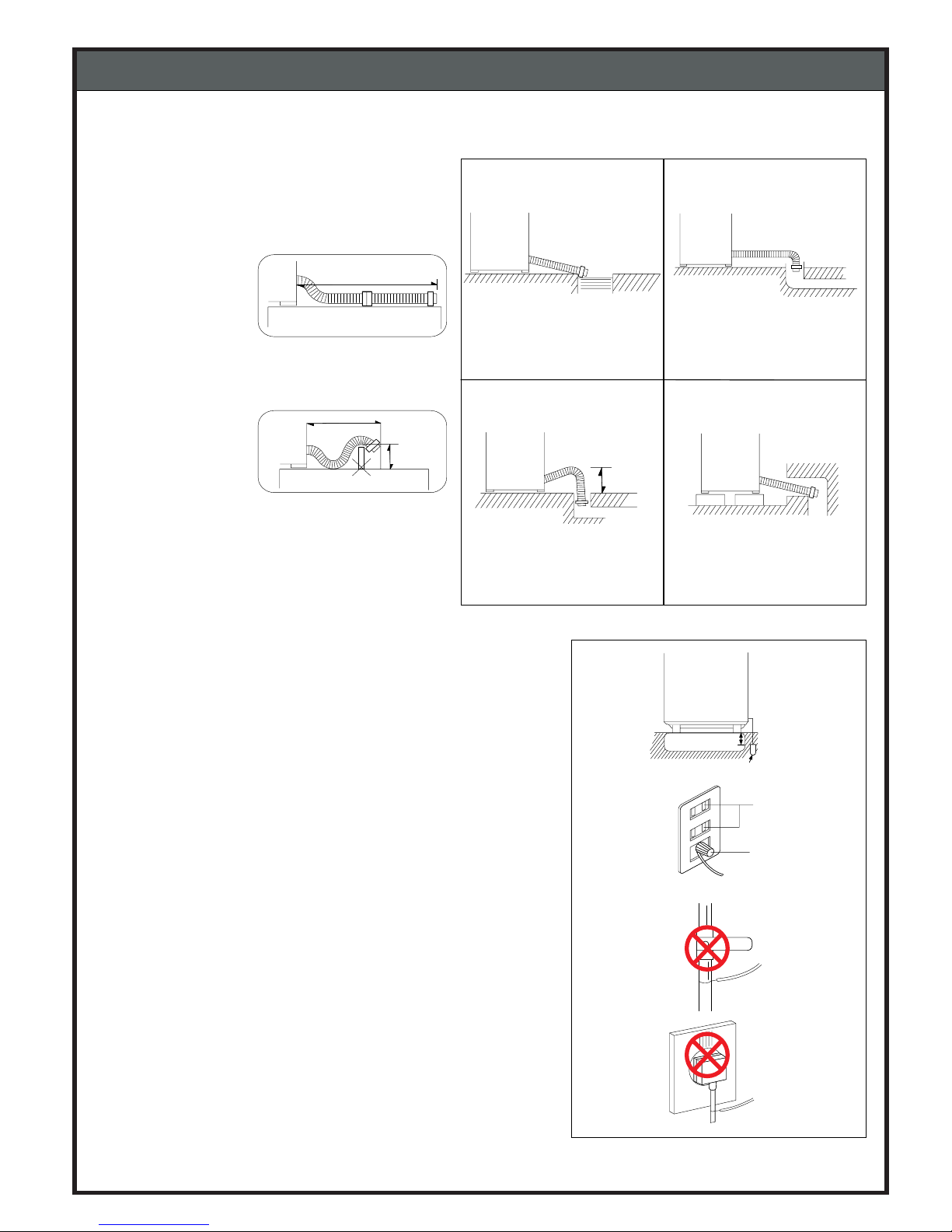
4-5. Positioning the Drain Hose
1)When there is no threshold, the length of the
drain hose should not exceed 3m.
2)When it is necessary to connect the drain hose
with the drain outlet far away, connect the
extension hose and
applicable parts
available from
dealers or service
centers.
3)
Do not install the drain hose where it must exceed
over a threshold of 3 cm or more; do not install
where there is a
threshold
and the hose
must exceed for
more than 2m.
4-6. Grounding
1) Upon installing grounding, make sure if power socket is out
of power outlet.
2) Grounding should be connected to either metal water supply
pipe or coppergrounding pole deeper than 25cmin the damp
ground.(Fig1)
3) If water pipe is a plastic, no protection is obtained from
a possible electric shock.
4)If the power outlet is available with grounding connection,
grounding in the washing machine should be firmly connected to
the connection of the outlet.(Fig2)
5)You should not connect, the grounding to the gas-pipe because
it will cause an explosion. (Fig3)
6)If the grounding is connected to either telecommunication line
or lightning-arrest line, an extreme hazard is caused therefore,
no connection should be made to such lines.(Fig4)
Do not put the end of the
drain hose into the water.
Do not place the hose upto
the floor of the drain outlet.
When the drain hose must
be positionedat a high
place, install
the washing
machine to a higherplace
Do not make the midpart of
the hose than the ends
positioned higher.
3m
2m
3 cm
GROUNDING
WIRE
GROUNDING POST
DEEPER
THAN 20cm
(FIG 1)
GROUNDING WIRE
GAS PIPE
(FIG 3)
GROUNDING WIRE
(FIG 4)
(FIG 2)
OUT LET
GROUNDING
TERMINAL
GROUND WIRE
4. INSTALLATION INSTRUCTION
8
Page 10
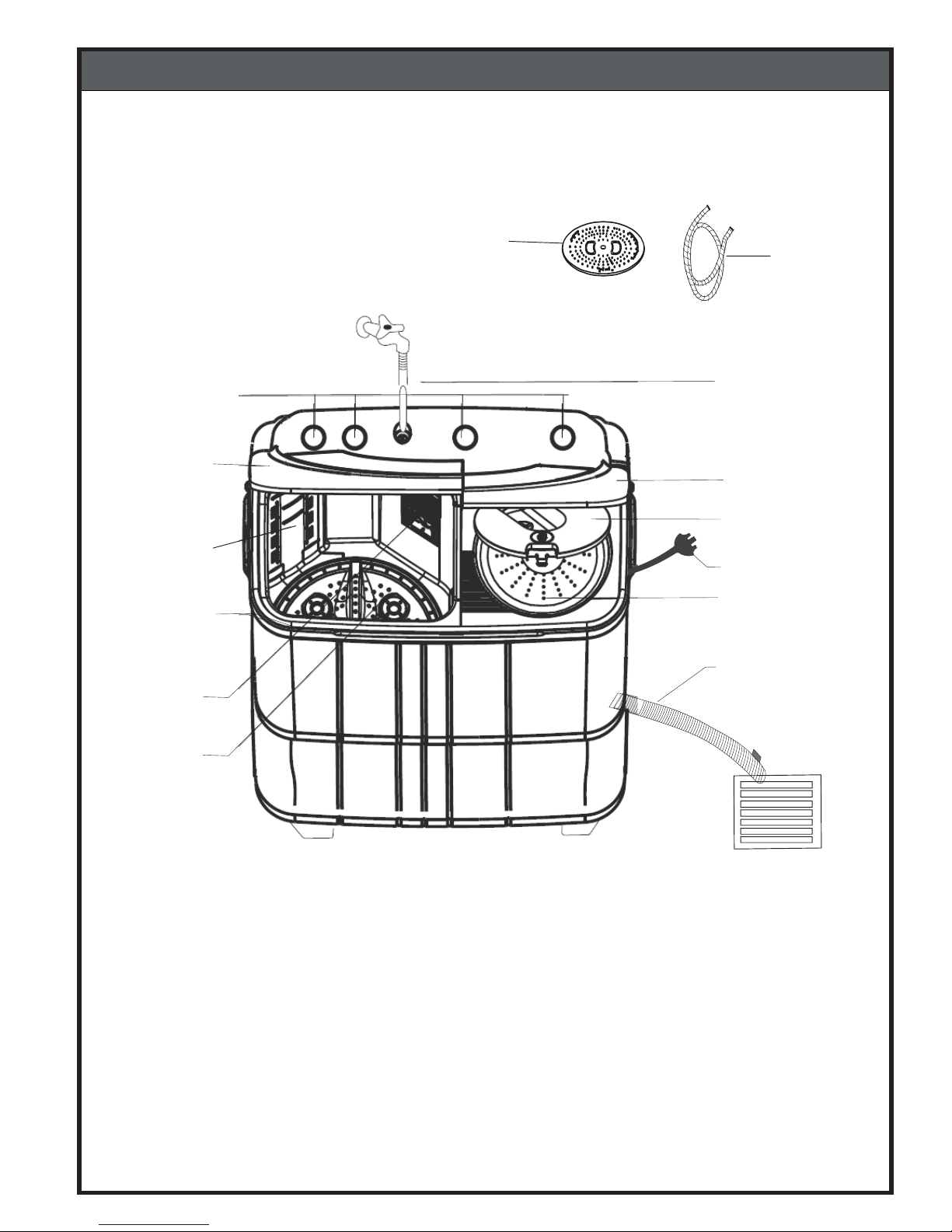
5-1. IDENTIFICATION OF PARTS
5. OPERATING INSTRUCTION
Control Panel
Inlet Hose
Water Selector
Wash Tub
Lid
Wash Tub
Overflow filter
Pulsator
Spinning Cap
(Please do not match this figure with your machine as it may be different from your model.
These are schematic diagrams only).
9
Knobs
Cascade*
(*Cascade is not applicable for Aqua Model)
Power Cord
Drain Hose
Spinner Lid
Inner Lid
Spinner Tub
Page 11
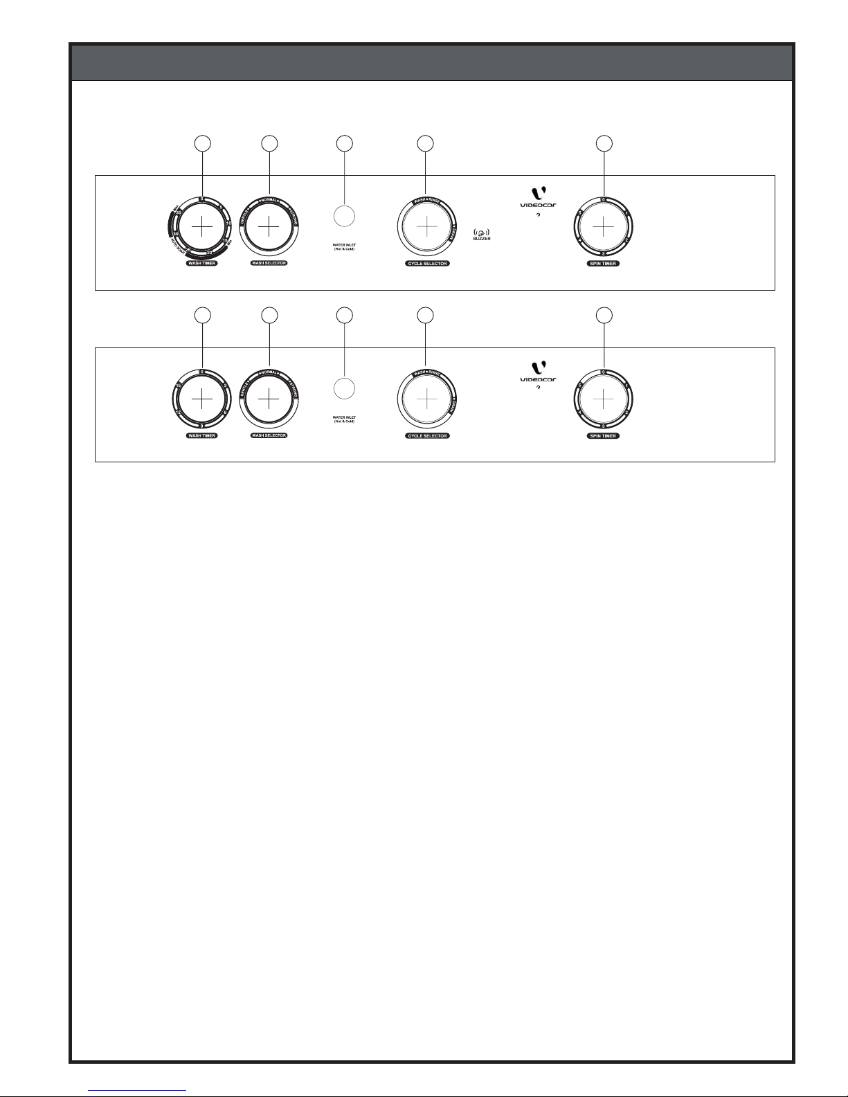
5-2. CONTROL PANEL INFORMATION
5. OPERATING INSTRUCTION
1. Water Inlet : This is used to direct water supply to wash tub for washing or spin tub for spin shower.
2. Wash Timer : This timer is used for Auto SOAK, WASH and RINSE operations.
Following combination can be selected.
A) Auto Soak + Wash :- Select the desire soak time by setting the
Timer between 15 ~ 35 min., (”SOAK” not available in model “AQUA”)
B) Wash/Rinse :- You can select any Wash/Rinse time up to 15min. if
you want Wash/Rinse time for shorter duration turn the knob up to
10min. position and then turn it back to desired position.
3. Wash Selector : Set the knob to ‘STRONG’, ‘GENTLE’, ‘NORMAL’ according to kinds and
quantity of the laundry.
4. Cycle Selector : This selector is to set for “WASH/RINSE” or “DRAIN” the water from wash tub.
- WASH / RINSE for wash & rinse program.
- DRAIN for draining the water from the wash tub.
5. Spin Timer : This timer is used to select your desired length of time to spin laundry by
using 5 minutes timer. (if you want to set the timer to 2 min. or less, turn the
selector up to the 5 min. position, and then turn it back to the desired position.
Note : Do not rotate the knobs more then prescribed limits.
10
SHINE 6.0 kg
STAR 6.0 kg
Wash
Ec
1
2
3
4
5
Wash
Ec
1
2
3
4
5
Page 12
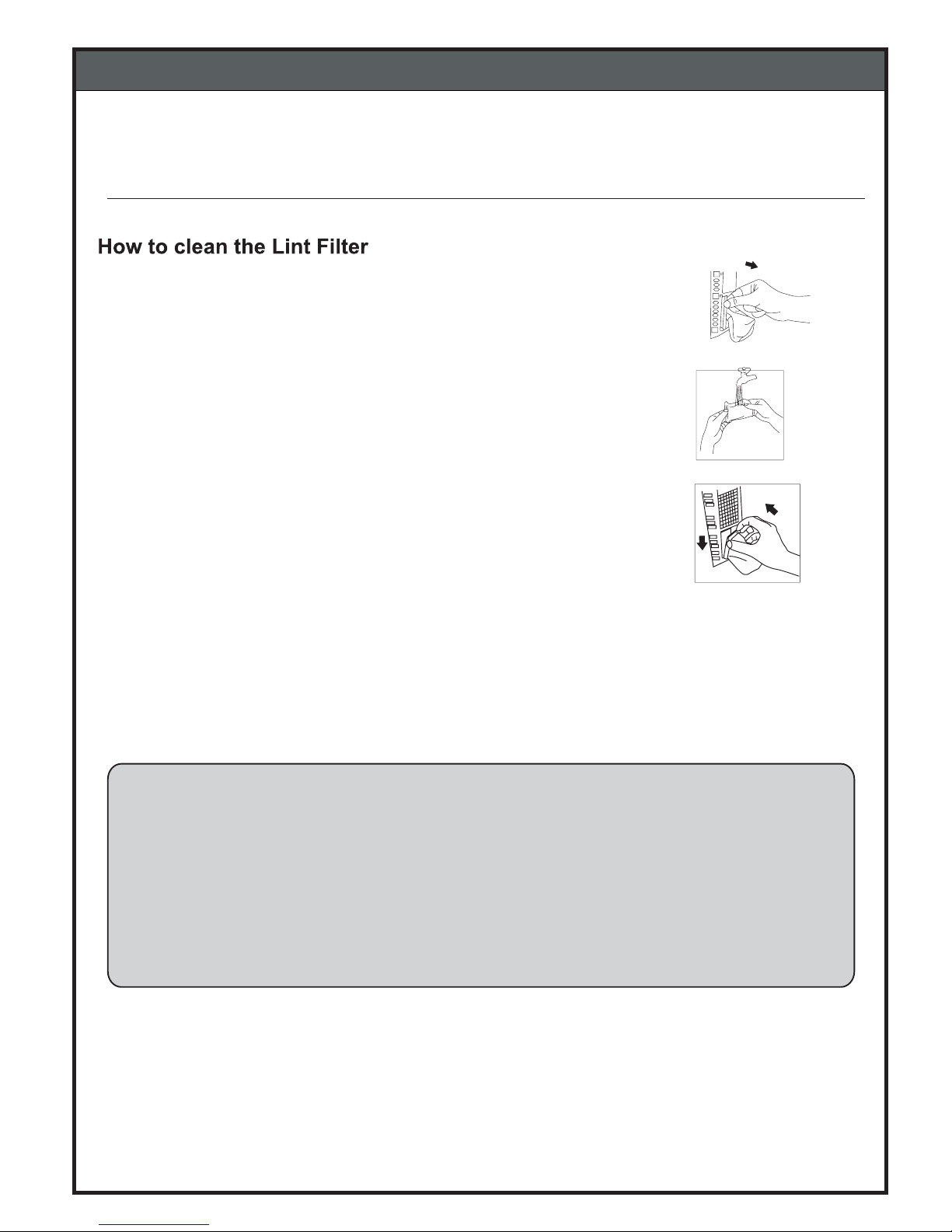
5. OPERATING INSTRUCTION
5-3. CARE AND MAINTENANCE
1. Pull out the lint filter from the lock, use fingers to press
and pull out at the part of the lint filter’s side
Cleaning the Wash Tub
BE SURE TO REMOVE THE POWER PLUG FROM MAIN POWER SUPPLY BEFORE CLEANING THE MACHINE.
2. Rinse the dirt from filter with clean water.
3. Set back to the original position. Insert the bottom first
as shown, press filter down and lock the upper lock as shown.
1. After washing is complete, fill fresh water above the level of Pulsator,
without adding clothes.
2. Run the machine for 1 ~ 2 minutes and then turn the Cycle Selector knob
position when Pulsator is still rotating.to “DRAIN”
3. When water is completely drained out, turn the Cycle Selector knob
position.to “WASH/RINSE”
4. Finally turn OFF the machine.
11
Page 13
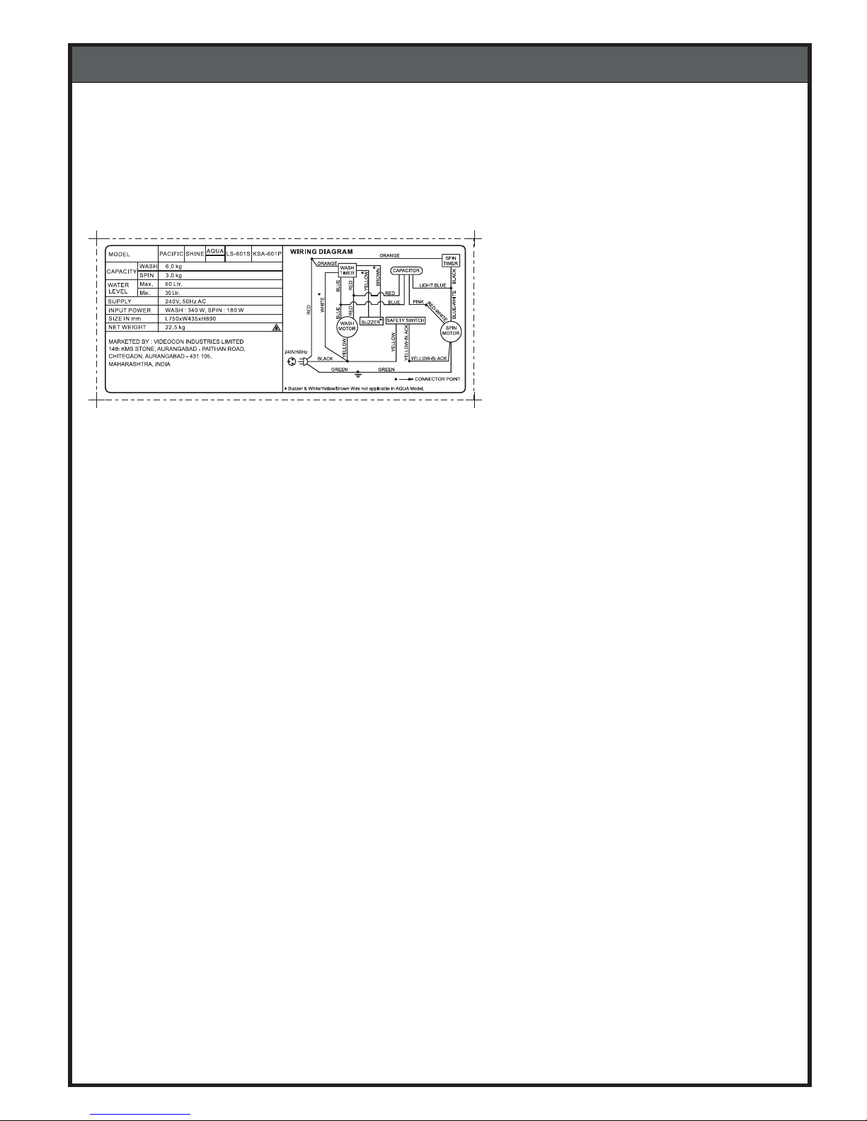
SHINE/STAR
6. SERVICE INFORMATION
6-1. WIRING DIAGRAM
12
STAR
Page 14
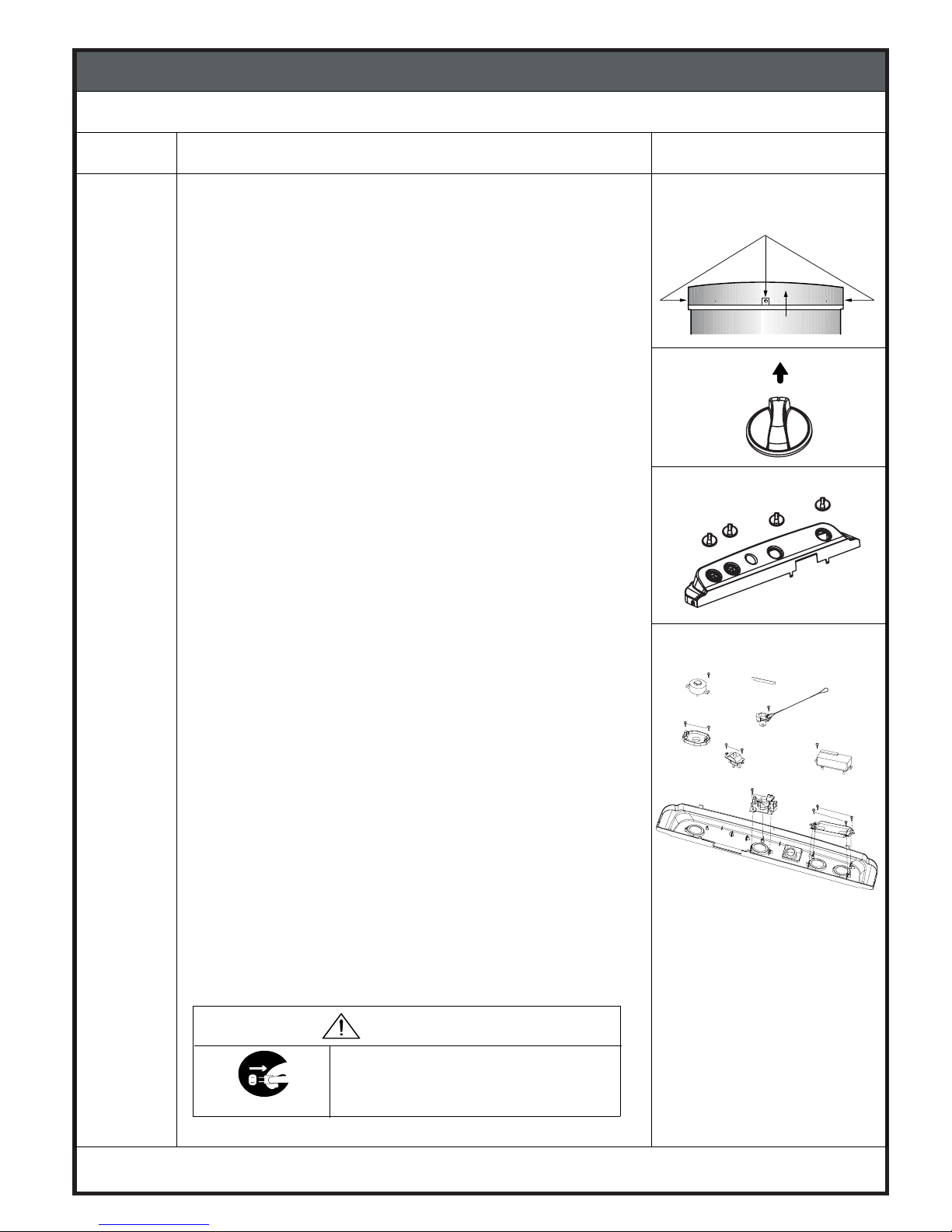
6. SERVICE INFORMATION
ITEM HOW TO DISASSEMBLE AND ASSEMBLE DIAGRAM
WASH TIMER
AND
SPIN TIMER
1) Disassembly of the WASH TIMER.
Using screw driver unscrew the scre ws from the
Panel and Tub. (Fig 1)
Lift up Panel while Pulling to theFront. (Fig 3 )
CAUTION
:Please do not apply an excessive force.
Disassemble the COCK ROD - A that is connectedto the
LEVER- A DRAIN by screw
Disassemble Knob assembled to the WASH TIMER &
SPIN TIMER, WASH SELECT OR AND CYCLE SELECTOR.
(Fig 3)
(Fig 4)
WARNING
Unplug the power cord for the work
unnecessary to power on like disassembling.
Do not hold the plug by a wet hand.
Failing to unplug may cause an electric
shock.
UNPLUG POWER
(Fig 1)
SCREW
PANEL
(Fig 2)
13
6-2. DISASSEMBLY INFORMATION
1.
2.
(Fig. 2)
3.
6.
Remove the Wash, Spin & Drain holder asm from Panel by
4.
unscrewing the screws from Panel and holder.
Remove the Wash, Spin timer from Holder by unscrewing
5.
the screws from Wash, Spin timer and holder.
Remove the Buzzer from Panel by unscrewing
7.
the screws from Buzzer and Panel.
Remove the Flat Spring from Lever A Drain
8.
(Fig 4)
SCREW
COCK ROD A
LEVER A DRAIN
SCREW
WASH TIMER
SPIN TIMER
SPIN HOLDER
DRAIN HOLDER
WASH HOLDER
WASH HOLDER
FLAT SPRINGFLAT SPRING
BUZZER
Page 15
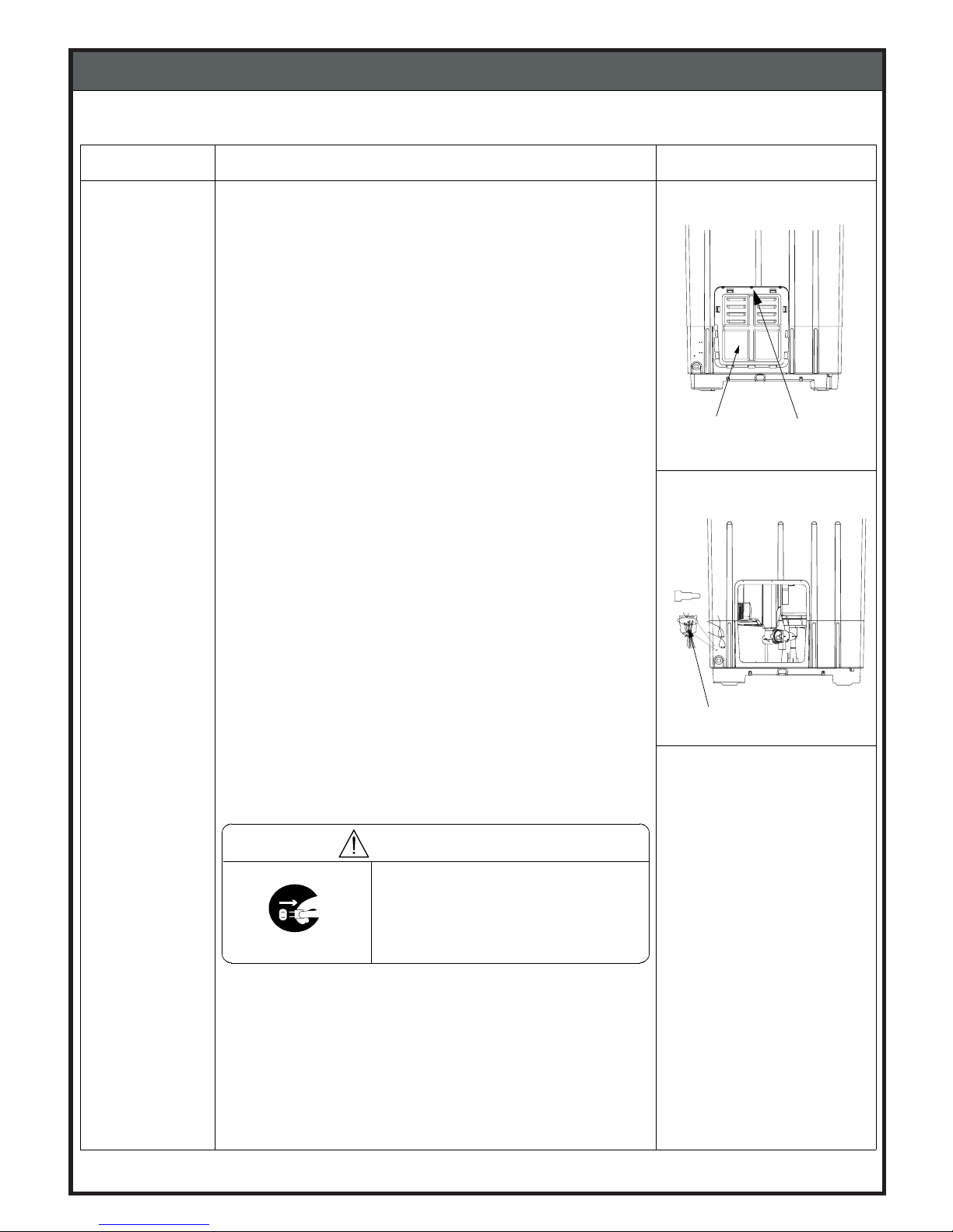
Item How to Disassemble and Assemble Drawings
Untighten the screws from BACK COVER andTUB,
and disassemble it by removing the Snap Locks.(Fig 1 )
Remove a plastic bag on Connector part, and
cut off all wire.(Fig2)
WARNING
UNPLUG POWER
Unplug the power cord for the
work unnecessary to power on like
disassembling. Do not hold the
plug by a wet hand
Failing to unplug may cause an
electric shock.
PLASTIC BAG
(Fig 1)
COVER-BACK
SCREW
6. SERVICE INFORMATION
(Fig 2)
14
6-2. DISASSEMBLY INFORMATION
BACK
COVER
1.
2.
Page 16
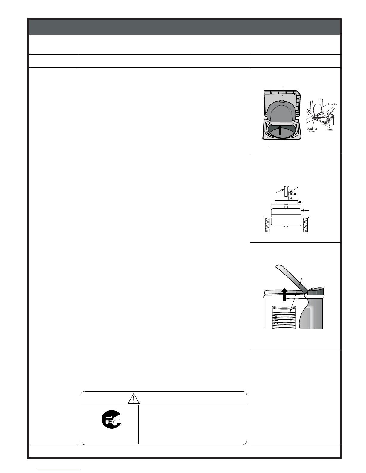
Item How to Disassemble and Assemble Drawings
BASKET-
SPINNING
OUTER TUB COVER is fitted to BODY B with snap locks.
To remove OUTER TUB COVER, hold it tightly from
center and PULL upwards.
Snap locks will disengage from the BODY B.
Untighten a nut assembled to the BRAKE WHEEL, and turn
a bolt to counterclockwise and removeit.(Fig. 2)
(Used tool boxdriver)
Lift the SPIN BASKETto upward and remove it,
from BRAKE WHEEL. (Fig 3 )
CAUTION: Beware not to loose the WATER-CUTTER
because it will slide out from SHAFT-Bwhen
BASKET-SPINNING is removed.
Besure to followings after replacing the SPIN BASKET.
Screw properly theboltwhich holds BRAKE WHEEL to
SPIN BASKET,otherwise, too high fastening maycause
breaking the bolt.
After screw the bolt,youmust tighten the nut
for secure fixing.
Unplug the power cord for the
work unnecessary to power on like
disassembling. Do not hold the
plug by a wet hand
Failing to unplug may cause an
electric shock.
UNPLUG POWER
WARNING
(Fig. 3)
SPIN LID
(Fig 1)
SPIN TUB
NUT
BOLT
(Fig 2)
SPIN
MOTOR
BRAKE WHEEL
PULL
SPIN
TUB
6. SERVICE INFORMATION
INSERT
15
6-2. DISASSEMBLY INFORMATION
1.
OUTER TUB COVER
(Fig. 1)
2.
3.
Page 17
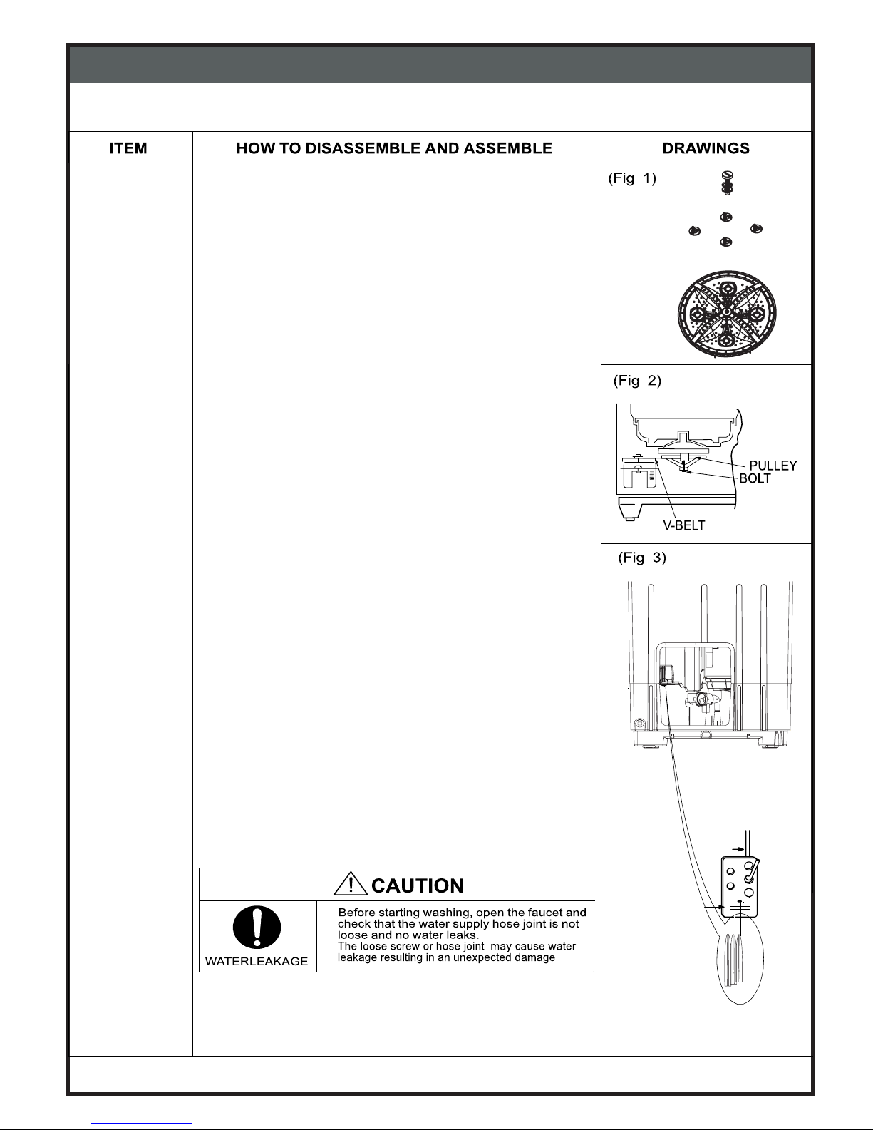
6. SERVICE INFORMATION
16
6-2. DISASSEMBLY INFORMATION
Unscrew the Pulsator Asm, using ‘+ ve’ screw driver. (Fig. 1)
1.
3.
Remove V BELT from Bearing Case Pulley and Motor Pulley.
(Fig. 2)
TUB SLOT
4.
Keeping the SPIN LID at open position,
remove the ACTUATING LEVER form the
PULSATOR
V-BELT
FLEXIBLE WIRE
FLEXIBLE WIRE
ACTUATING LEVER
FLEXIBLE WIRE PLATE (Fig 3)
5.
Remove flexible wire plate from tub slot.
PLATE
PULSATOR
PULSATOR SCREW
ROTOR
Page 18
6. SERVICE INFORMATION
17
ITEM HOW TO DISASSEMBLE AND ASSEMBLE DRAWINGS
7.
(Fig 5)
(Fig 6)
(Fig 7)
NUT
BOLT
SHAFT-B
COUPLING
MOTOR
SPIN MOTOR
and
WASH MOTOR
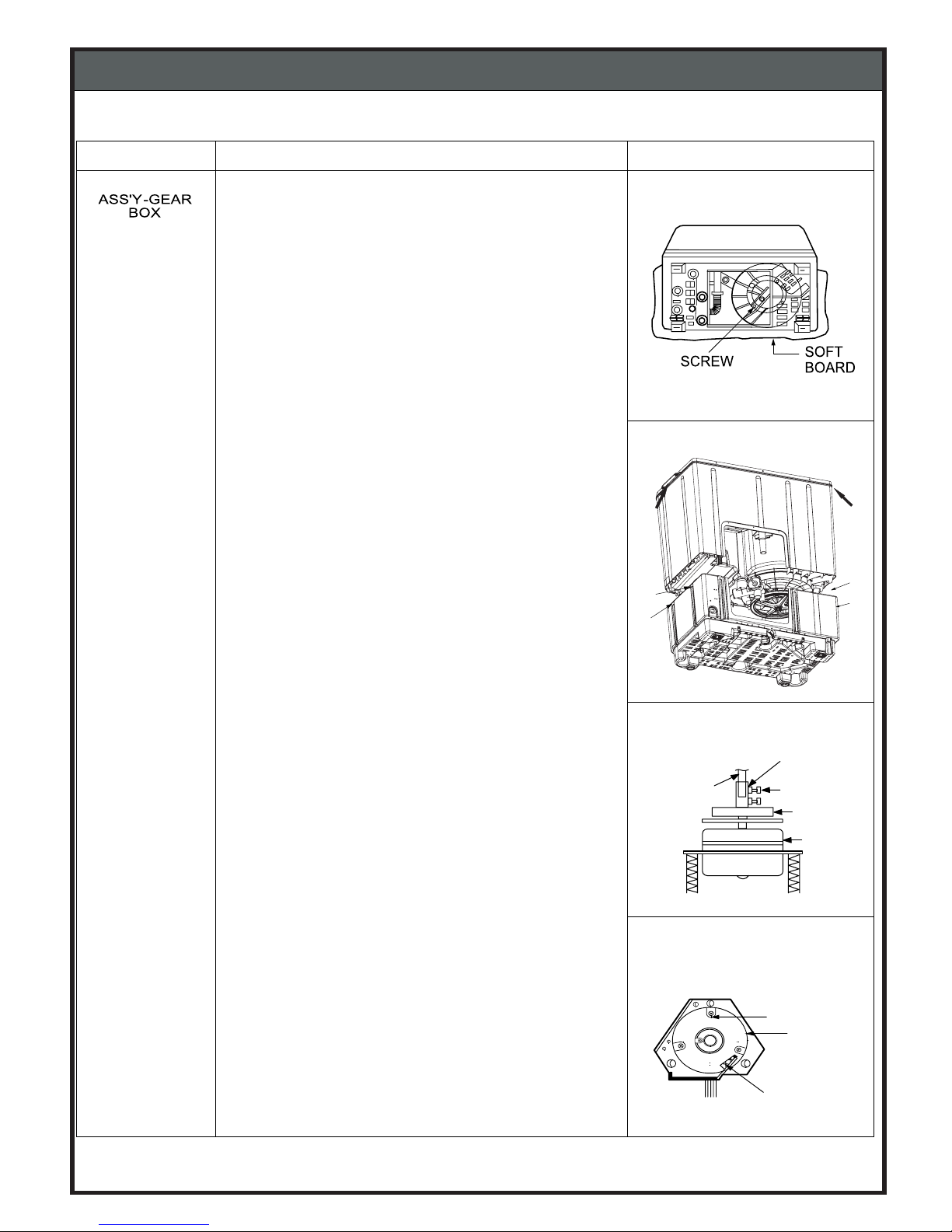
Unscrew the screws from Base and Tub for all four sides.
(Fig. 6)
Screws
Screws
Lift the Tub upside holding from Handles and separate
Tub from Base (Fig. 6)
Handle
Handle
8.
6.
Lay down the machine of soft board placed on floor,
to avoid scratch or damage on machine. (Fig. 5)
turn a bolt to counterclockwise and removeit.(Fig. 7)
(Used tool boxdriver)
9.
Untighten a nut assembledto the BRAKE WHEEL,and
SCREW
FRAMEBRAKE
SPRING
Using driver,disassemble three Brake frame
screws. (Fig 8)
10.
(Fig 8)
6-2. DISASSEMBLY INFORMATION
Page 19
ITEM HOW TO DISASSEMBLE AND ASSEMBLE DRAWINGS
11.
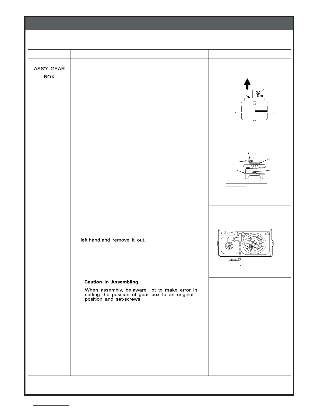
Untighten Brake Asm Nut and Bolt. Pull the Brake Asm
upside and remove it from Spin Motor shaft.
Remove the Brake Frame.(Fig9)
12.
Lift the Spin Motor from Base.
11) Disassembly of WASH MOTOR.
1.
Unsrew the Motor Pulley Nut and Bolt.
Lift the Motor Pulley from the Wash Motor Shaft.
2.
Unscrew threeset screwsassembled to the Wash
Motor and Base.(Fig 10)
3.
Lift the Wash Motor from Base.(Fig. 10)
(Fig 9 )
(Fig 10)
PULL
NUT
BOLT
COUPLING
BOLT
MOTORWASHING
NUT
SCREW
PULLEYMOTOR
(Fig 11)
6. SERVICE INFORMATION
18
6-2. DISASSEMBLY INFORMATION
SPIN MOTOR
and
WASH MOTOR
12.Separate the Gear Box asm by unscrewing
the screw from Gear Box asm and Tub.
n
Move Gear Box asm two or three times right
Page 20
ITEM HOW TO DISASSEMBLE AND ASSEMBLE DRAWINGS
FILTER UNIT
ASSEMBLY
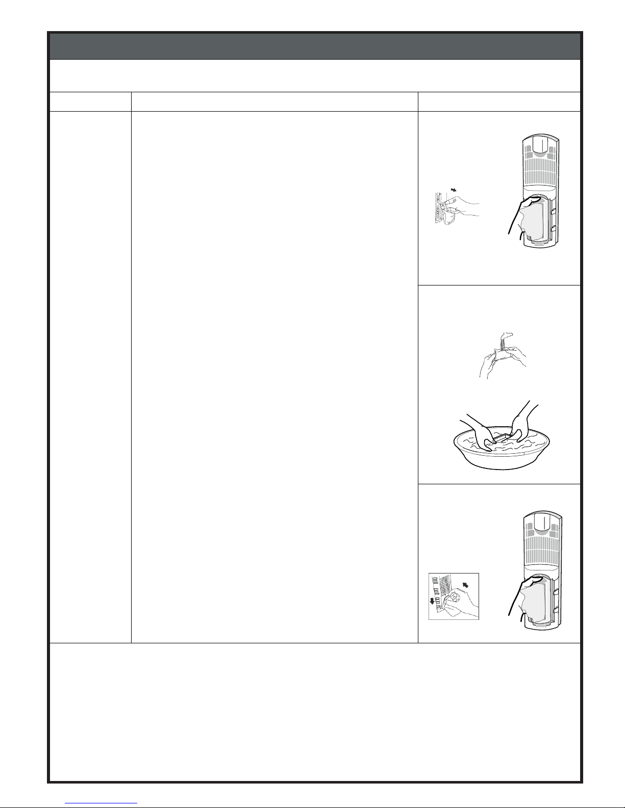
1.
Pull out the filter unit from over flow filter lock, use
3.
Set back to the original position, inset the bottom
(Fig 1)
(Fig 2)
(Fig 3)
6. SERVICE INFORMATION
19
Over Flow Filter with Filter Unit
use fingers to press and pull out (Fig 1)
first as shown press down and lock as the arrow (Fig 3)
2.
Turn lint filter inside out, and rinse the dirt from filter.
(Fig 2)
6-2. DISASSEMBLY INFORMATION
Page 21
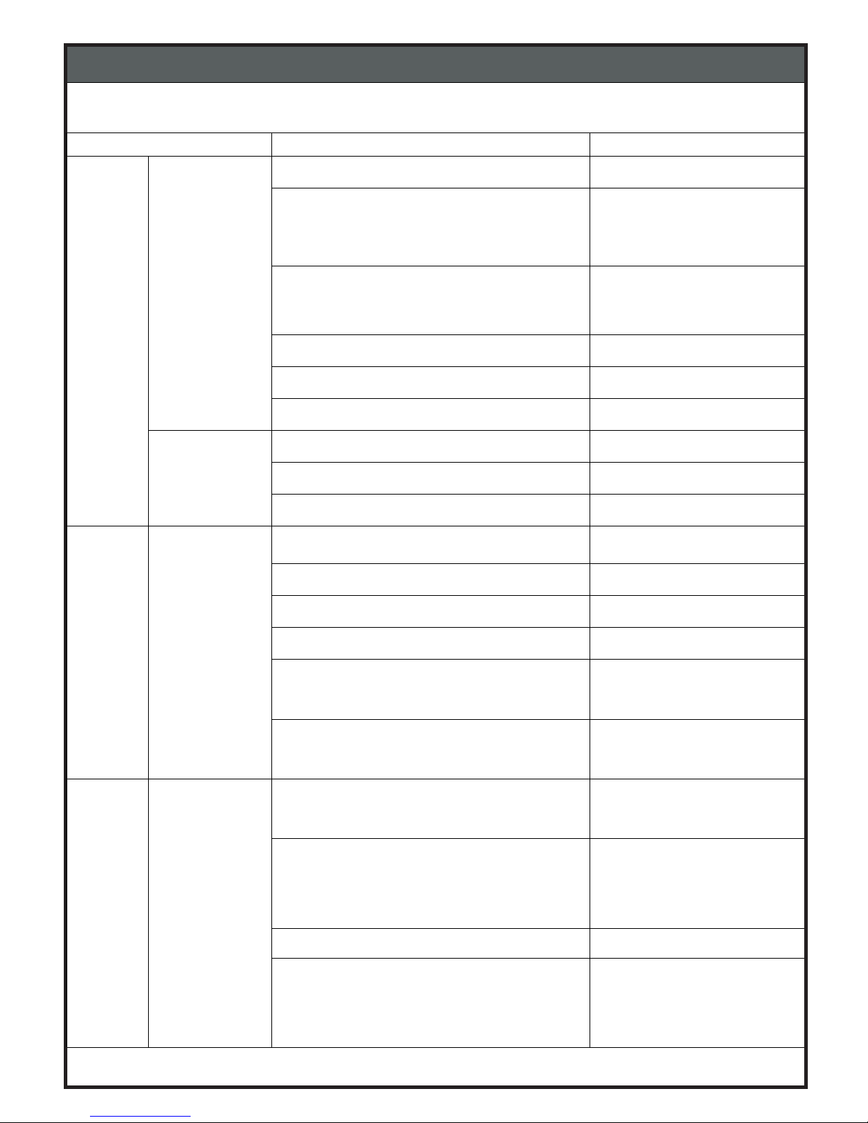
TYPICAL FAILURE POSSIBLE CAUSE REPAIR
Wash
Rinse
No agitation or
poor agitation
Power plug is not connected properly Insert power plug correctly
Defective Motor
Defective Timer
Defective Gear-Box
Replace
Clothes or objects bit in pulsator gap Remove pulsator and check.
Remove objects
Defective mounting of pulsator screw Fixing pulsator
Belt loose Adjust the belt tention
Too large amout of wash load Take out some clothes
Excessive
noise during
agitation
Coin or button between pulsator andtub Remove objects
Defective Bearing Case Replace Bearing Case
Defective fixing of pulley or transformed Adjust pulley or replace it
Drain No Drain
Drainning does
not stop
Drain Hose is not lowered
Make sure to lower drain
hose
Lints accumulated in Drain Hose Clean or replace Hose
Cock Rod A is broken or seperated Replace or connet
Defective DV Bellow Adjust or replace
D.V-Spring is broken away or elesticity is
insufficient
Adjust or replace D.V-spring
Guide-A.T is derailed or defective Guide-A.T
Adjust or replace
Spin No spinning Lid is open Close the lid adn advise
customer
Out of adjustment of Safety Switch or
defective Safety Switch.
Adjust fixing positon of
Safety Switch or replace
Safety Switch
Defective Spin imer Replace
Brake wire is broken.
Replace B r a k e w i r e
6. SERVICE INFORMATION
6-3. TROUBLE SHOOTING
20
Page 22
6. SERVICE INFORMATION
6-3. TROUBLE SHOOTING
TYPICAL FAILURE POSSIBLE CAUSE REPAI R
Spinning
basket does
not stop
Brake shoe is worn off or broken Replace brake shoe
Brake arm does not move Replace brake frame
Brake spring is broken away or elesticity is
insufficient
Replace brake Spring
Excessive
noise during
spin
Machine is not level.
Weak floor.
Level the machine.
Install on a horizontal
and stable floor
Screw for fixing motor come loose. Fix screw
Clothes breake into the gap between Tub and
Basket
Remove clothes
21
Page 23
After repairing, be sure to make the following trial operation to see if the washer operates normally.
CheckPoint Inspection & Judgement
1) Insulation resistance Unplug thecord from the power outletand turn on all the timers.Then
measure the insulation resistance between the plug (both of 2pins) and
grounding wire of the machine.
The measured value should be more than1M
Ohm
In the following case, check sufficiently.
1)Replace the electrical parts with new ones.
2)Used in a moistplace.
3)Used more than 5years.
2) Safety device Check the full stoptimeof the spin basket.
Braking time should be as follows.
3) Safety designated parts Replace withthe designated parts inthecase the used parts are not proper.
(Refer to'*"marked parts inthe parts list)
4) Wiring Check tosee ifthe lead wireisproperly connected without looseness or
overtension and taping and setting arefirmlyperformed.
5) Screwsand Nuts Check toseeifthe screws,nuts, etc are firmly tightened and the screw
locks are applied.
6) Removal ofuseless
matter
Check toseeifuseless matters (Screws,bits ofwire, etc) are left inside
7)Lekage ofoiland water Check toseeifoilorwater leaks out around bellow-spinning, gear box,
motors and connection ofd.v-case.
8) Power-cord Check toseeifthe cord, theplug, the outlet etc, are not damaged. Do not
use table tape with multi-wiring.
9) Level Installation Check tosee ifthe machine installed horizontally.
Load
Normalstoptime
Noload
Ratedload
Witin7sec.
Within10sec.
6. SERVICE INFORMATION
6-4. CHECK POINT AFTER REPAIR
the machine.
22
Page 24
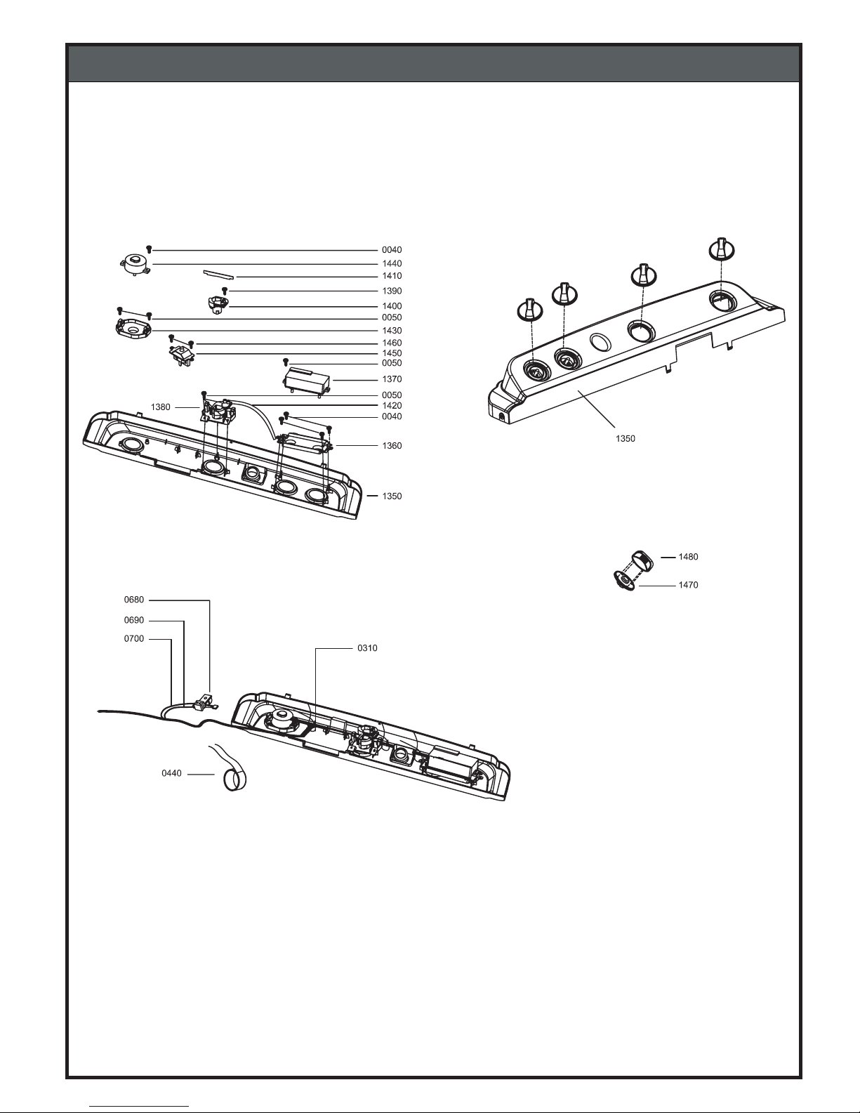
7. EXPLODED VIEW
7-1. PANEL ASSEMBLY
23
Page 25
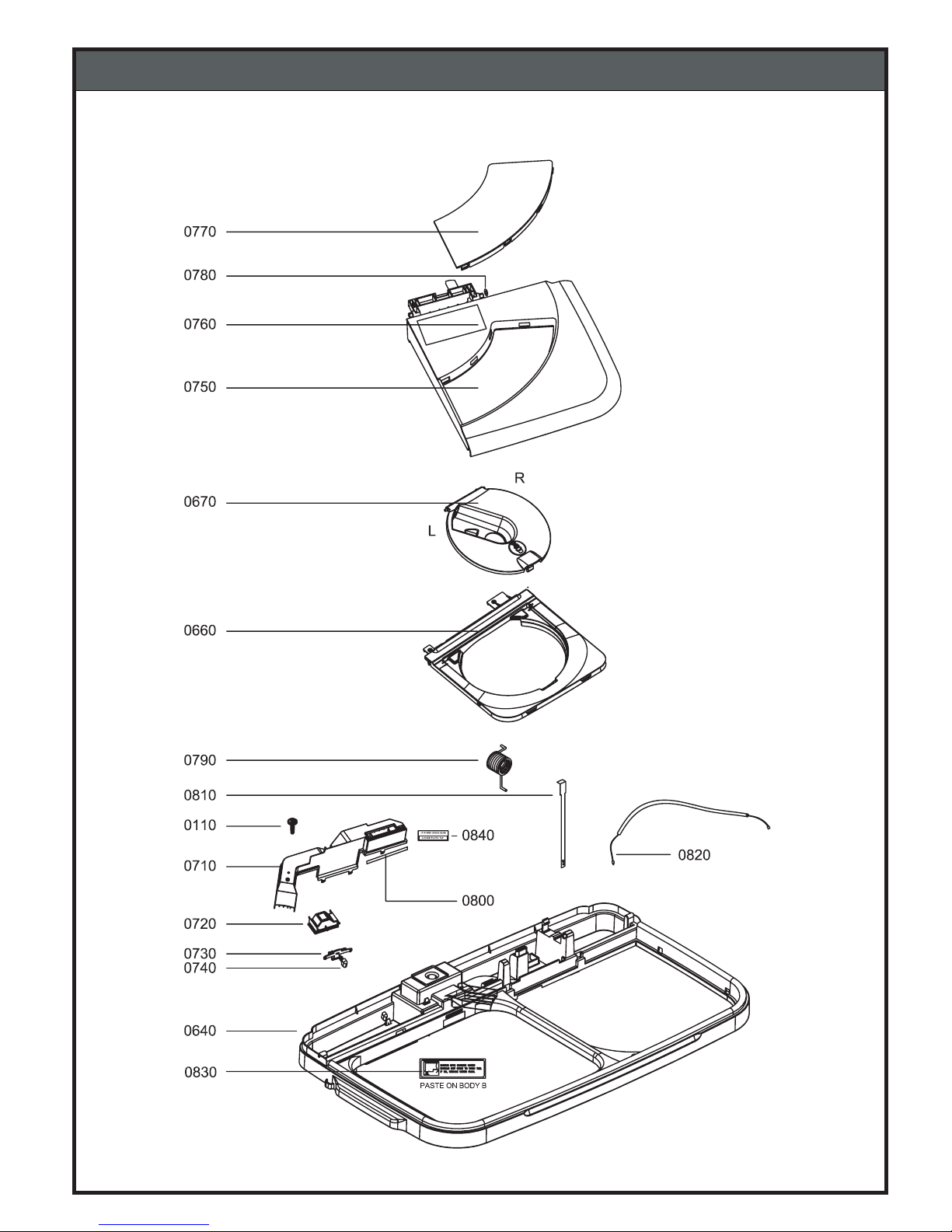
7. EXPLODED VIEW
7-2. BODY - B ASSEMBLY
24
Page 26
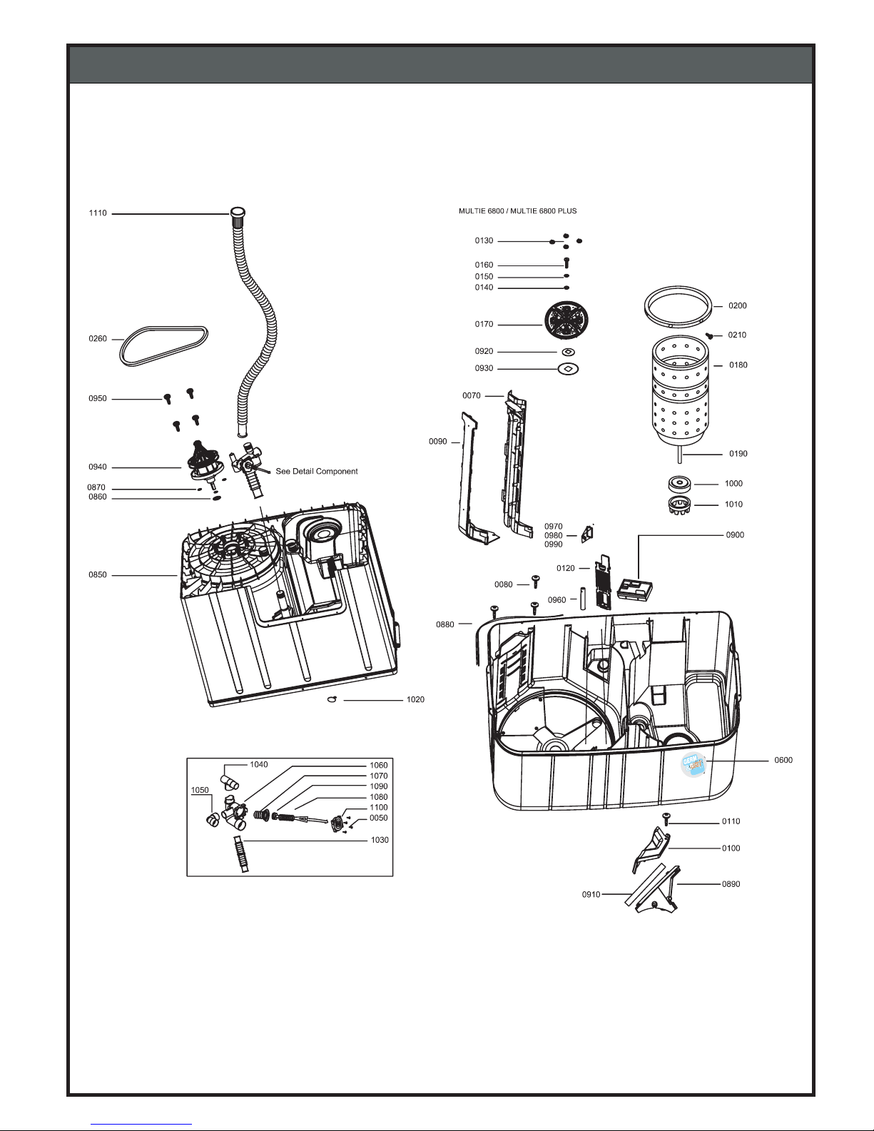
7. EXPLODED VIEW
7-3. TUB ASSEMBLY
25
FREE
Page 27
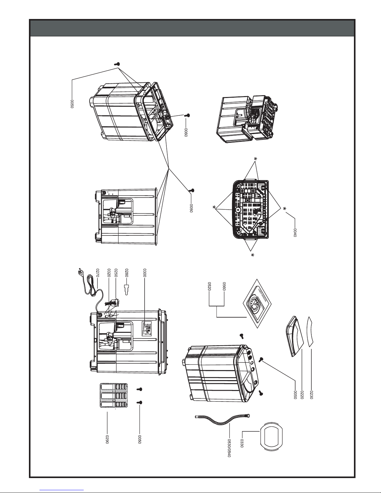
7. EXPLODED VIEW
7-4. TUB ASSEMBLY
26
Page 28
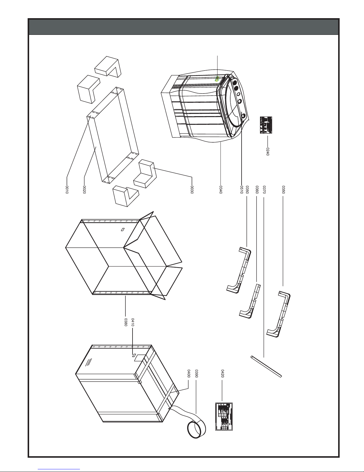
7. EXPLODED VIEW
7-5. TUB ASSEMBLY
27
0600
Page 29
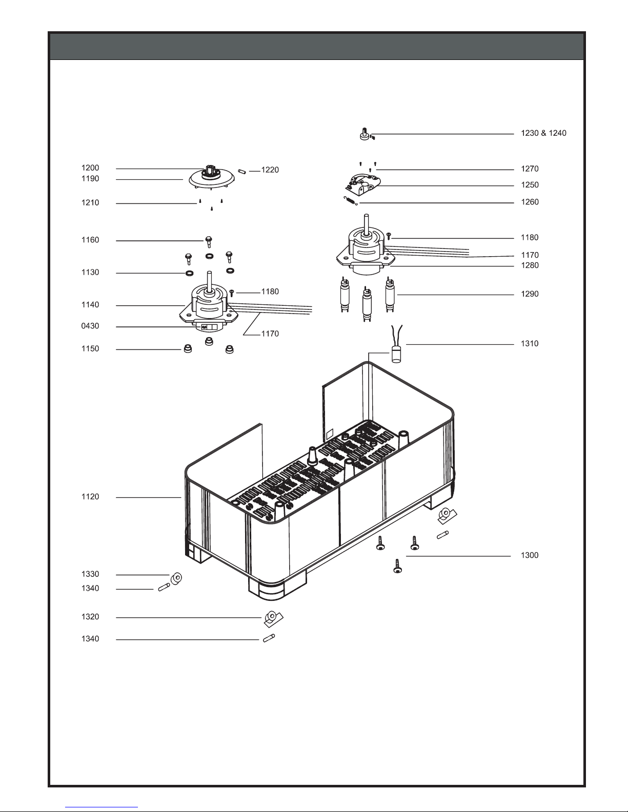
7. EXPLODED VIEW
7-6. BASE ASSEMBLY
28
Page 30
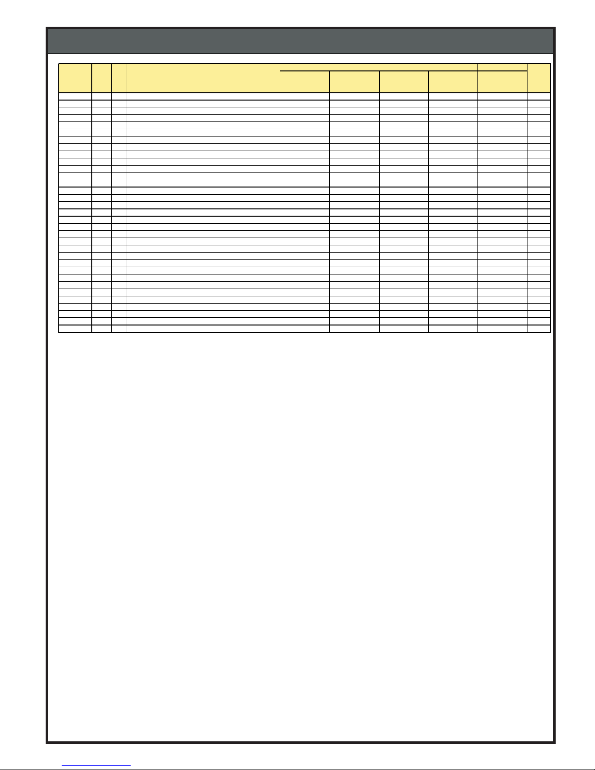
BILL OF MATERIAL
29
STAR
WM VSH60LMCSFU
WM VSH60PMCSFU
WM VSH60EMCSFU
WM VSH60AMCSFU
WM VST60LMWSFU
0010 0.005 KG STAPLE PIN,12 X 25 1100000970 1100000970 1100000970 1100000970 1100000970
0020 1 PC SHEET,CORRUGATED,5PLY,770X455X105MM 1300004598 1300004598 1300004598 1300004598 1300004598 Y
0030 1 PC BUFFER,THERMOCOL,BOTTOM,MULTIE 6000 1300004599 1300004599 1300004599 1300004599 1300004599
0040 9 PC SCREW ,BIND,TAPPING,M4X14.5,6800 1100005281 1100005281 1100005281 1100005281 1100005281
0050 25 PC SCREW ,SPECIAL,TAPPING,XTB4+12C 1100000922 1100000922 1100000922 1100000922 1100000922
0060 1 PC SCREW ,SPECIAL,TAPPING,436,SA43/63 1100005288 1100005288 1100005288 1100005288 1100005288
0070 2 PC CASCADE,FRONT,MULTIE 6000,LIGHT GREY 1200032315 1200024025 1200024204 1200024193 1200032315 Y
0080 6 PC SCREW ,MS,BIND TAPPING,12BU,MULTIE 6000 1100028848 1100028848 1100028848 1100028848 1100028848
0090 2 PC CASCADE,BACK,MULTIE 6000,APPLIANCES GREY 1200019611 1200019611 1200019611 1200019611 NR Y
0100 1 PC CAP,CASCADE,MULTIE 6000,LIGHT GREY 1200032297 1200024026 1200024205 1200024194 1200032297 Y
0110 2 PC SCREW ,SPECIAL,TAPPING,405,FA55/61/71 1100000909 1100000909 1100000909 1100000909 1100000909
0120 1 PC FILTER,OVERFLOW,MULTIE 6000,LIGHT GREY 1200032298 1200024027 1200024206 1200024195 1200032298
0130 4 PC ROT OR,WITH TAB,MULTIE 6800,VG GREY 1100043833 1100031520 1100031552 1100031551 1100043833 Y
0160 1 PC UNIT,SCREW 673,O RING,WASHER 651,6800 1100040694 1100040694 1100040694 1100040694 1100040694
0170 1 PC PULSATOR,MULTIE 6000,LIGHT GREY 1200032299 1200024016 1200024016 1200024016 1200032299 Y
0180 1 PC TUB,SPIN,MULT IE 6000,LIGHT GREY 1200032300 1200032300 1200032300 1200032300 1200032300 Y
0190 1 PC COUPLING A,CRCA,ROUND,SA 63,MULTIE 6800 1100000621 1100000621 1100000621 1100000621 1100000621
0200 1 PC BALANCER,SINGLE,MULTIE 6000,LIGHT GREY 1200032301 1200032301 1200032301 1200032301 1200032301 Y
0210 4 PC SCREW ,BIND,TAPPING,10BU 1100006700 1100006700 1100006700 1100006700 1100006700
0220 1 PC LID,W ASH,LS 63,LIGHT GREY 1200032317 1200035278 1200035278 1200035278 1200032317 Y
0230 1 PC INSERT,WASH LID,KSA-601P,TRANSPARENT GRE 1200027704 1200035276 1200035276 1200035276 1200027704 Y
0240 1 PC SHEET,INST RUCTION,MULTIE 6800/SA63 1100021350 1100021350 1100021350 1100021350 1100021350
0250 0.001 KG BAG,POLYETHYLENE,CONNECTOR,MULTIE 6800 1100005202 1100005202 1100005202 1100005202 1100005202
0260 1 PC V BELT,L688MM,MULT IE 6000 1100029807 1100029807 1100029807 1100029807 1100029807 Y
0270 1 PC MAINS CORD,5A/250V,MULTIE 6800 1100006692 1100006692 1100006692 1100006692 1100006692 Y
0280 8 PC CONNECTOR A,COMMON 1100000618 1100000618 1100000618 1100000618 1100000618
0290 1 PC COVER,BACK,LS-601S/KSA-601P,VG GREY 1200027652 1200027652 1200027652 1200027652 1200027652 Y
0300 1 PC STICKER,W IRING DIAGRAM,GRAN,SA,COMMON 1100054837 1100054837 1100054837 1100054837 1100054837
0310 4 PC HOLDER,LEAD W IRE,1.4X90 MM,COMMON 1100006687 1100006687 1100006687 1100006687 1100006687
0320 2 PC HOLDER,LEAD W IRE,1.4X170 MM,COMMON 1100000705 1100000705 1100000705 1100000705 1100000705
0330 1 PC BUFFER,THERMOCOL,SPIN TUB,MULTIE 6000 1300004587 1300004587 1300004587 1300004587 1300004587
0340 0.034 KG BAG,POLYETHYLENE,785X450X25MIC 1300004596 1300004596 1300004596 1300004596 1300004596
0350 1 PC BUFFER,THERMOCOL,TOP,LS 63 1300004585 1300004585 1300004585 1300004585 1300004585
SBOM
SHINE
Exploded
view code
Qty Unit Object description
Page 31
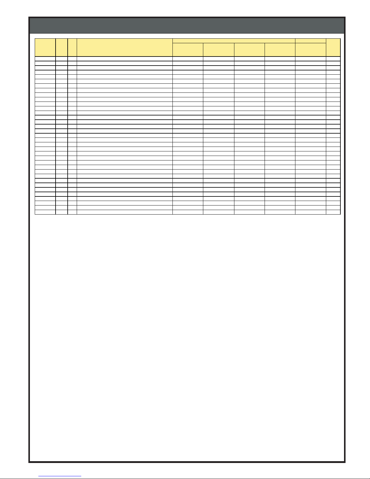
BILL OF MATERIAL
30
STAR
WM VSH60LMCSFU
WM VSH60PMCSFU
WM VSH60EMCSFU
WM VSH60AMCSFU
WM VST60LMWSFU
0360 1 PC BUFFER,THERMOCOL,BENCHMARK,MULTIE6000 1300004586 1300004586 1300004586 1300004586 1300004586
0370 1 PC SHEET,CORRUGATED,3PLY,715X250MM 1300004595 1300004595 1300004595 1300004595 1300004595
0380 1 PC BOX,PACKING,3PLY,PRINTED,N,LOGO,AQ,PA 1300007800 1300007800 1300007800 1300007800 1300007800
0390 0.04 PC TAPE,BOPP,60MMX65M,TRANSPARENT 1300000867 1300000867 1300000867 1300000867 1300000867
0400 6.5 M STRAP,POLY PROPYLENE,BOX,COMMON 1300001430 1300001430 1300001430 1300001430 1300001430
0440 0.019 PC TAPE,INSULAT ION,ISI MARK 1400000335 1400000335 1400000335 1400000335 1400000335
0480 0.011 KG ACRABOND,997,07 07,PURPLE COLOUR 1400002189 1400002189 1400002189 1400002189 1400002189
0490 0.002 KG GREASE, MULTIPURPOSE 1100012042 1100012042 1100012042 1100012042 1100012042
0510 0.13 M FOAM,1MMX1500MM,ROLL 1300000357 1300000357 1300000357 1300000357 1300000357
0520 1 PC CAP,SPIN,MULTIE 6000,VD W HITE 1200019597 1200019597 1200019597 1200019597 1200019597
0530 1 PC HOSE,W ATER,INLET,MULTIE 6000 1100029808 1100029808 1100029808 1100029808 1100029808
0540 1 PC FEED HOSE T IP WM 1100025442 1100025442 1100025442 1100025442 1100025442
0560 1 PC INSTRUCT ION MANUAL,SA,FAMILY,COMMON 1100049397 1100049397 1100049397 1100049397 1100049397
0590 1 PC STICKER,PVC,GERM & RUST ,FREE,SA COMMON 1100045167 1100045167 1100045167 1100045167 1100045167
0600 1 PC STICKER,VINYL,SERVICE,VID/KEL/KEN/EKL 1100054714 1100054714 1100054714 1100054714 1100054714
0610 0.03 KG EMA FILM,490MM 1300004594 1300004594 1300004594 1300004594 1300004594
0620 0.011 KG EMA FILM,185MM 1300004592 1300004592 1300004592 1300004592 1300004592
0630 0.007 KG EMA FILM,340MM 1300004593 1300004593 1300004593 1300004593 1300004593
0640 2 PC STICKER,PAPER,BARCODE,80MMX 150MM 1100033269 1100033269 1100033269 1100033269 1100033269
0650 2 PC STICKER,PAPER,COL.IND.ROUND,LIGHT GREY 1100048381 1100045222 1100045223 1100045224 1100048381
0660 1 PC HOSE,HOLDER B,MULT IE 6000 1100053121 1100053121 1100053121 1100053121 1100053121
0670 6 PC HOSE,HOLDER C,MULT IE 6000 1100053122 1100053122 1100053122 1100053122 1100053122
0680 1 PC FOAM,PU,195X8X2MM,PROT,FRONT,MULTIE 6000 1100041399 1100041399 1100041399 1100041399 1100041399
ASSY,BODY B,KLA60LMC,VG GREY 1200032294 1200035270 1200035269 1200035268 1200032294
0640 1 PC BODY B,KSA-601P,VG GREY 1200027703 1200028936 1200029109 1200029111 1200027703 Y
0660 1 PC COVER,TUB,OUTER,MULTIE 6000,LIGHT GREY 1200032309 1200024020 1200024020 1200024020 1200032309 Y
0670 1 PC LID,INNER,MULTIE 6000 1200019614 1200019614 1200019614 1200019614 1200019614 Y
0680 1 PC SW ITCH,SAFETY,MULTIE 6000 1100037101 1100037101 1100037101 1100037101 1100037101
0690 1 PC W IRE,PVC,YELLOW,CUTTING,1M 1100029809 1100029809 1100029809 1100029809 1100029809
0700 1 PC W IRE,PVE,YELLOW,BLACK,1M 1100029810 1100029810 1100029810 1100029810 1100029810
0710 1 PC NOZZLE,MULT IE 6000 1200019618 1200023374 1200023374 1200023374 1200019618 Y
0720 1 PC FUNNEL,MULTIE 6000 1200019619 1200019619 1200019619 1200019619 1200019619
0730 1 PC SLIDER,FUNNEL,MULTIE 6000 1200019620 1200019620 1200019620 1200019620 1200019620
0740 1 PC KNOB,SLIDER,MULTIE 6000,LIGHT GREY 1200032310 1200024021 1200024021 1200024021 1200032310
0750 1 PC LID,SPIN,LS 63,LIGHT GREY 1200032318 1200035277 1200035277 1200035277 1200032318 Y
Exploded
view code
Qty Unit Object description
SHINE
SBOM
Page 32
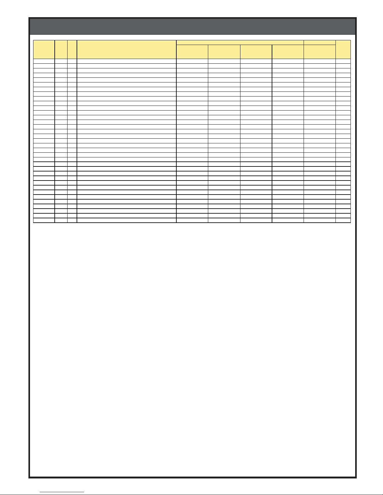
BILL OF MATERIAL
31
STAR
WM VSH60LMCSFU
WM VSH60PMCSFU
WM VSH60EMCSFU
WM VSH60AMCSFU
WM VST60LMWSFU
0760 1 PC STICKER,CAUTION,MULTIE 6800 1100005299 1100005299 1100005299 1100005299 1100005299
0770 1 PC INSERT,SPIN LID,KSA-601P,T RANSPARENT GRE 1200027705 1200035275 1200035275 1200035275 1200027705 Y
0780 1 PC W ASHER,SPIN LID,MULTIE 6000 1100029806 1100029806 1100029806 1100029806 1100029806
0790 1 PC SPRING,LID HINGE,6000 1100029789 1100029789 1100029789 1100029789 1100029789
0800 2 PC FOAM,PE,500X10X2,NOZZLE,MULTIE 6000 1100029775 1100029775 1100029775 1100029775 1100029775
0810 1 PC LEVER A,ACTUATING ,MULTIE 6800 1100005257 1100005257 1100005257 1100005257 1100005257
0820 1 PC FLEXIBLE,W IRE,UNIT,MULTIE 6800 1100005231 1100005231 1100005231 1100005231 1100005231
ASSY,TUB A,NLA60LMC/KLA60LMC,LIGHT GREY 1200032290 1200024012 1200024012 1200024012 1200032290
0850 1 PC TUB A,MULTIE 6000/LS 63,LIGHT GREY 1200032305 1200024024 1200024024 1200024024 1200032305 Y
0860 1 PC W ASHER,RUBBER,2MM 1100036071 1100036071 1100036071 1100036071 1100036071
0870 2 PC W ASHER,METAL,2MM 1100034758 1100034758 1100034758 1100034758 1100034758
0880 1 PC FOAM,PE,300X20X3,TUB BODY B,MULTIE 6000 1100029779 1100029779 1100029779 1100029779 1100029779
0890 1 PC W ATER PROTECTION,FRONT,MULTI 6000 1200019638 1200019638 1200019638 1200019638 1200019638
0900 1 PC W ATER PROTECTION,BACK,MULTIE 6000E 1200019639 1200019639 1200019639 1200019639 1200019639
0910 2 PC FOAM,PU,109X8X2,PROT BACK,MULTIE 6000 1100029768 1100029768 1100029768 1100029768 1100029768
0920 1 PC PACKING,MECHANISM CASE,RUBBER,MULTIE6800 1100005266 1100005266 1100005266 1100005266 1100005266
0930 1 PC BUSHING,SHAFT,MULTIE 6800 1100005212 1100005212 1100005212 1100005212 1100005212
0940 1 PC GEAR BOX,MULTIE 6000 1100029783 1100029783 1100029783 1100029783 1100029783 Y
0950 4 PC SCREW ,SPECIAL,TAPPING,514,6800 1100005285 1100005285 1100005285 1100005285 1100005285
0960 1 PC OVERFLOW PIPE W M 1100026623 1100026623 1100026623 1100026623 1100026623
0970 1 PC FILTER FRAME,MULTIE 6000,LIGHT GREY 1200032306 1200024028 1200024028 1200024028 1200032306 Y
0980 1 PC HOLDER,FILTER,MULT IE,6000,LIGHT GREY 1200032307 1200024029 1200024029 1200024029 1200032307
0990 1 PC FILTER LINT,SA63 1100000651 1100000651 1100000651 1100000651 1100000651
1000 1 PC ASSY,BUFFER A,SA 63 1200006066 1200006066 1200006066 1200006066 1200006066 Y
1010 1 PC HOLDER A,BUFFER,MULTIE 6800 1100005240 1100005240 1100005240 1100005240 1100005240 Y
1020 1 PC PACKING,CHECK VALVE,RUBBER,6800 1100005264 1100005264 1100005264 1100005264 1100005264
1030 1 PC HOSE B,OVER FLOW ,MULTIE 6800 1100005243 1100005243 1100005243 1100005243 1100005243 Y
1040 1 PC ELBOW ,DRAIN SIDE,MULTIE 6000 1200019615 1200019615 1200019615 1200019615 1200019615 Y
1050 1 PC ELBOW ,WASH FLOW SIDE,MULTIE 6000 1200019616 1200019616 1200019616 1200019616 1200019616 Y
1060 1 PC ELBOW ,FLOW,SPIN,MULTI 6000 1200019617 1200019617 1200019617 1200019617 1200019617 Y
1070 1 PC PACKING,COCK,RUBBER,6800 1100005265 1100005265 1100005265 1100005265 1100005265 Y
1080 1 PC SPRING,VALVE,SA 53,MULTIE 6800 1100005297 1100005297 1100005297 1100005297 1100005297
1090 1 PC ROD B,COCK,SA 63,COMMON 1100000616 1100000616 1100000616 1100000616 1100000616 Y
1100 1 PC LID,VALVE,MULTIE 6000 1200032308 1200032308 1200032308 1200032308 1200032308 Y
1110 1 PC HOSE,DRAIN,L1115MM,MULTIE 6000 1100029759 1100029759 1100029759 1100029759 1100029759 Y
SHINE
SBOM
Exploded
view code
Qty Unit Object description
Page 33
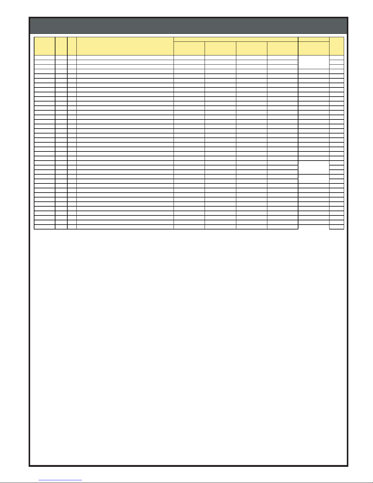
BILL OF MATERIAL
32
STAR
WM VSH60LMCSFU
WM VSH60PMCSFU
WM VSH60EMCSFU
WM VSH60AMCSFU
WM VST60LMWSFU
ASSY,BASE A ,KSA-601P,VG GREY 1200027700 1200024011 1200024198 1200024187 1200032261
1120 1 PC BASE A,KSA-601OP,VG GREY 1200027701 1200024030 1200024207 1200024196 1200032304 Y
1130 3 PC W ASHER B,MOTOR,741 1100001074 1100001074 1100001074 1100001074 1100001074
1140 1 PC MOTOR,105W,ALUMINIUM WIRE 1100029770 1100029770 1100029770 1100029770 1100029770 Y
1150 3 PC UNIT,MOT OR WASHER A,613,SA63/43 1100019019 1100019019 1100019019 1100019019 1100019019
1160 3 PC SCREW ,SPECIAL,TAPPING,515,6800 1100005286 1100005286 1100005286 1100005286 1100005286
1170 1 PC W IRE,ASSY,EARTH 1100029760 1100029760 1100029760 1100029760 1100029760
1180 2 PC SCREW ,5X12 1100005279 1100005279 1100005279 1100005279 1100005279
1190 1 PC FAN,MOTOR PULLY,MULTIE 6000 1200019626 1200019626 1200019626 1200019626 1200019626 Y
1200 1 PC PULLEY,MOTOR,MULTIE 6000 1100029815 1100029815 1100029815 1100029815 1100029815 Y
1210 3 PC SCREW ,PAN HEAD,M4X8,BUILT IN WASHER 1100029757 1100029757 1100029757 1100029757 1100029757
1220 1 PC SCREW ,STOP,XXE08C12,SA63 1100000931 1100000931 1100000931 1100000931 1100000931
1230 1 PC BRAKE W HEEL,CI,60MM,MULTIE 6800,WTH BOLT 1100034613 1100034613 1100034613 1100034613 1100034613 Y
1250 1 PC UNIT,SPIN MOTOR PLATE SA63 1100019011 1100019011 1100019011 1100019011 1100019011 Y
1260 1 PC BRAKE SPRING W M 1100024186 1100024186 1100024186 1100024186 1100024186
1270 3 PC SCREW ,PAN HEAD,XSN4+6S,6800 1100005282 1100005282 1100005282 1100005282 1100005282
1280 1 PC MOTOR,45W,ALUMINIUM WIRE 1100029769 1100029769 1100029769 1100029769 1100029769 Y
1290 3 PC ASSY,SUSPENSION,FA61 1200006071 1200006071 1200006071 1200006071 1200006071 Y
1300 3 PC SCREW ,SPECIAL,TAPPING,25A 1100006698 1100006698 1100006698 1100006698 1100006698
1310 1 PC CAPACITOR,FILM,240V,9.5+4.0MFD,J 1100005220 1100005220 1100005220 1100005220 1100005220 Y
1320 2 PC PAD,RUBBER,LEG,5KG,MULTIE 6000 1100029798 1100029798 1100029798 1100029798 1100029798
1330 2 PC CASTOR WHEEL,SA63,MULTIE 6800 1100005221 1100005221 1100005221 1100005221 1100005221
1340 4 PC SHAFT,CAST OR,MULTIE 6800 1100005290 1100005290 1100005290 1100005290 1100005290
ASSY,PANEL A,VSH60LMC,SHINE,LIGHT GREY 1200035273 1200035274 1200035272 1200035271 1200035266
1350 1 PC PANEL A,SHINE,GREY,PRINTED,LIGHT GREY 1200035281 1200035282 1200035280 1200035279 1200035439 Y
1360 1 PC HOLDER,W ASH TIMER,MULTIE 6000 1200019621 1200019621 1200019621 1200019621 1200019621
1370 1 PC TIMER,W ASH,35MIN,2SHAFT,MOTORISED,6000 1100029825 1100029825 1100029825 1100029825 1100029826 Y
1380 1 PC HOLDER,CYCLE SELECTOR,MULTIE 6000 1200019623 1200019623 1200019623 1200019623 1200019623
1390 1 PC SCREW ,SPECIAL,TAPPING,BUILTIN WASHER,414 1100000916 1100000916 1100000916 1100000916 1100000916
1400 1 PC LEVER,CYCLE,SELECTOR,MULTIE 6000 1200019599 1200019599 1200019599 1200019599 1200019599 Y
1410 1 PC SPRING,FLAT,50.5MM,6800 1100005295 1100005295 1100005295 1100005295 1100005295
1420 0.7 M POLYESTER ST RIP,6MMX2000M 1100009335 1100009335 1100009335 1100009335 1100009335
1430 1 PC HOLDER,SPIN TIMER,MULTIE 6000 1200019622 1200019622 1200019622 1200019622 1200019622
1440 1 PC TIMER,SPIN,MULTIE 6000/6800 DLX 1100019531 1100019531 1100019531 1100019531 1100019531 Y
1450 1 PC BUZZER,AC,18V ,W M 1100000589 1100000589 1100000589 1100000589 NR
1460 2 PC SCREW ,BIND,TAPPING,XTB3+12C,SA63/6800 1100006701 1100006701 1100006701 1100006701 NR
1470 4 PC KNOB,TIMER,DECO,MULTIE 6000,LIGHT GREY 1200032314 1200023874 1200023874 1200023874 1200032314 Y
1480 4 PC INSERT,T IMER DECO,MULTIE 6000,CHROMPLATE 1100036877 1100036877 1100036877 1100036877 1100049398 Y
Exploded
view code
Qty Unit Object description
SHINE
SBOM
Page 34
 Loading...