

Videocon MST719, MST719DU Service Manual
MST719 Service Manual
[SERVICE MANUAL]
Mstar MST719DU
1
MST719 Service Manual
Contents
1. Introduction chassis block diagram ----------------------------------4
2. MST719 IC Introduction ------------------------------------------5
1) Features description ------------------------------------------5
2) Pins function description -- -----------------------------------7
3. TAS5707 IC Introduction -----------------------------------------13
1) Features description -----------------------------------------13
2) Pins function description --------------------------------------15
4. TDA9885TS IC Introduction ---------------------------------------17
1) Features description -----------------------------------------17
2) Pins function description --------------------------------------21
5. PCM1808 ADC IC Introduction--------------------------------------22
6. SN74LVC1GX04DCK IC Introduction ---------------------------------23
7. EN25F40 IC Introduction ------------------------------------------24
8. CS4344 IC Introduction ------------------------------------------25
9. Other ICs introduction ------------------------------------------26
10. Connectors and electronics parameter-------------------------------27
11. Usual fault-------------- -------------------------------------30
1) Can’t work-------------------------------------------------30
2) Back lamp can’t be on----------------------------------------31
3) Image abnormity --------------------------------------------32
4) No sound--------------------------------------------------33
2
!
1. warning!
MST719 Service Manual
High voltage , don’t touch it when it’s working
2. Please confirm the power to Panel is +5V when change main board, if not ,the panel
can’t work or be damage
3
MST719 Service Manual
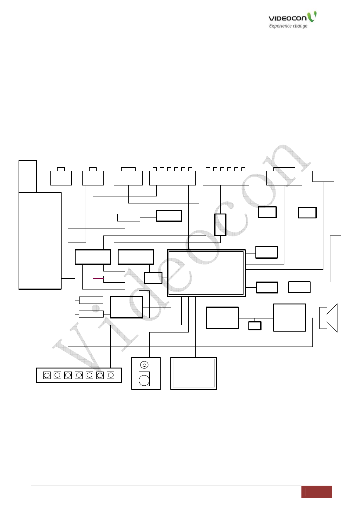
1. Introduction chassis block diagram
MST719 chassis is composed of power management,Tuning circuit, IF Amplifier circuit, TDA9885 is the IF-PLL demodulators,
CVBS and Sound decode,video processing circuit. The MST719DU is the main IC combines the functions of 2D comb filter Decode
and 2De-Interlacing ,µ-controller. ADC and Scaling . Integration one HDMI. TAS5707 is the sound processor and Sound amplifier.
The block diagram as follow:
Tuner
PAL/SECAM
BG/DK
U9
VGA_AI
VGA_Auido
U14
Audio switch
IF
X1
K9656M30
X2
K3953M30
KEY Board
HP
Headphone_Out
DVD R&L
TV Au dio
S-Video YPbPr&AV1
Audio R&L
Y / C
DVD socket
DVD socket
NXP
TDA9885TS
CN10
74HC4052D74HC4052D
Audio switch
YPbPr
CVBS
Audio R&L Out
U26
CN8
U10
IR Board
PI5V330
DVD switch
U13
CS4344
HDMI DAC
CVSB
Audio Out AMP
LED
IR
CVBS
YPbPr
U6
MSTAR IC
MST719DU
2D Combf ilter
2D interlace
LCD Panel
AV2&AV_OUT
Audio R&L
Audio out
CVBS
RC4558
U4
U18
ADC
PCM1808
U27
SN74LVC1GX04DCK
VGA
CVBS_Out
U7 U8
24C04
HDMI
24C04
Power
Connect LIPS
FLASH
EN25F40
U20
U16
U19
24C04
HDCP
CN21
Speaker
2 X 5W
24C32
EEPROM
U28
U21
Sound
processor&
TAS5707
4
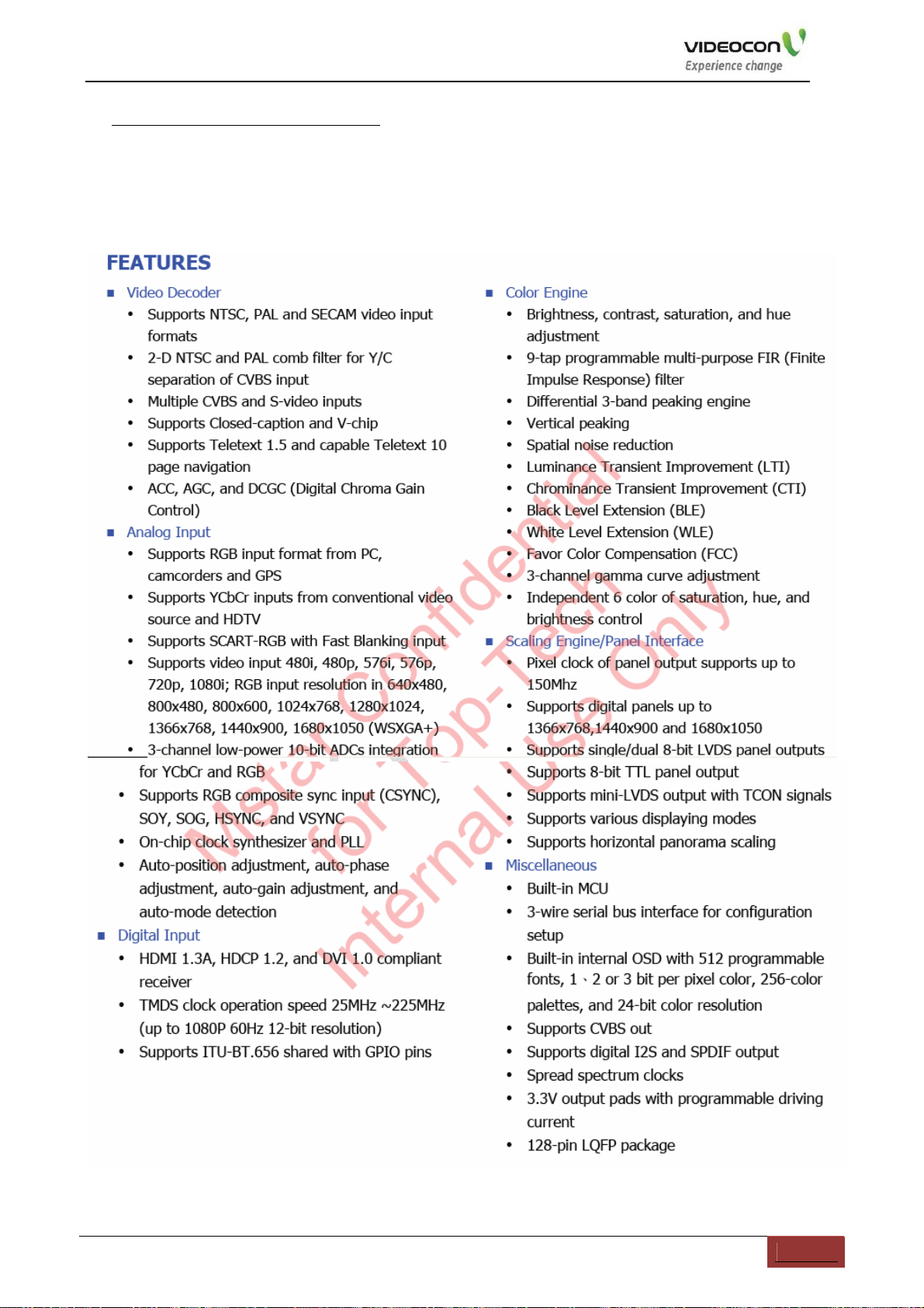
2.MST719 IC Introduction
1).features description
MST719 Service Manual
5
MST719 Service Manual
6
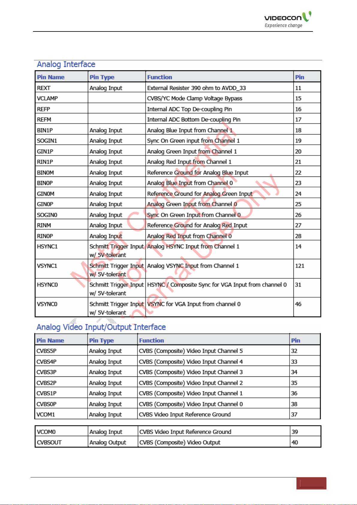
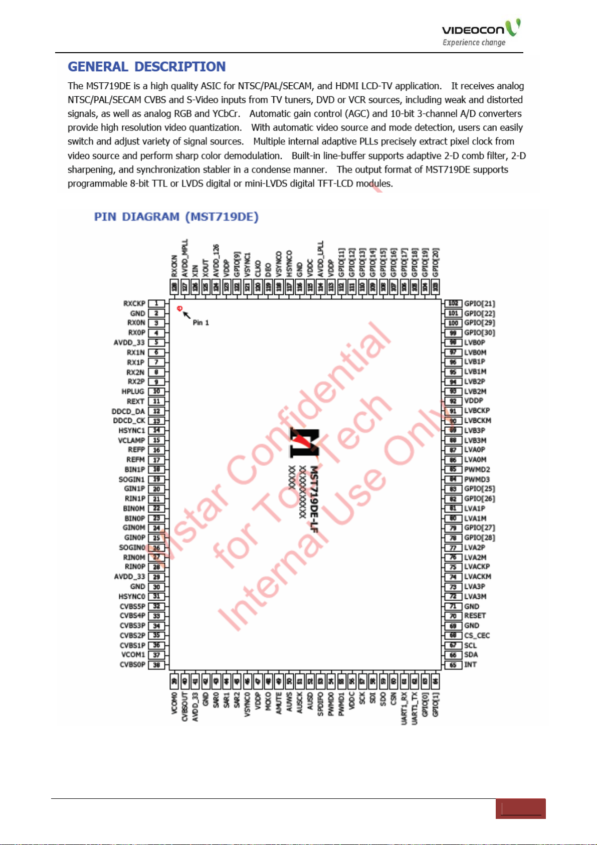
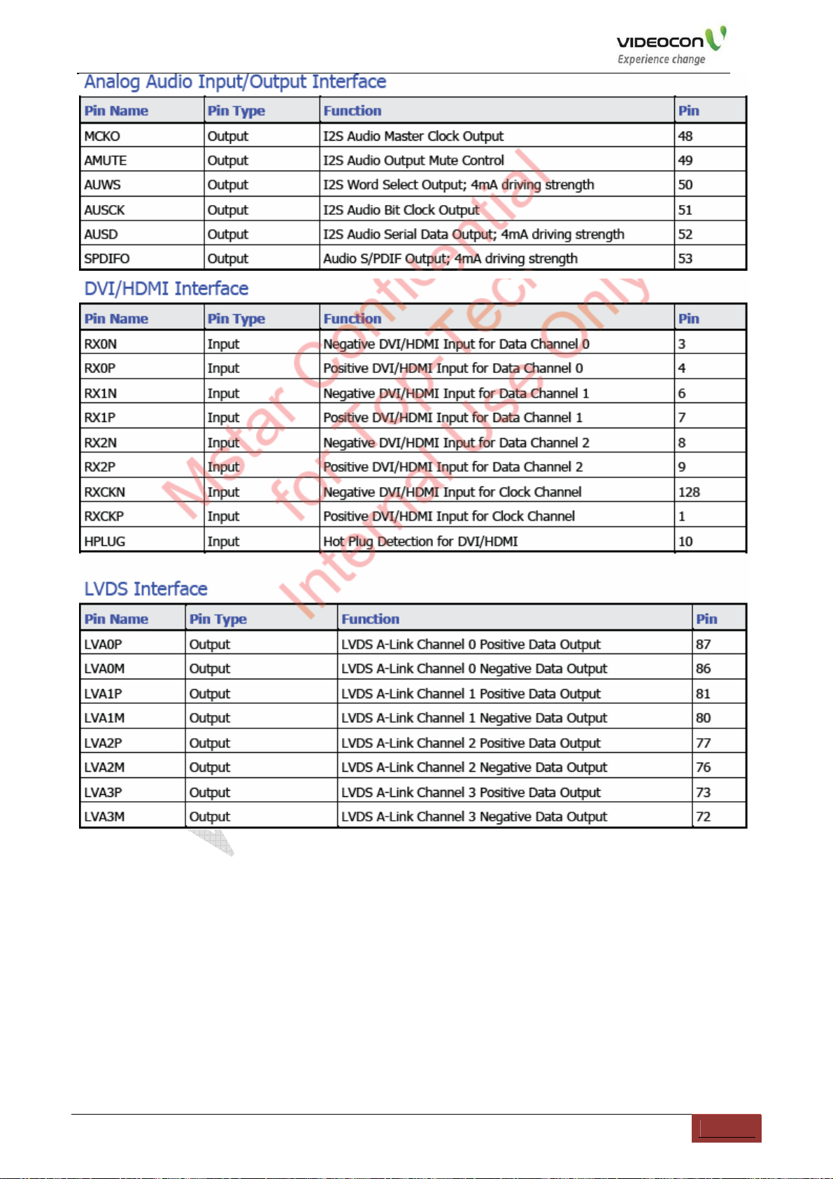
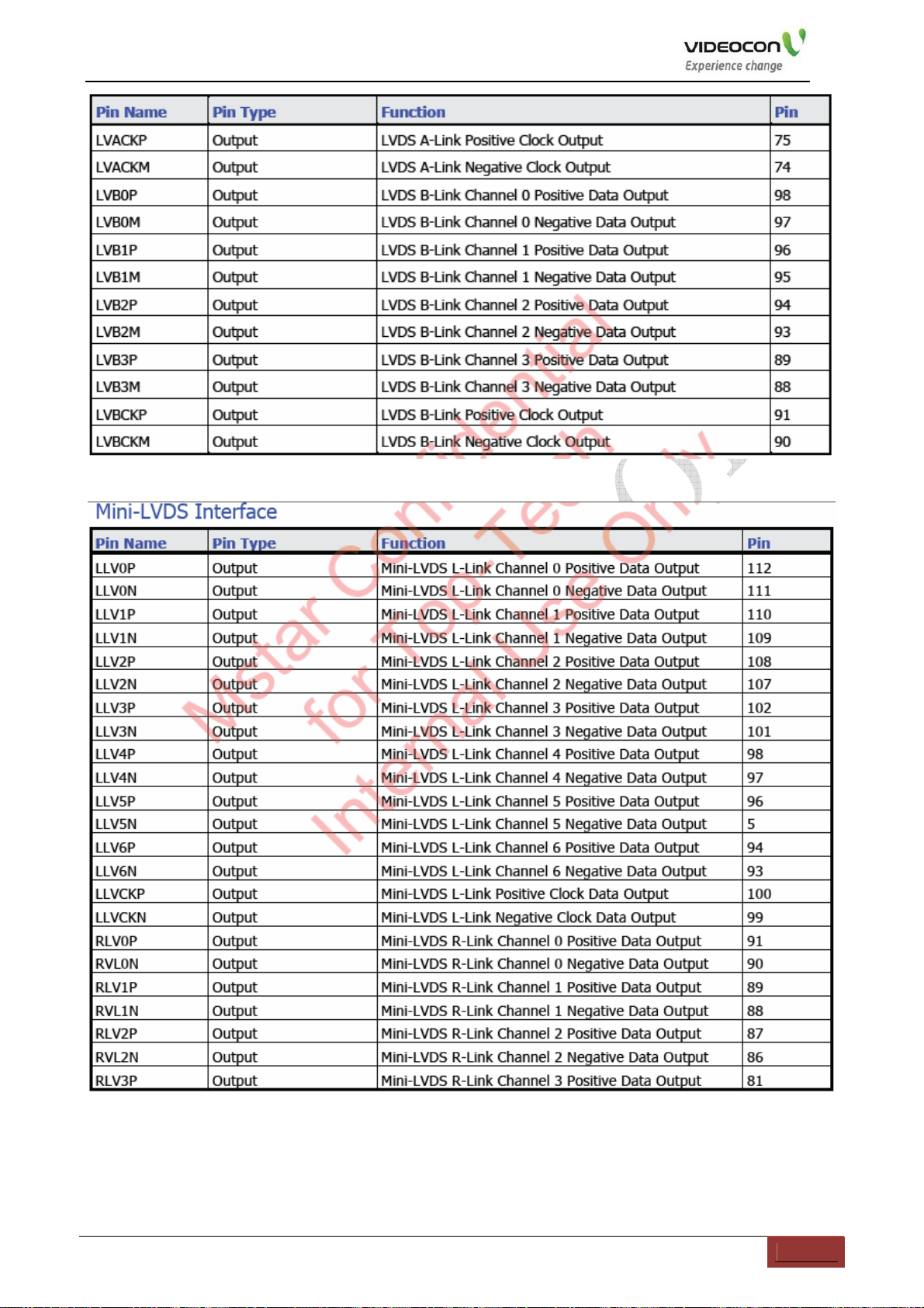
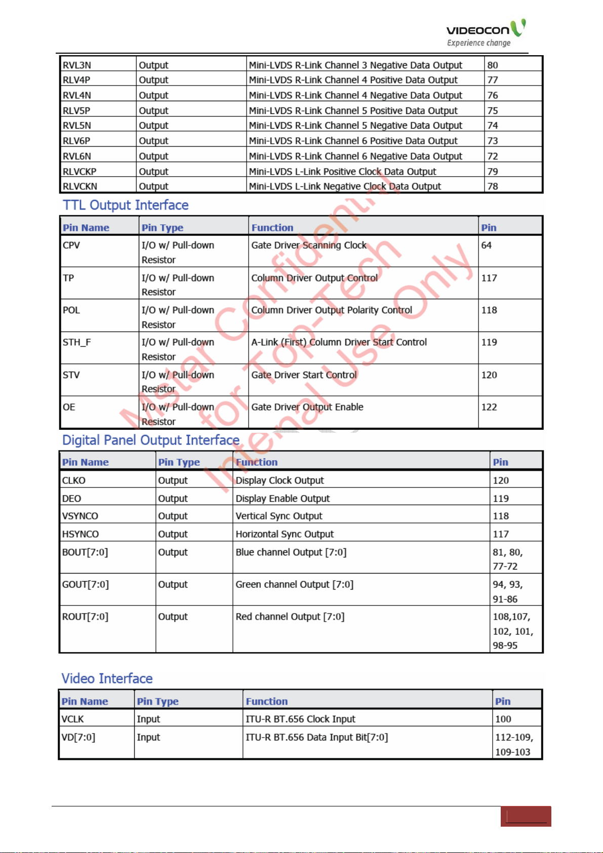
2) Pins function description
MST719 Service Manual
7
MST719 Service Manual
8
MST719 Service Manual
9
MST719 Service Manual
10
 Loading...