

VideoComm Technologies TCO-5808 series, TCO-5808T3, TCO-5808R6, TCO-5808Q4, TCO-5808Q9 Owner's Manual

5.8GHz All Weather 8 Channel Series Manual Rev. J
5.8GHz All Weather 8 Channel Series
Manual Rev-J
OWNER’S MANUAL
VideoComm Technologies – “The Freedom of Wireless”
(888) 379-2666 US Toll Free
(905) 339-0366 Phone
(905) 339-1776 Fax
http://www.videotransmitters.com/
info@VideoTransmitters.com
1

5.8GHz All Weather 8 Channel Series Manual Rev. J
TABLE OF CONTENTS
TABLE OF CONTENTS.............................................................................................. 2
SAFETY NOTICES...................................................................................................... 3
INTRODUCTION ........................................................................................................ 4
Advantages ………………………………………………………………………………………………………..4
PARTS LIST................................................................................................................. 5
PRE INSTALLATION................................................................................................. 6
Site Evaluation.....................................................................................................................................6
Identify line-of-sight ......................................................................................................................6
Up & in the clear............................................................................................................................6
Ground Plane................................................................................................................................. 6
Trees Grow!...................................................................................................................................7
Unusual Traffic..............................................................................................................................7
Things that block transmission....................................................................................................11
Alignment & GPS Use .................................................................................................................11
Tools Required................................................................................................................................... 12
Opening & Closing The All Weather Enclosure .................................................................................. 13
Video Cable Installation & Termination ............................................................................................. 14
Video and Audio Cable Installation & Termination.............................................................................15
Terminating External Antenna Cable................................................................................................. 16
Terminating External Antenna – Video – Audio Cables..................................................................... 16
Unused Grommet Seals ...................................................................................................................... 17
Power Supply Connection...................................................................................................................18
Power-Up Device............................................................................................................................... 19
Channel Selection...............................................................................................................................20
Antenna Polarization..........................................................................................................................21
Multiple Link Antenna Polarization .................................................................................................... 24
Conducting a Bench Test....................................................................................................................25
INSTALLATION........................................................................................................ 27
Pole Mounting the 5.8GHz All Weather Series.................................................................................... 27
Wall Mounting the 5.8GHz All Weather Series....................................................................................30
Enclosure Alignment and Positioning ................................................................................................. 31
TIPS & TROUBLE SHOOTING............................................................................... 32
OPTIONAL PRODUCTS & ACCESSORIES .......................................................... 34
SPECIFICATIONS .................................................................................................... 35
WARRANTY INFORMATION/ TERMS & CONDITIONS .. 36
2

5.8GHz All Weather 8 Channel Series Manual Rev. J
SAFETY NOTICES
I. THIS DEVICE COMPLIES WITH FCC RULES PART 15. OPERATION IS SUBJECT
TO THE FOLLOWING TWO CONDITONS:
(1) This device may not cause harmful interference, and
(2)
may cause undesired operation of the device
II. In order to comply with the FCC/IC adopted RF exposure requirements, this transmission
system will be installed by an authorized professional installer of VideoComm
Technologies. Installation of all antennas must be performed in a manner that will provide
at least 23cm clearance from the front radiating aperture, to any user or member of the
public.
This device must accept any interference, including interference that
III. This is NOT an intrinsically safe device. Do not take into area where intrinsic safety is
required. Bodily harm may result if warning is ignored.
IV. DO NOT OPERATE TRANSMITTER WITHOUT ANTENNA CONNECTED TO
ANTENNA PORT. Failure to do so will result in damage to the unit and void the
warranty.
V. DO NOT OPERATE THE TCO-5800 SYSTEM WHEN the Transmitter & Receiver are
closer than ten feet to each other. The devices may not work properly and permanent
damage can occur.
VI. The TCO-5800 has been certified by the FCC for use with other products without any
further certification (as per FCC section 2.1091.) Changes or modifications not expressly
approved by VideoComm Technologies could void the user’s authority to operate the
equipment.
The term “IC:” before the radio certification number only signifies that Industry Canada
Technical specifications were met.
3
5.8GHz All Weather 8 Channel Series Manual Rev. J
INTRODUCTION
Introduction
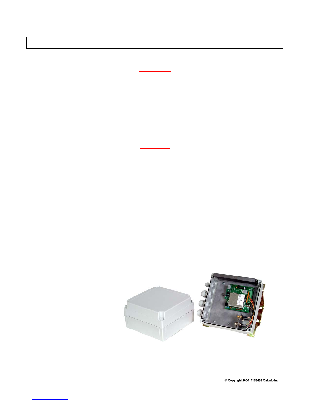
Designed with the harshest environments in mind, the robust TCO-5808 series delivers high resolution,
real time video in applications ranging from a few hundred feet up to many miles, depending on
system. Its rugged IP-67 all-weather enclosure transmits in applications where trenching cable may not
be possible, convenient or economical. Operating in the unlicensed 5.8GHz ISM band, this unit
features eight user selectable channels and includes a universal mounting bracket system for a variety
of mounting scenarios.
Advantages
•
Easy to install and operate.
•
8 user selectable channels.
Internal Transmitters & Receiver Antennas. ( TCO-5808Q9 has external Rx antenna )
•
•
Delivers high resolution, real time video
Range from 2000 feet to 4 miles line of sight (depending on system & antenna)
•
•
Less susceptible to wireless data networks and other devices
Rugged all weather IP-67 protective enclosure.
•
•
Perfect for commercial, industrial, scientific, law enforcement and government video
security applications.
VideoComm Technologies
Customer Service
Bus (905)-339-0366
US Toll Free 888-379-2666
Fax (905)-339-1776
E-mail- info@VideoTransmitters.com
Web Site- www.VideoTransmitters.com
Monday - Friday 8:30am- 5:30pm
Eastern Standard Time
4
5.8GHz All Weather 8 Channel Series Manual Rev. J
PARTS LIST
The 5.8GHz All Weather 8 Channel Series has been carefully manufactured, tested, inspected and
packaged. Please inspect the packaging carefully to ensure you have received all the necessary parts
and accessories listed. Refer to the following chart to determine which parts are included with your
product. If any parts are missing or damaged, contact VideoComm Technologies, Customer Service
or your re-seller immediately.
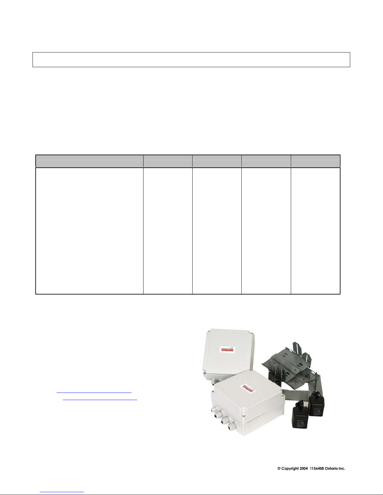
The TCO-5800 All Weather Video Transmission system comes complete with the following items:
PARTS TCO-5808T3 TCO-5808R6 TCO-5808Q4 TCO-5808Q9
1 X Transmitter Unit
1 X Receiver Unit
4 X Grommet Seal s Plugs
8 X Plastic Lid Screws
2 X Universal Mounting Brackets
2 X 12VDC 500mA Power Supplies
3dB Inter nal Transmit Antenna
6ft. LMR-200 Antenna Cable
6dB Internal Receiver Antenna
14dB Internal Receiver Antenna
29dB External Receiver Antenna
VideoComm Technologies
Customer Service
Bus (905)-339-0366
US Toll Free 888-379-2666
Fax (905)-339-1776
E-mail- info@VideoTransmitters.com
Web Site- www.VideoTransmitters.com
Monday - Friday 8:30am- 5:30pm
Eastern Standard Time
X X X X
X X X X
X X X X
X X X X
X X X X
X X X X
X X X X
OPTIONAL X
OPTIONAL X
OPTIONAL X
OPTIONAL X
5

5.8GHz All Weather 8 Channel Series Manual Rev. J
PRE INSTALLATION
Site Evaluation
Identify line-of-sight
Although wireless video transmission may seem like a viable option for a particular application at first
glance, there are many considerations. Is there a clear, unobstructed view between the transmitter and
receiver? Are there any other devices that may cause interference? Depending on the height of the
building, tower or structure, you must consider the path that the wireless video will travel between the
transmitter and receiver. Line-of –sight is defined as a clear and unobstructed view between the
transmitter and receiver.
Up & in the clear
To realize the optimum distance for your VideoComm Technologies wireless devices, “give them
some air”. The radio waves coming from your TCO-5800 system antennas do not shoot out like a laser
beam, rather they radiate from the antenna like a flash light beam. Therefore the transmitter and
receiver should both be up and in the clear. A good rule of thumb is to mount the devices at least 15 to
20 feet above obstructions, like the roof of a building, the roofs parked cars in a parking lot, or top of a
fence line.
See Figure 2.
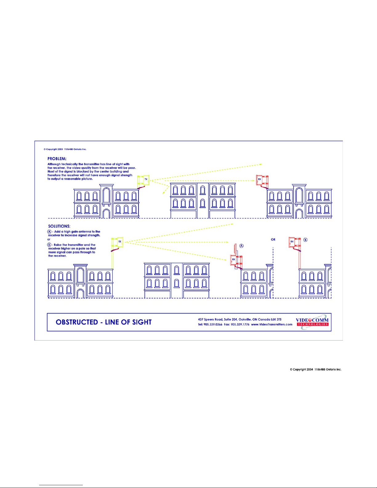
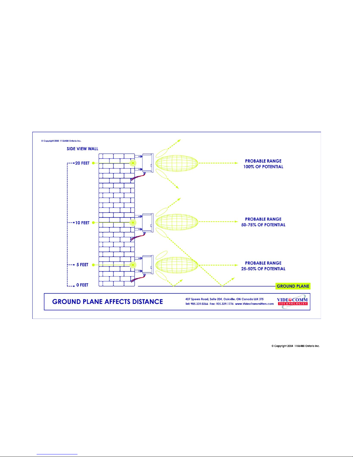
Ground Plane
If the radio devices are not mounted high enough above obstructions, the signal strength will be
seriously reduced; therefore your distance will be reduced. The signal will literately bounce up and
away from your intended target. This is known as a negative ground plane effect. The ground plane
could not only be the ground you stand on, but could also be the rooftops of cars or distant buildings.
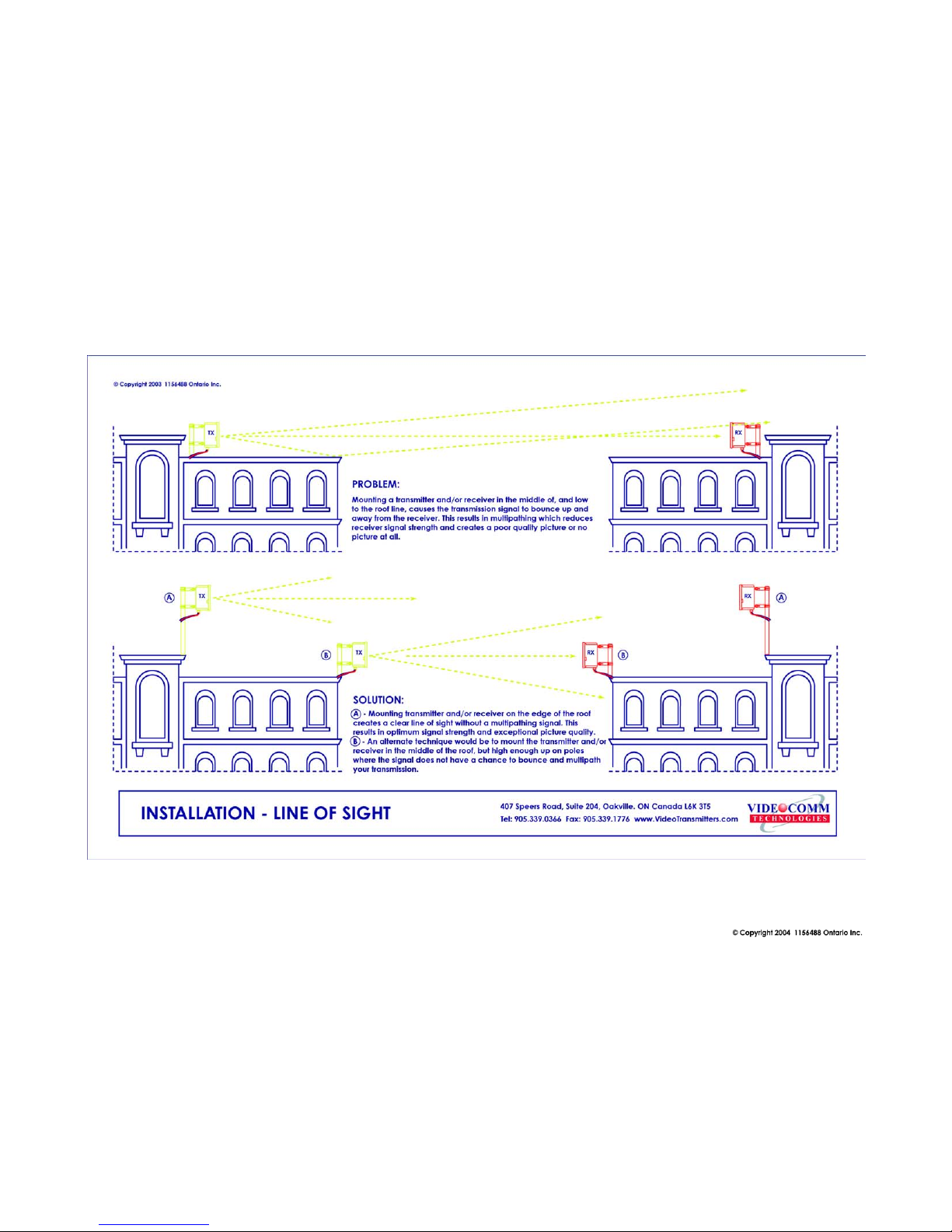
See Figure 3. If we have a choice, place the transmitter/receiver enclosures, or if external antenna, on
the edge of the roof looking AWAY from the building, rather than installing them in the middle of the
roof , shooting across the top of the roof. See Figure 4. This is particularly important if we have a
metal roof that tends to deflect signals away from the target. Also consider any obstruction that may
get in the way, like another roof or a tractor-trailer that may pass through your “line of sight”..
6
5.8GHz All Weather 8 Channel Series Manual Rev. J
Trees Grow!
If we install the video link in the winter, the leaves that come out in spring may eliminate your wireless
link. Are you trying to transmit through trees? Then you will need to seriously consider how much
range will be lost. A field test is always the best way to find out. Speak to a VideoComm Technologies
Tech for a possible solution.
Unusual Traffic
Watch out for unusual traffic in your transmission path. For example, a dump truck with the back
elevated while dumping a load can be much taller than expected. Tractor-trailers or other large vehicles
may be a factor if trying to transmit over a highway. Metal obstructions between the antennas cannot
be ignored including electrical transmission lines that may not be obvious in the distance. Each high
voltage wire crossing your path can be the equivalent of transmitting past an eight-foot thick steel pipe.
Microwave towers may look fragile, but they can be as good as or equal to a solid steel door for
blocking transmission.. The higher the transmitter and receiver are in the air, the higher the success
rate.
VideoComm Technologies
Customer Service
Bus (905)-339-0366
US Toll Free 888-379-2666
Fax (905)-339-1776
E-mail- info@VideoTransmitters.com
Web Site- www.VideoTransmitters.com
Monday - Friday 8:30am- 5:30pm
Eastern Standard Time
7
5.8GHz All Weather 8 Channel Series Manual Rev. J
8
5.8GHz All Weather 8 Channel Series Manual Rev. J
9
5.8GHz All Weather 8 Channel Series Manual Rev. J
10

5.8GHz All Weather 8 Channel Series Manual Rev. J
Things that block transmission
Things that block transmission are not always obvious. Here are some of the most
common pitfalls:
• Water, or anything with water in it (people are 98% water). Snow & rain can
reduce your distance.
• Steel, or anything with steel in it---steel-reinforced concrete (rebar) or metal
window screens, or a tool-room cage. Aluminum siding, and energy-saving
foil on the insulation in the walls are sneaky killers for radio waves. Some
metallic paints or metallic wallpapers also block signals.
• Mirrors block transmission, because the “mirror” consists of a metallic
backing on the glass.
• Lead windows will kill radio transmission; also windows that are UV coated
may have thin metal energy-saving film.
• High Voltage transmission lines (physically they look small, but for video
transmission purposes, they might as well be 6-foot diameter metal sewer
pipes.
• Other materials like brick, drywall or wood, will also cut down on the signal,
depending on water content.
Alignment & GPS Use
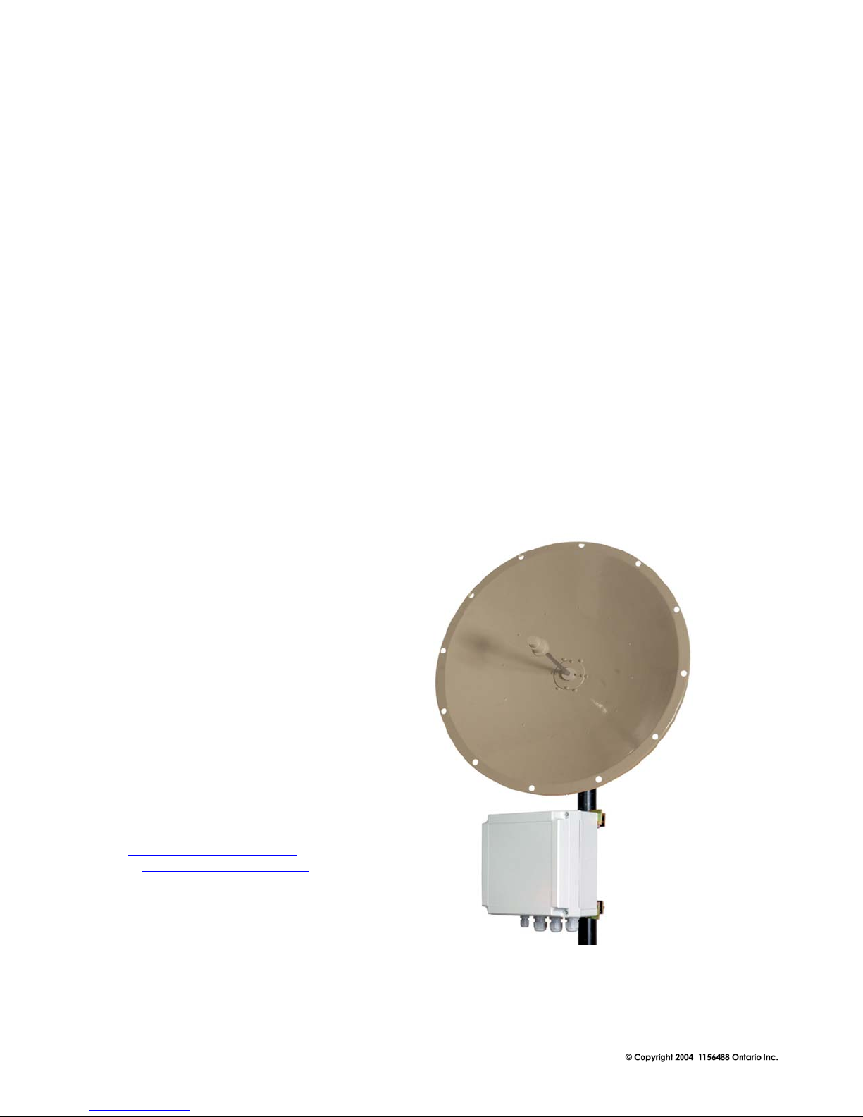
As the 5.8GHz All Weather 8 Channel Series utilizes directional antennas and it is
important for both antennas to be “looking at each other”. Height of the antennas is also a
factor. The antennas should have no more than a 10-foot variance in height. If the
transmit antenna is 25ft. up high we would want the receiver antenna mounted at
approximately the same heights. This allows for the receiver antenna to receive main lobe
of the transmitted signal.
The longer the wireless video transmission range is, the more critical the alignment of
BOTH antennas. Once we get over a one-mile range, the alignment may well be
measured only in a few degrees, in any direction (up or down, as well as left or right).
Consider using a portable Global Positioning Satellite (GPS) receiver unit to determine
the transmitter and receiver angles accurately. A GPS looks a bit like a hand-held
calculator, and it lets us “learn” the longitude and latitude, relative to a group of satellites
overhead. We can input a value for both the transmitter and for the receiver and then
instruct the GPS to give us the compass bearings between the two points With a GPS
system a 10-mile unit can be aligned faster than a 1-mile unit aligned “by eye”.
11
 Loading...