

VideoComm Technologies EAT-002 (PARA-5829) Owner's Manual

5.8GHz Parabolic Antenna Manual Rev. A 2006
Model # EAT-002 (PARA-5829)
5.8GHz 29dB Parabolic Antenna
Manual Rev-A
OWNER’S MANUAL
It’s About Real-Time
1
5.8GHz Parabolic Antenna Manual Rev. A 2006
Antenna Assembly & Mounting
The longer the wireless video transmission range is, the more critical the alignment of BOTH the
transmitter and receiver antenna. If transmitting over one-mile in range, the vertical or horizontal
adjustment of the antennas can be measured in a few degrees. Consider using a portable Global
Positioning Satellite (GPS) receiver unit to determine the transmitter and receiver angles
accurately. Input the value for both the transmitter and for the receiver and then instruct the GPS
to give us the compass bearings between the two points with a GPS system a 10-mile unit can be
aligned faster than a 1-mile unit installed by “eye”.
Specifications:
Frequency Range 5.725 - 5.850 GHz
Antenna Gain 29 dBi
H-Plane Beamwidth 6 degrees
E-Plane Beamwidth 6 degrees
Antenna Connector N-Female
Mounting Brackets Maximum 3” Diameter Pole
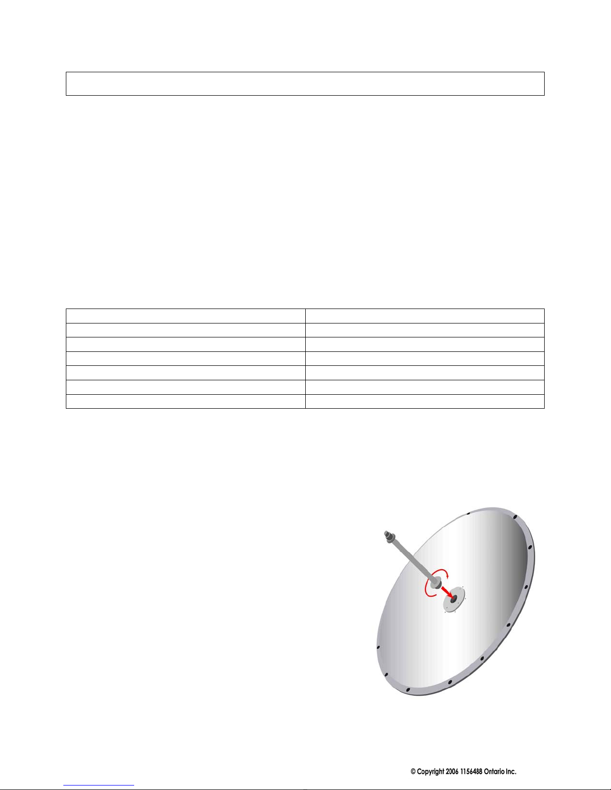
STEP ONE
Screw antenna element Rod into front dish.
2
 Loading...