

Page 1

# MX-5842c # MXR-5842c
# MX-5847VF # MXR-5847VF
MXR-5842-47 Series Manual Rev. C 2010
5.8GHz Wireless Camera Series
It’s About Real-Time
OWNER’S MANUAL
VideoComm Technologies
(888) 379-2666 US Toll Free
(905) 339-0366 Phone
(905) 339-1776 Fax
http://www.VideoTransmitters.com/
1
Page 2

MXR-5842-47 Series Manual Rev. C 2010
TABLE OF CONTENTS
TABLE OF CONTENTS..............................................................................2
SAFETY NOTICES......................................................................................2
INTRODUCTION.........................................................................................3
PARTS LIST..................................................................................................4
SYSTEM SETUP...........................................................................................5
Camera Power Supply Options..................................................................................................................5
Channel Selection.......................................................................................................................................6
Receiver Setup ............................................................................................................................................7
Camera Bracket Mounting - Ceilling.........................................................................................................8
Camera Bracket Mounting - Wall.............................................................................................................. 9
TIPS & TROUBLE SHOOTING..............................................................10
SPECIFICATIONS.....................................................................................11
WARRANTY INFORMATION/ TERMS & CONDITIONS ................12
SAFETY NOTICES
I. THIS DEVICE COMPLIES WITH FCC RULES PART 15.249 OPERATION IS SUBJECT TO THE FOLLOWING TWO
CONDITONS:
(1) This device may not cause harmful interference, and
(2) this device must accept any interference, including interference that
may cause undesired operation of the device
II. In order to comply with the FCC/IC adopted RF exposure requirements, this transmission system will be installed by an
authorized professional installer of VideoComm Technologies. Installation of all antennas must be performed in a manner
that will provide at least 23cm clearance from the front radiating aperture, to any user or member of the public.
III. This is NOT an intrinsically safe device. Do not take into area where intrinsic safety is required. Bodily harm may result if
warning is ignored.
IV. DO NOT OPERATE WIRELESS CAMERA WITHOUT ANTENNA CONNECTED TO ANTENNA PORT. Failure to do
so will result in damage to the unit and void the warranty.
V. DO NOT OPERATE THE WIRELESS CAMERA WHEN the Receiver is closer than ten feet. The devices may not work
properly and permanent damage can occur.
VI. The device has been certified by the FCC for use with other products without any further certification (as per FCC section
2.1091.) Changes or modifications not expressly approved by VideoComm Technologies could void the user’s authority to
operate the equipment.
The term “IC:” before the radio certification number only signifies that Industry Canada
Technical specifications were met.
2
Page 3

MXR-5842-47 Series Manual Rev. C 2010
INTRODUCTION
Introduction
ALL NEW 5.8GHz wireless camera series offers an economical solution for real-time, high resolution
wireless video applications, that's not susceptible to interference from 2.4GHz 802.11 b/g data devices.
Featuring 8 user selectable channels, this wireless camera is an ideal choice when multiple wireless video
links are required for any portable, temporary or covert surveillance and monitoring applications. Perfect for
any indoor camera application including, office, warehouse, retail stores or nursery.
Advantages
• Easy to install and operate with all accessories included
• 8 user selectable channels
• NO interference from 2.4GHz 802.11 b/g data devices
• 5.8GHz low profile desktop receiver included with some models.
• High resolution CCD camera
• Low current consumption for convenient battery operation
• Range up to 300 feet indoors
• One Year Limited Warranty
• RoHS compliant models available upon request.
• Ideal for portable, temporary and covert surveillance or monitoring applications
VideoComm Technologies
Customer Service
Bus (905)-339-0366
US Toll Free 888-379-2666
Fax (905)-339-1776
E-mail- [email protected]
Web Site- www.VideoTransmitters.com
Monday - Friday 8:30am- 5:30pm
Eastern Standard Time
3
Page 4
MXR-5842-47 Series Manual Rev. C 2010
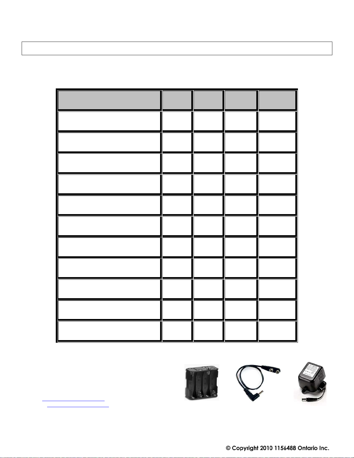
PARTS LIST
This 5.8GHz wireless camera system has been carefully manufactured, tested, inspected and packaged.
Please inspect the contents carefully to ensure you have received all parts and accessories listed. If parts are
missing or damaged, contact VideoComm Technologies Customer Service or your re-seller immediately.
PARTS
5.8GHz Color VariFocal Camera
5.8GHz Color Pinhole Camera
5.8GHz B&W Pinhole Camera
9VDC Power Supply – # PS-9300MX
AA Battery Pack Holder - # BP-900
9Volt DC Snap Cables - # A-BRL12VJK
Desk Top Receiver – # RX-5808
BNC-Male< to >RCA-Female adapter
12VDC Power Supply – # PS-1250
3dBi Duck Antenna - # RUB-5803
RCA Plug
VideoComm Technologies
Customer Service
Bus (905)-339-0366
US Toll Free 888-379-2666
Fax (905)-339-1776
E-mail- [email protected]
Web Site- www.VideoTransmitters.com
Monday - Friday 8:30am- 5:30pm Eastern Standard Time
MX-5842C
---
One
One
One
Two
---
---
---
---
MX-5847VF
One
---
---
One
One
Two
---
---
---
---
MXR-5842c
---
One
---
One
One
Two
One
One
One
One
One One
MXR-5847VF
One
---
---
One
One
Two
One
One
One
One
4
Page 5
MXR-5842-47 Series Manual Rev. C 2010
SYSTEM SETUP
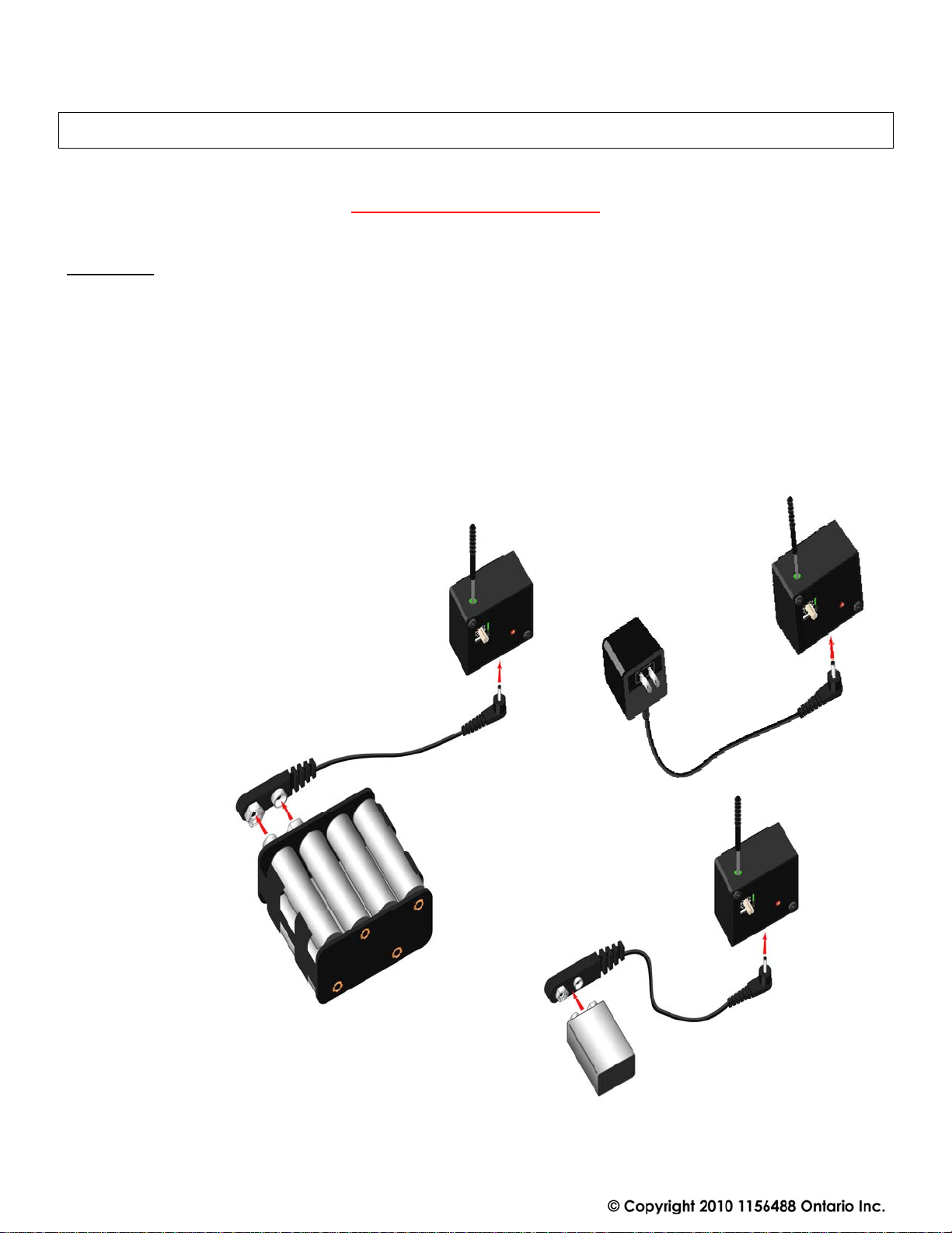
Camera Power Supply Options
WARNING – DO NOT OPERATE WIRELESS CAMERA WITHOUT ANTENNA CONNECTED TO
ANTENNA PORT. Failure to do so will result in damage to the unit and
1. Ensure the mini antenna is attached to the transmitter.
2. Power-UP wireless camera either with the included power supply or with a battery and power jumper
input cables. See examples below.
3. Connect the 1.3mm barrel jack into the bottom of camera. RED LED light will confirm power.
4. NOTE: The wireless camera does not have an ON-OFF switch and therefore the moment you connect
a power source to the wireless camera, it is operational. Important if using a battery supply.
5. See specifications for operating voltage range. Higher than 13VDC can permanently damage the
wireless camera. Lower than 8VDC of operating voltage, the camera may not work.
6. Adjust camera focus as required
7. Do Not bend the black part of the antenna
Wireless operation from Battery power source
is dependant on type and quality of batteries.
Call Tech Support for suggestions.
Only use a VideoComm Technologies power supply.
Model # PS-9300mx.
will void the warranty.
5
Page 6
MXR-5842-47 Series Manual Rev. C 2010
Channel Selection
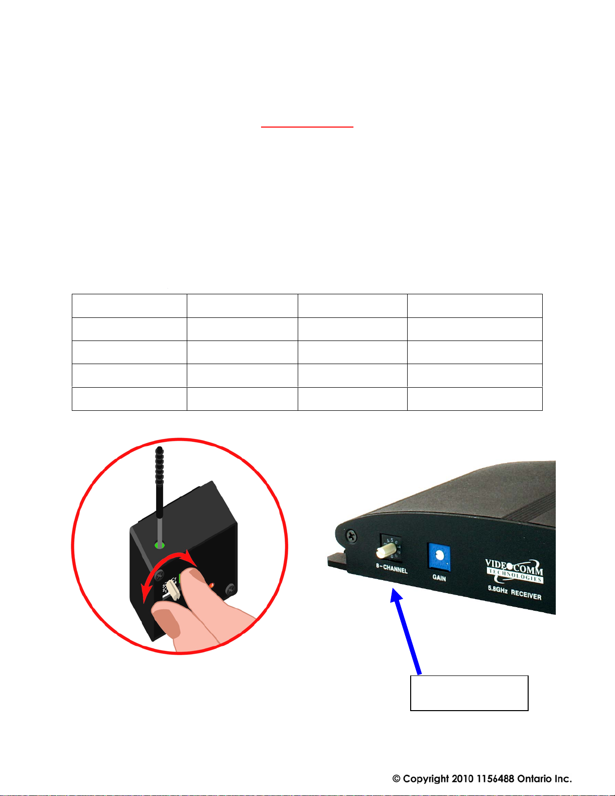
1. Set the desired channel by turning the rotary switch
2. This can be done with a small flat-head screw driver or with your fingers.
3. Do not push in the rotary switch knob, permanent damage can occur.
4. Repeat these steps for the receiver. The receiver must have the same and matching channel as the
wireless camera to receive the video signal.
5. Do Not bend the black part of the antenna.
Channel # 1 5.733 GHz Channel # 6 5.828 GHz
Channel # 2 5.752 GHz Channel # 7 5.847 GHz
Channel # 3 5.771 GHz Channel # 8 5.866 GHz
Channel # 4 5.790 GHz Channel # 9 5.866 GHz
Channel # 5 5.809 GHz Channel # 0 5.733 GHz
Receiver Rotary
Switch
6
Page 7
MXR-5842-47 Series Manual Rev. C 2010
Not
Not
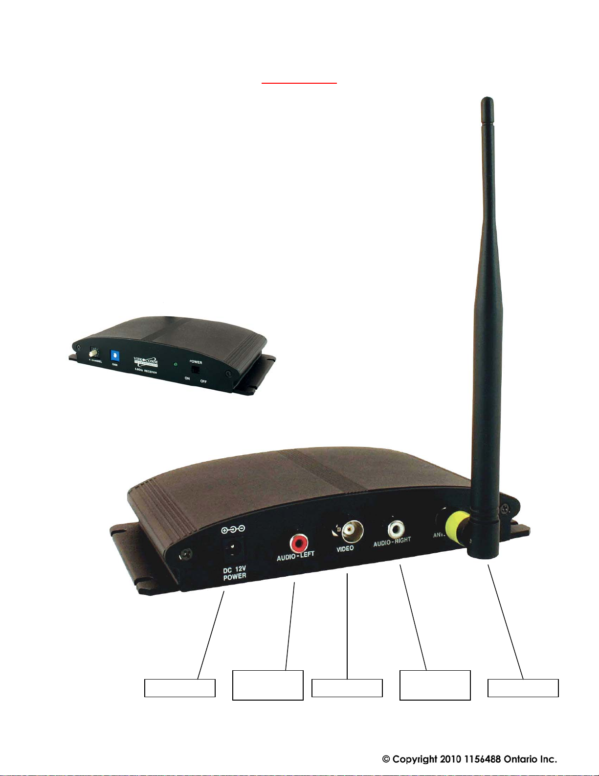
Receiver Setup
For the wireless link to work, both devices must have the same channel selected.
1. Attach the included rubber duck antenna to the SMA connector on receiver.
2. Power-UP the Receiver using the included power supply & switch to “ON”
3. Set the desired channel by turning the rotary switch to channels from 1 – 8
4. The receiver must be set to the same channel as the camera.
5. Connect video cable from receiver output connector to monitor source
6. We strongly recommend that you do not adjust the video gain adjustment without
first consulting a member of the VideoComm Technologies Tech Support Team.
2.1mm Barrel SMA-Female
RCA-Female
-Used
BNC-Female
RCA-Female
-Used
7
Page 8
MXR-5842-47 Series Manual Rev. C 2010
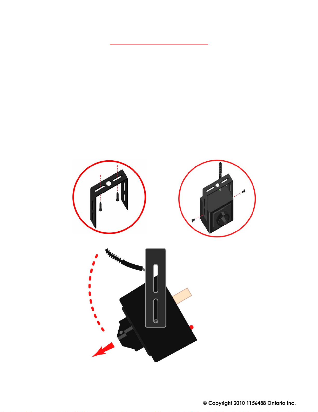
Camera Bracket Mounting - Ceilling
We recommend confirming system setup for power, channel selection and video picture before
permanently mounting the camera with the supplied bracket.
1. Mount the camera U-type bracket in the desired ceiling location using two screws – ( Not included )
We recommend using wall plugs to support the weight of the camera. ( Not Included )
2. Insert camera between U-type bracket and secure with mini screws - included
3. Pivot camera up-down as required to achieve desired video picture angle. Tighten mini screws for
permanent mount.
4. Plug in power supply source and re-confirm successful video picture. Add optional high gain receiver
antenna to improve distance or eliminate poor video signal reception.
5. Do Not bend the black part of the antenna
8
Page 9
MXR-5842-47 Series Manual Rev. C 2010
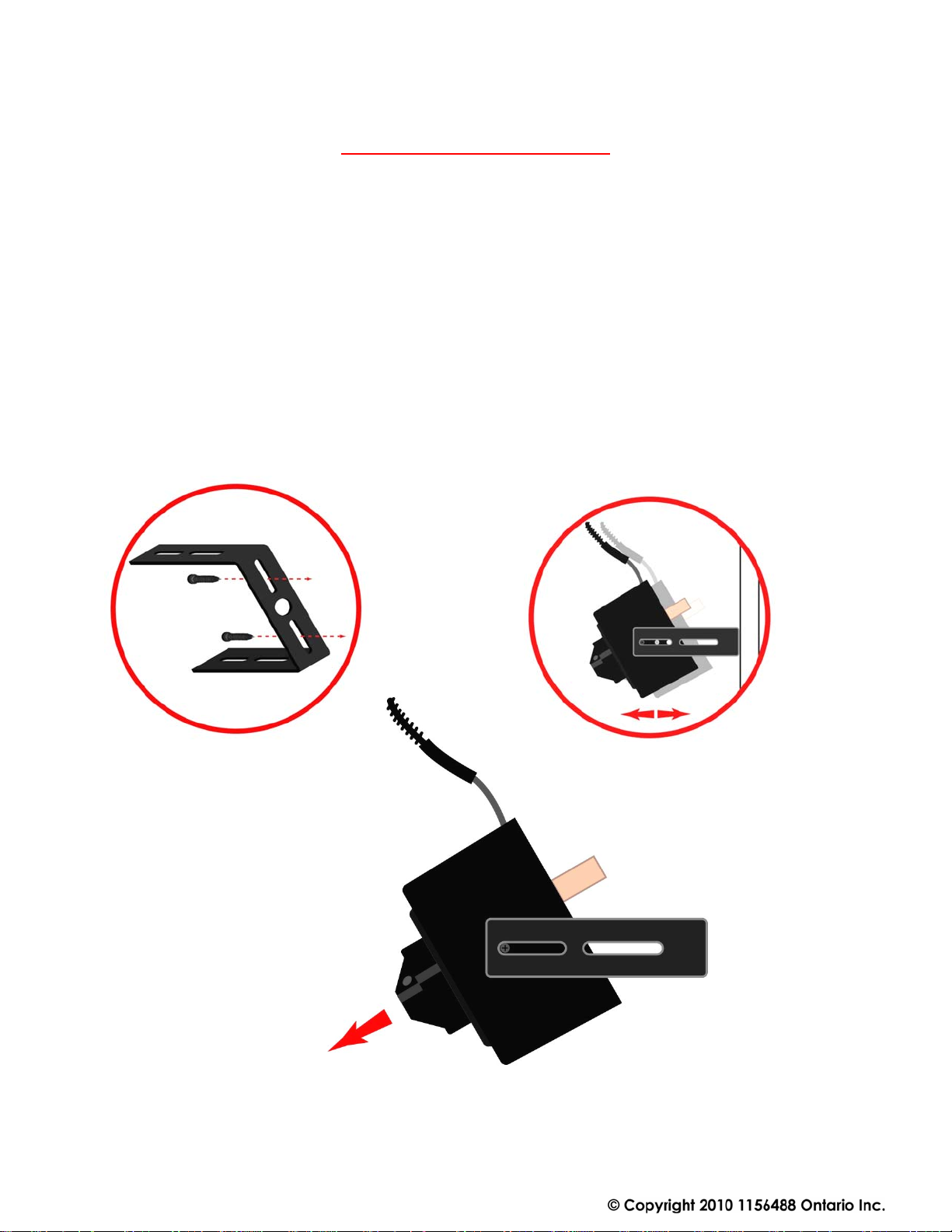
Camera Bracket Mounting - Wall
We recommend confirming system setup for power, channel selection and video picture before
permanently mounting the camera with the supplied bracket.
1. Mount the camera U-type bracket in the desired location using two screw s – ( Not included ) We
recommend using wall plugs to support the weight of the camera. ( Not Included )
2. Insert camera between U-type bracket and secure with mini screws - included
3. Pivot camera up-down as required to achieve desired video picture angle. Tighten mini screws for
permanent mount.
4. Plug in power supply source and re-confirm successful video picture. Add optional high gain receiver
antenna to improve distance or eliminate poor video signal reception.
5. Do Not bend the black part of the antenna
9
Page 10
MXR-5842-47 Series Manual Rev. C 2010
TIPS & TROUBLE SHOOTING
Things that block transmission
Things that block transmission are not always obvious. Consider any obstruction that may get in the way or
reduce the wireless signal strength along the way. Here are some of the most common pitfalls:
• Transmitting through walls in an office environment may be limited if the transmitting path has
many desks, computers and other office type equipment in it’s path. Raise the transmitter and
receiver above desks and equipment to minimize obstructions.
• Steel, or anything with steel in it---steel-reinforced concrete (rebar) or metal window screens, or a
tool-room cage. Aluminum siding, and energy-saving foil on the insulation in the walls are sneaky
killers for radio waves. Some metallic paints or metallic wallpapers also block signals.
• Mirrors block transmission, because the “mirror” consists of a metallic backing on the glass.
• Lead windows will kill radio transmission; also windows that are UV coated may have thin metal
energy-saving film.
• Other materials like brick, drywall or wood, will also cut down on the signal, depending on water
content.
Snow on the Monitor
If there is snow or noise on your monitor this is a good indication
that the receiver is receiving a weak signal.
To correct wireless video image :
• Move the transmitter and receiver closer together.
• Eliminate obstructions between the transmitter and receiver.
• Add a high gain antenna to the receiver for increased range
and signal performance.
10
Page 11

MXR-5842-47 Series Manual Rev. C 2010
SPECIFICATIONS
Camera Operating Frequency 5.733GHz – 5.866GHz, 8 User Selectable Channels
Receiver Operating Frequency 5.733GHz – 5.866GHz, 8 User Selectable Channels
RF Radiated Power 50mV/m @ 3m
Range (Line-of-Sight) Up to 1,000 feet Line-of-Sight / 300 feet indoors
Transmitter Antenna Type 3dB Fixed Omni-Directional
Receiver Antenna Type 3dB Removable OmniDirectional
Receiver Sensitivity -84 dBm
Video Format NTSC
Modulation FM - Frequency Modulation
Video Output BNC Female @ 75 Ohms 1 Volt P – P
Temperature Range -22 to +140 degrees Fahrenheit
Operating Voltage 9 - 14 VDC - Polarity Protected
Current Consumption Camera: 150mA @ 12VDC
Receiver: 170mA @ 12VDC
Dimensions Camera 1.4” x 2.9” x 2.14”
Receiver 7.4” x 4.2” x 1.2”
Weight Camera 80g or 2.8oz
Receiver 441g or 15.5oz
FCC / IC / CE Approved Yes
11
Page 12

MXR-5842-47 Series Manual Rev. C 2010
WARRANTY INFORMATION/ TERMS & CONDITIONS
VideoComm Technologies, herein referred to as “VCT.”
LIMITED WARRANTY
VCT hereby warrants, subject to the conditions here in below, that should this product become defective by reason of improper
workmanship or material defect during the specified warranty period, VCT will repair the same, effecting all necessary parts without
charge for either parts or labor, or replace the unit at VCT option.
Labor: ONE (1) Year from the date of original purchase from authorized Re-seller. TWO (2) Years for Antennas only.
Parts: ONE (1) Year from the date of original purchase from authorized Re-seller. TWO (2) Years for Antennas only.
Void Warranty
Purchaser warranty will be void and purchaser waves any rights to make warranty claim if product has been opened, altered or modified, repaired or serviced by
anyone, other then the service facilities authorized by VCT to render such services. Further, the seal/serial number on the unit must not have been altered or
removed. The unit must not have been subject to accident, misuse, abuse or operated contrary to the instructions provided. The opinion of VCT with respect to this
matter shall be final. This warranty does not include and is not extended to broken and damaged accessories, batteries and exposed antennas and to parts wearing
out due to normal wear and tear.
Proper Delivery:
Returned products will not be accepted for warranty repair unless accompanied with a valid Return Merchandise Authorization (RMA) number issued by VCT.
RMA numbers issued by VCT are valid for 15 days. Shipments received after 15 days will be refused. The unit must be shipped, freight prepaid or delivered to the
VCT Service facility, in either its original package or similar package, affording an equal degree of protection and with instructions indicating the location within
Canada or the United States to which the unit will be returned. The repaired unit will be returned to the customer freight prepaid unless the warranty claim is
deemed void or invalid. All accessories included with the unit must be listed individually on the packing slip for the shipping documentation. VCT will not accept
any liability, for loss or damage to such accessories if they are not listed.
Proof of Purchase Date:
This warranty applies and commences to VCT products, from the original date of purchase from an Authorized Re-seller. Proof of purchase (i.e.: photocopy of
invoice), must be included with product when submitting for warranty repair.
Warranty Limitations:
This warranty does not cover maintenance or check-ups, if required. This warranty gives you specific legal rights and you may a lso
have other rights, which vary from state/province to state/province. Some states/provinces do not allow the exclusion or limitation
of incidental or consequential damages or limitations on how long an implied warranty lasts, therefore the above exclusions or
limitations may not apply to you. VCT is not responsible or liable for indirect, special, incidental or consequential damages arising
out of or in connection with, the use or performance of the product or other damages with respect to loss of property, loss of revenues
or profit, or cost of removal, installation or reinstallation.
PRODUCT RETURNS
30 Day Product Return Policy ** If you are not satisfied with a product, you may return it to VCT within 30 days from original date of shipment within the
following conditions:
♦ Original shipping charges are not refundable unless deemed that VCT shipped incorrect item(s), incorrect quantity (ies) or original
manufacturers defective product ( subject to VCT validation ).
♦ Returned products will not be accepted unless accompanied with a valid Return Merchandise Authorization number (RMA).
♦ RMA numbers issued by VCT are valid for 15 days. Shipments received after 15 days will be refused.
♦ Returns must include a copy of original invoice, the completed VCT packing slip, and a detailed statement of reason for return.
♦Customer is responsible for all freight charges, duties and taxes, if applicable. Product must be properly packaged and shipped,
prepaid to VCT in its original packaging, or similar packaging that offers an equal degree of protection. VCT will charge the full
replacement cost for any missing components or parts. VCT is not responsible for lost or damaged merchandise. We strongly
recommend insuring products for return shipping.
♦ Return claims are void if manufacturer’s seal is broken and/or products are altered or modified, subjected to an accident, improper
handling, improper installation, misuse and abuse or operated contrary to the operating instructions. Products returned that are not
in “re-saleable” condition will be returned to customer at their expense.
♦ Discontinued items, special or custom-made equipment items (items not carried as stock even though they may appear on price
lists) may not be returned. Returned products will be evaluated at the original purchase price and not at any subsequent price
increase or decrease.
** Subject to the conditions stated above, the following re-stocking fees will apply to products returned for credit/refund.
DISCLAIMER
In no event will VCT or any of its affiliates be liable for any indirect, special, punitive, consequential liability, or incidental damages upon any basis of liability
whatsoever even if advised of the possibility of such damages. In addition, VCT does not take any responsibility or assume any liability for the wiring, installation
or placement of the equipment Customer purchases, or for the activities of any other individual or entity such as Customer’s Company, those who prepare the
specifications or any local Authorities who inspect or approve Customer’s installation.
VCT reserves the right to determine the validity of the product returned and / or refuse to accept product for credit.
0 % Re-Stocking Fee (less original shipping charges): If product is returned within 30 days from original VCT ship date.
25% Re-Stocking Fee (less original shipping charges): If product is returned within 60 days from original VCT ship date.
50% Re-Stocking Fee (less original shipping charges): If product is returned within 90 days from original VCT ship date.
100% Re-Stocking Fee ( 0% credit ) : If product is returned after 90 days from original VCT ship date.
12
 Loading...