

Video VT-NVR802 User Manual

Document Version: 1.8
NVR User Manual
Date: 2013.10
www.videotrack.us
This document describes the installation, main features, and operations of the NVR.

Important Notices
Thanks for selecting our company’s IPC. Before use, please read through the user’s guide to avoid any
unnecessary damage!
This document is applicable to built‐in hard disk video recorders, such as the HVRxxxx and VSRxxxx series
video recorders.
All functions depend on the actual product. Since the product is subject to updating, our company is not
responsible for any difference from this guide and not liable for any dispute over different technical
parameters from this guide. The project is subject to any change without notice.
To learn more, please visit our company’s website www.zkivision.comor local office.

Contents
Contents
1 Device Description............................................................................................................................................. 1
1.1 NVR Overview............................................................................................................................................ 1
1.2 Functions and Features ............................................................................................................................ 1
1.3 Hardware Environment............................................................................................................................. 3
1.4 Software Environment .............................................................................................................................. 4
1.5 Network Protocols .................................................................................................................................... 4
1.6 Appearance................................................................................................................................................ 4
1.7 Technical parameters ................................................................................................................................ 6
1.8 Panels.......................................................................................................................................................... 7
1.8.1 Front Panel ...................................................................................................................................... 7
1.8.2 Rear Panel........................................................................................................................................ 8
1.9 Mouse Functions..................................................................................................................................... 10
1.10 Input Methods....................................................................................................................................... 12
2 Installation and Cable Connection............................................................................................................... 13
2.1 Hardware Installation.............................................................................................................................. 13
2.2 Hard Disk Installation.............................................................................................................................. 13
2.3 Device Installation................................................................................................................................... 15
2.4 Video Input and Output Connections.................................................................................................. 15
2.5 Audio Input and Output Connections ﴾AIN and AOUT﴿..................................................................... 16
2.6 Alarm Output Connections.................................................................................................................... 16
3 System Menus................................................................................................................................................... 19
3.1 Main Menus............................................................................................................................................. 19
3.2 Shortcut Menus....................................................................................................................................... 21
3.2.1 Record Control.............................................................................................................................. 22
3.2.2 PTZ Control................................................................................................................................... 23
3.3 Main Menu Operations.......................................................................................................................... 25
3.4 Record....................................................................................................................................................... 26
3.4.1 Schedule........................................................................................................................................ 26
3.4.2 Record Playback ........................................................................................................................... 28
3.4.3 Backup ........................................................................................................................................... 29
3.5 Alarm......................................................................................................................................................... 30
3.5.1 Motion Detection......................................................................................................................... 30
3.5.2 Alarm Input ................................................................................................................................... 31
I

NVRUserManual
3.5.3 Network Alarm.............................................................................................................................. 32
3.5.4 Alarm Output................................................................................................................................ 32
3.5.5 Abnormity ..................................................................................................................................... 33
3.5.6 Digital Alarm................................................................................................................................. 33
3.6 Setting ...................................................................................................................................................... 34
3.6.1 General........................................................................................................................................... 34
3.6.2 Network......................................................................................................................................... 35
3.6.3 Display ........................................................................................................................................... 38
3.6.4 Account.......................................................................................................................................... 39
3.6.5 PTZ ................................................................................................................................................. 41
3.6.6 Tour ................................................................................................................................................ 41
3.7 Advanced.................................................................................................................................................. 42
3.7.1 HDD Manage................................................................................................................................ 42
3.7.2 Digital Channel............................................................................................................................. 43
3.7.3 USB Update................................................................................................................................... 44
3.7.4 Configuration................................................................................................................................ 44
3.7.5 Maintenance ................................................................................................................................. 45
3.7.6 Default ........................................................................................................................................... 45
3.7.7 Shut Down..................................................................................................................................... 45
3.8 Information .............................................................................................................................................. 46
3.8.1 HDD Information.......................................................................................................................... 46
3.8.2 BPS ................................................................................................................................................. 46
3.8.3 Log ................................................................................................................................................. 47
3.8.4 Version........................................................................................................................................... 47
4 Quick Start......................................................................................................................................................... 48
4.1 Startup...................................................................................................................................................... 48
4.2 Login......................................................................................................................................................... 48
4.3 Shutdown................................................................................................................................................. 48
4.4 Power Recovery ....................................................................................................................................... 48
4.5 Battery Replacement............................................................................................................................... 48
5 FAQ...................................................................................................................................................................... 49
6 Web Server Client............................................................................................................................................ 51
6.1 Internet Explorer Setting ........................................................................................................................ 51
6.2 Login......................................................................................................................................................... 52
6.3 Web Server Client Screen....................................................................................................................... 52
II

Contents
6.4 Menu Bar.................................................................................................................................................. 53
6.5 Preview Mode.......................................................................................................................................... 54
6.6 Video Connection ................................................................................................................................... 54
6.7 PTZ Control.............................................................................................................................................. 55
6.8 Screen Settings and Others................................................................................................................... 56
6.9 System Information................................................................................................................................. 57
6.10 System Setting....................................................................................................................................... 58
6.11 Alarm Function...................................................................................................................................... 59
6.12 Advance Option .................................................................................................................................... 59
III
NVRUserManual
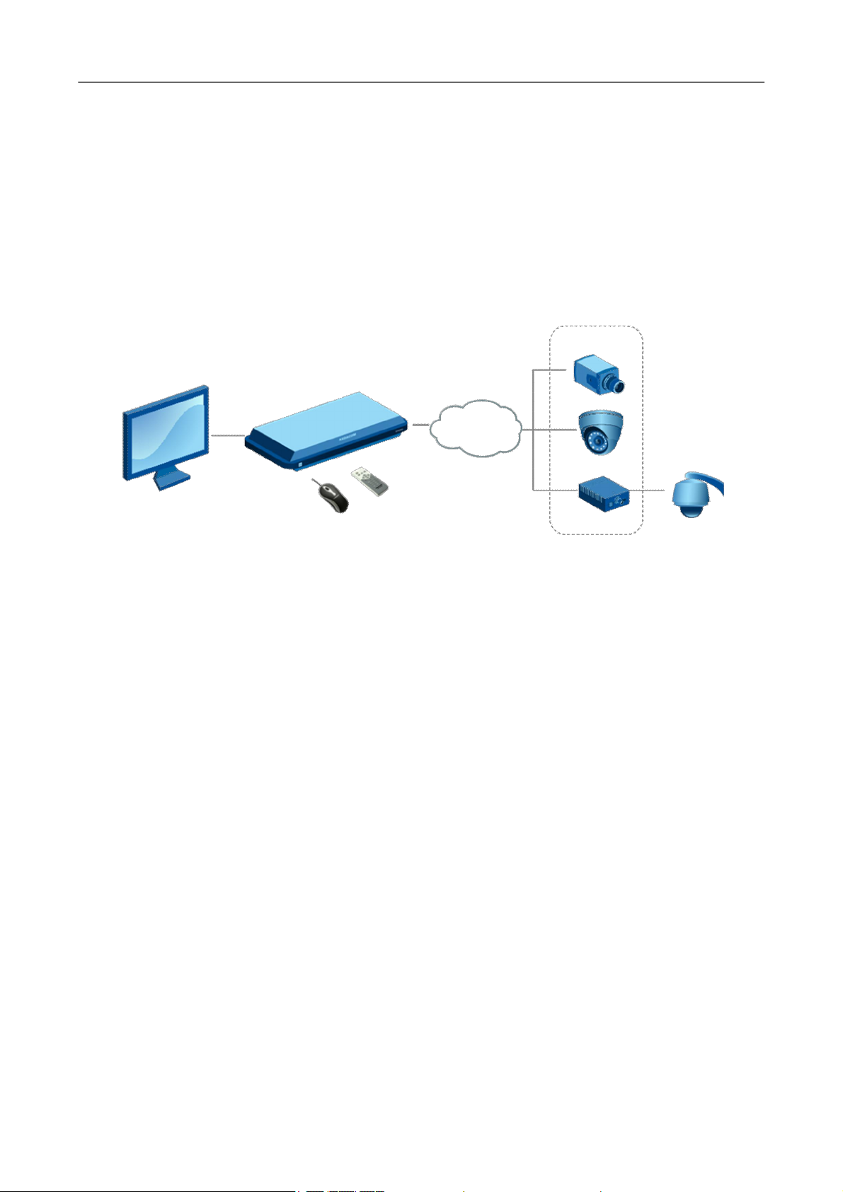
1 Device Description
1.1 NVR Overview
NVR is short for network video recorder.
The NVR is a surveillance host connected to front‐end audio/video acquisition devices and alarm devices
over IP network and providing the functions of browsing, recording, playback, camera control, and
alarming.
NVR
IP network
Front‐end network surveillance devices
The core value of the NVR lies in that it is a type of video middleware compatible with the coding modes
of various digital devices. This provides the advantages of distributed architecture and modular access
over network.
1.2 Functions and Features
Basic functions
l Embedded Linux operating system.
l Real‐time recording for four720P digital video inputs with the NV0402S, or real‐time recording for
eight 720P digital video inputs with the NV0804S.
l One VGA video output, with VGA, CVBS, and HDMI ﴾optional﴿ outputs supported.
l One audio output.
l Synchronous recording and playback in one channel.
l Intercom.
l Built‐in web server for remote control and management.
l Preview on mobile phones ﴾iPhone, Android‐based phones, and BlackBerry﴿.
l Multiple DDNSs supported ﴾Peanut Hull, 3322, and dyndns﴿.
l TB‐level large‐capacity hard disks.
l Digital amplification in local areas by using a mouse.
1

NVRUserManual
l Multi‐level user rights management, ensuring system security.
Storage and backup function
l Two built‐in SATA disk interfaces on the NV0402S and four built‐in SATA disk interfaces on the
NV0804S, supporting TB‐level hard disks.
l Backup based on USB interfaces ﴾such as common USB flash drives and mobile hard disks﴿.
l Download from hard disks over network and backup on a client.
l Non‐working disks in hibernation, facilitating heat dissipation, reducing power consumption, and
extending the service life of hard disks.
l Overwrite cyclic recording and non‐cyclic recording for files on hard disks.
l Dedicated storage format for data, preventing tampering and ensuring data security.
Network function
l One 10M/100M Ethernet interface.
l Parameter setting, real‐time video/audio signal browsing, and NVR status check on web pages
l Control over rotation of the pan tilt zoom ﴾PTZ﴿ and camera parameters ﴾such as the aperture and
focal length﴿ on the web.
l Alarm handling and system logs check.
l Records search and real‐time playback.
l Multi‐level user management, enabling flexible and convenient settings of users and user groups
with different rights.
l Powerful networking functions and multiple networking modes supported.
l Multi‐screen display in remote access over Internet.
Record playback function
l Multiplexing, supporting independent real‐time recording in each channel, multi‐channel search,
and single‐channel playback at the same time.
l Multiple record modes ﴾for example, manual mode and action with alarm﴿ and pre‐recording
function.
l Quick search for record files and classification search based on record types.
l Multiple playback modes, including the slow motion, fast forward, reverse play, and frame‐by‐frame
play modes.
l Display of the accurate event time during the playback of a record.
l Local amplification of any area on the screen during single‐screen and full‐screen playback
l Search for files on a digital video recorder over network during playback.
Real‐time surveillance function
l High‐definition, fine, and soft images on the system screen.
2

NVRUserManual
l Display of channel status ﴾for example, recording and video loss﴿ on the channel screen.
l Single‐screen display, multi‐screen display, and multi‐channel tour.
l Free adjustment of the brightness, contrast, saturation, and tone of preview images.
l Display of the camera name, time, and date on the screen of each digital channel, and free
adjustment of the positions of the preceding items.
l VGA output interfaces, providing the surveillance function with monitors.
l Real‐time display of recording code streams and space occupied per hour.
l Check of local and remote system logs supported.
Voice function
l One audio output.
l Intercom.
l Synchronous audio and video storage in each channel.
l Synchronous audio and record playback.
Alarm function
l One relay alarm output.
l Pre‐recording against alarms, pre‐storing records collected before an alarm is generated, with
configurable pre‐recording time.
l Protective circuits for alarm output interfaces, protecting main devices against damage.
Intelligent operation function
l Operations with a mouse supported.
l Local amplification of any area on the screen during playback.
l Copy and paste of the same settings supported on the menu.
1.3 Hardware Environment
l Power supply: 12V DC.
l Cable connection: Cat 5 network cables and standard AV cables.
l Temperature: Keep the operating temperature within the range from 0ºC to 50ºC. The device may
fail when the temperature exceeds the upper or lower limit. Do not install the device above a heat
source.
l Humidity: Keep the humidity within the range from 10% to 90%. Do not expose the device to rain
or damp environment. Moisture may damage internal components of the device. Do not install the
device close to a water source.
l Ventilation: Install the device in a place with proper ventilation and take dustproof measures.
l Installation mode: Install the device horizontally or in a cabinet. Equip the device with a protective
enclosure in outdoor environment.
3
NVRUserManual
1.4 Software Environment
l Operating system: embedded Linux.
l Firmware: The latest firmware shall conform to that published on the website. Customized firmware
shall conform to the constraints.
1.5 Network Protocols
l Multiple network protocols, including TCP/IP, HTTP, TCP, UDP, ARP, SMTP, FTP, DHCP, DNS, DDNS, NTP,
and UPNP.
l Standard ONVIF protocol.
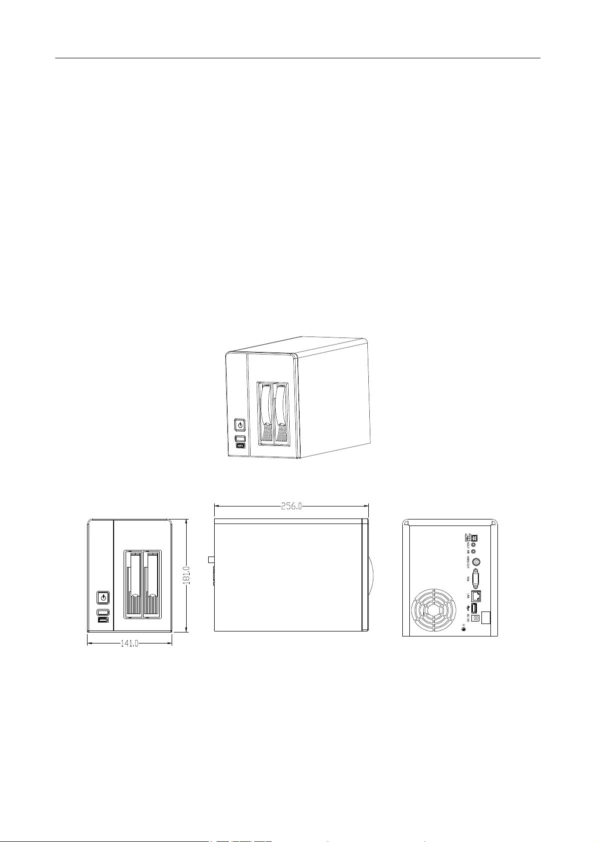
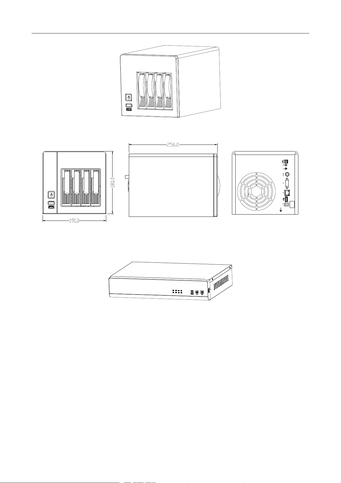
1.6 Appearance
l VSR0402/VSR0804
VSR0402
Front view Side view Rear view
4
NVRUserManual
VSR0804
Front view Side view Rear view
l HVR0402/HVR0804
HVR0402 / HVR0804
5
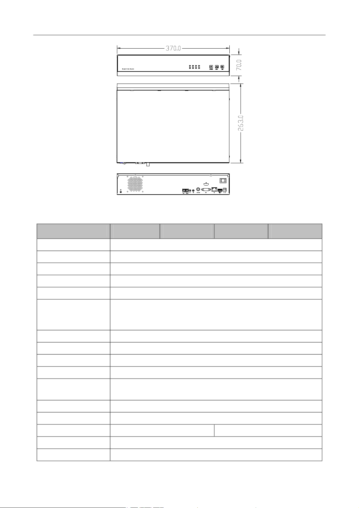
Front view
Top view
Dorsal view
NVRUserManual
1.7 Technical parameters
Model
Main processor Embedded micro‐controller
Operating system Embedded Linux operating system
Simplex/duplex/triplex Pentaplex ﴾recording, playback, backup, network, and preview﴿
Operation method Mouse
Operating language 14 languages, such as Chinese Simplified, English, and Spain
Display/preview
Record resolution Four‐channel recording: 1280 x 720 ﴾720P﴿
Playback resolution Single‐channel playback: 1280 x 720 ﴾720P﴿
Video/audio coding H.264 ﴾video﴿ and G.711 ﴾audio﴿
Record mode Manual, alarm, motion detection, and scheduled
Record search mode
VSR0402 HVR0402 VSR0804 HVR0804
Display/preview resolution of screen 1 ﴾1280 x 720 ﴾720P﴿﴿ and screen 4
﴾704 x 576 ﴾D1﴿﴿
Time‐based search, calendar‐based search, event‐based search, and
channel‐based search
Record storage mode Local hard disks and network
Backup mode Network and USB
High‐definition access Four‐channel, 720P Eight‐channel, 720P
Video output One BNC output and one VGA output ﴾1280 x 1024﴿
HDMI output Optional
6
NVRUserManual
Model
Audio input/output
VSR0402 HVR0402 VSR0804 HVR0804
No input and
one output
2 input and 2
output
No input and
one output
Network interface RJ45 10M/100M adaptive Ethernet interface
485 interface None √ None √
USB interface Two USB 2.0 interfaces
Two SATA interfaces
Four SATA interfaces
Hard disk
Two 2 TB large‐capacity hard disks
Four 2 TB large‐capacity hard disks
Power supply 12 V DC±10% ﴾external power supplies﴿, 3 A
Power consumption < 20 W ﴾without hard disks﴿
Operating temperature 0ºC to 50ºC
Operating humidity 10% to 90%
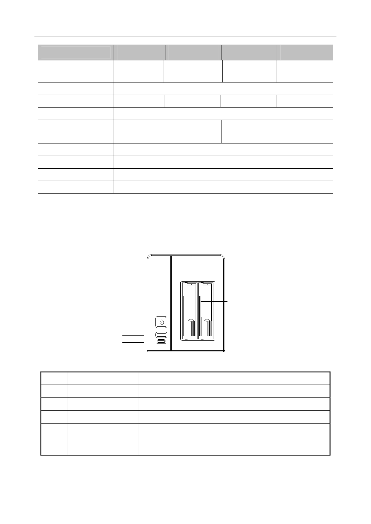
1.8 Panels
1.8.1 Front Panel
2 input and 2
output
l VSR0402/VSR0804
1
2
3
Front panel of the NV0402S
Item Description
1 Power button Used to power on and power off the system
2 Reset button Used to restart the device
3 USB interface Used to connect a mouse
4
4 Disk slot
l HVR0402/HVR0804
Used to hold a hard disk ﴾A screw hole is available on the top of
at the bottom of the slot. You can fix the hard disk by tightening
the screw.﴿
7

NVRUserManual
NVR Series Front Panel Diagram ﴾Take NV0804 as an example﴿
Name/Mark Instruction
j
k
l
m
n
o
p
q
POWER
LINK
REC
1.8.2 Rear Panel
l VSR0402/VSR0804
Video connection indicators: Continuous blue light indicates
successful video connection of corresponding channels.
Power indicator: Continuous blue light indicates the power is
ready.
Network indicator: Continuous blue light indicates the network
is connected.
Hard disk video recording indicator: Continuous blue light
indicates the hard disk is recording.
8
NVRUserManual
10
1
1 2 3 4
5 6 7 8
Rear panel of the NV0402S
Item Description
ALARM
﴾COM, NC, NO﴿
Alarm output interface
COM: common terminal, NC: normally closed, NO: normally open
9
2 AOUT Audio output interface
3 AIN Voice input interface
4 VIDEO OUT CBVS video output interface
5 VGA VGA video output interface
6 LAN RJ45 adaptive Ethernet interface
7 USB interface
8 DC 12V 12 V DC power interface
9 Grounding copper bar
10 Main power switch
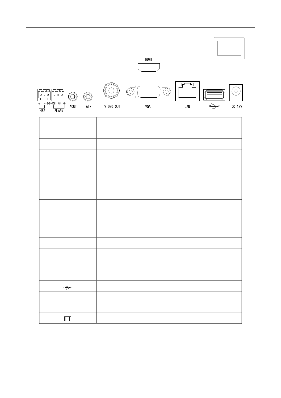
l HVR0402/HVR0804
9
NVRUserManual
Name/Mark Instruction
A1, GND Alarm Input Interface 1
A2, GND Alarm Input Interface 2
﴾485A, 485B﴿ 485 Interface
﴾COM1, NO1, NC1﴿
Alarm Input Interface 1
COM1, NC1 Normal Close, NO1 Normal Open
Alarm Input Interface 2
﴾COM2, NO2, NC2﴿
COM2, NC2 Normal Close, NO2Normal Open
ALARM
﴾COM, NO, NC﴿
Alarm output interface
COM indicates a common port; NC indicates being normally
closed, and NO indicates being normally open.
AOUT Audio output interface
AIN Audio input interface
VIDEO OUT CBVS video output interface
VGA VGA video output interface
LAN RJ45 auto negotiation Ethernet port
USB interface
DC 12V DC12V power interface
HDMI HD video output interface
Main power switch
1.9 Mouse Functions
*This document assumes that you operate the mouse with your right hand.
To perform operations on menus by using a mouse, connect the mouse to the USB interface of the
10

device.
NVRUserManual
Description of mouse functions
When you have not logged in to the system, a password text box is displayed after
you click on the screen.
A menu is displayed when you click a menu icon.
This action allows you to perform operations instructed on the controls.
This action allows you to change the status of a checkbox or a motion detection
area.
Click
Double‐click
Right‐click
A drop‐down list is displayed when you click a combo box.
In a text box, you can select an input method, for example, numeric input, character
input, uppercase/lowercase English letter input, or Chinese input. You can type a
character by clicking it on the panel. ← indicates a backspace, and _ indicates a
space. In an edit box, ← indicates the input of a space, and _ indicates the deletion
of the character before the cursor. In a numeric box, ← indicates zeroing out, and _
indicates the deletion of the last digit. You can type only digits ﴾for example, the
standby time in common setting﴿ in a numeric box. You can type any characters ﴾for
example, a channel name﴿ in an edit box.
This action allows you to perform special operations of controls. For example, you
can double‐click an option in a record file list to play back the record.
In multi‐screen mode, when you double‐click a specific screen, the screen is
displayed in full‐screen mode. When you double‐click the screen again, it returns to
the multi‐screen mode.
When you right‐click the screen during real‐time surveillance, a shortcut menu is
displayed, providing the multi‐screen mode, image color, record search, manual
recording, alarm input, alarm output, and main menu options. The multi‐screen
mode is relevant with the number of channels on the device. For example, a
four‐channel device displays only a single screen or four screens. The image color
applies to the channel that the cursor indicates. In multi‐screen mode, the system
automatically switches to the single screen of the corresponding channel before
the setting of the color image.
Scroll
Move
Drag
This action allows you to exit the current menu without saving the settings.
This action allows you to increase or decrease the number in a numeric box.
This action allows you to switch between options in a combo box.
This action allows you to page up and page down in a list box.
You can select a control or a component of a control in the current coordinates and
move it by using the mouse.
This action allows you to select motion detection areas, area settings, and area
coverage.
11

NVRUserManual
JNote: If a mouse cannot be detected after you connect it to the NVR, the mouse is incompatible
with the NVR. Replace the mouse.
1.10 Input Methods
In a text box, you can select an input method, for example, digit input, character input,
uppercase/lowercase English letter input, or Chinese input. You can type a character by clicking it on the
panel.
Icon Description Icon Description
Lowercase English letter input status Numeric input status
Uppercase English letter input status Chinese ﴾full spelling﴿ input status
Deletion key: to delete the character
before the cursor
Special character input status
Space key
12

NVRUserManual
2 Installation and Cable Connection
Note the following during the installation:
1. Take out all materials required for the installation.
2. Connect cables ﴾video signal input cables, audio signal input cables, and network cables﴿ as
required.
3. Connect the rear panel, front panel, and power supply in sequence.
4. Take out the regulated power adapter or power cable and connect the power supply.
2.1 Hardware Installation
Check After Unpacking
l After you receive the product, check the appearance to see whether it is damaged during the
transportation.
l Open the packing box and check the accessories according to the packing list.
l Remove the protective film from the product.
Front Panel and Rear Panel
l Read the descriptions of buttons on the front panel and interfaces on the rear panel in the
instruction.
l Check the model on the protective film of the front panel against the order contract.
l Keep the label on the rear panel intact. It is required for after‐sales services. Do not tear down or
discard the label. Otherwise, no warranty service will be provided. When you call after‐sales
personnel of the company, provide the serial number of the product.
Internal Check
Check for damage and scratches. Check whether data cables, power cables, and fan power supplies are
connected to the main board on the front panel properly.
Precautions ﴾Contact us if you have any doubt﴿
1. After unpacking, ensure that the materials are consistent with the packing list.
2. Check the voltage, avoiding device damage caused by improper voltage.
3. Check the installation environment. Do not use the device in damp or high‐temperature environment.
Ensure proper ventilation and keep the air vents unblocked. Lay the device horizontally. Do not install
the device in environment with sharp vibration.
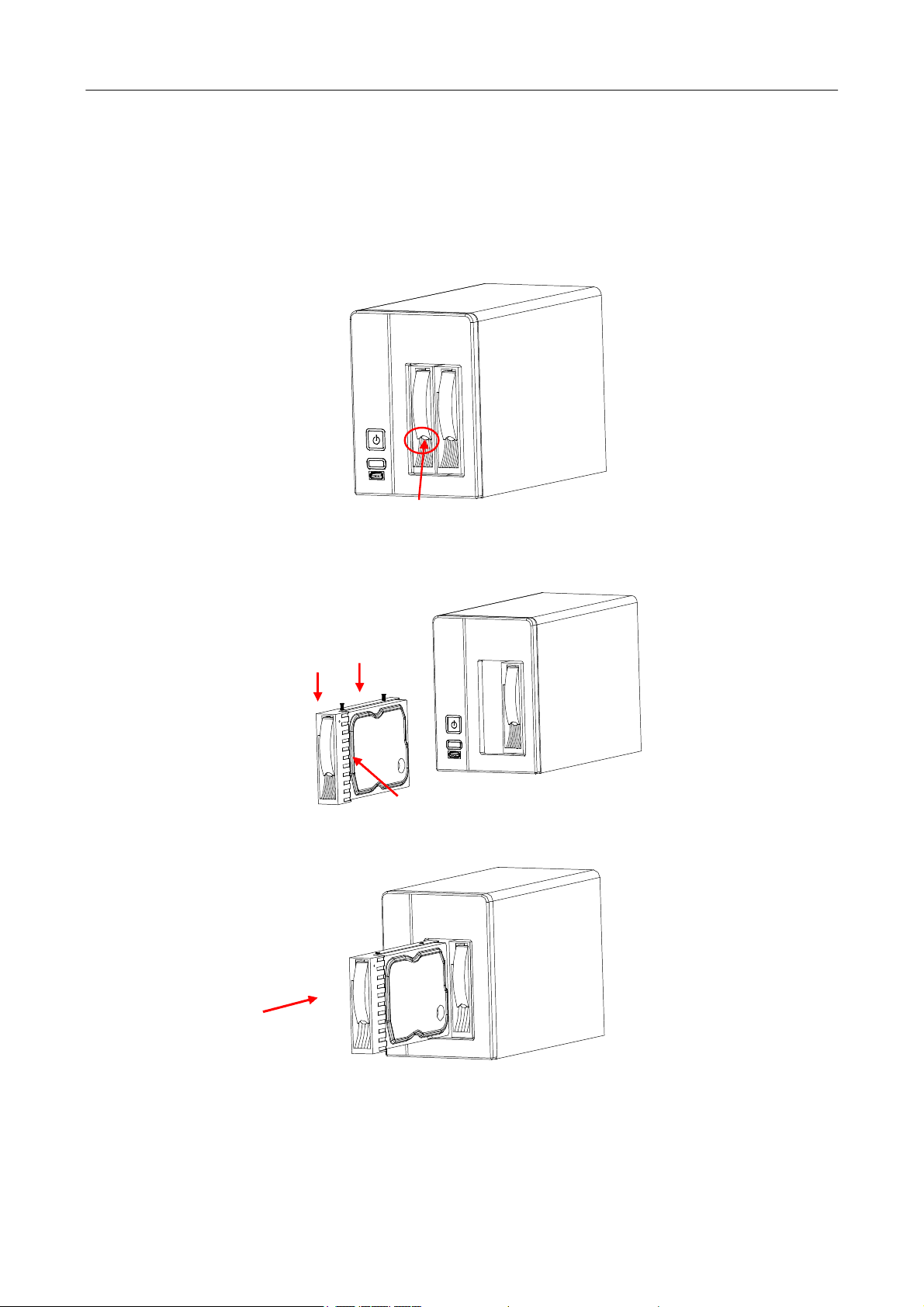
2.2 Hard Disk Installation
Check whether hard disks are installed when you install the device for the first time. The NVR supports
13
NVRUserManual
TB‐level hard disks. Use recommended models of hard disks ﴾7200 rpm or above high‐speed hard disks﴿
and SATA disk cables delivered with the device.
l VSR0402/VSR0804
To install a hard disk on the VSR0402, perform the following operations:
1. Press the button at the bottom of a disk slot to eject the disk slot.
2. Pull the disk slot out of the shelf, install a hard disk in the disk slot, and fix the hard disk using two
screws.
3. Insert the disk slot in the shelf. If a sound is generated, the disk slot is inserted properly.
l HVR0402/HVR0804
14
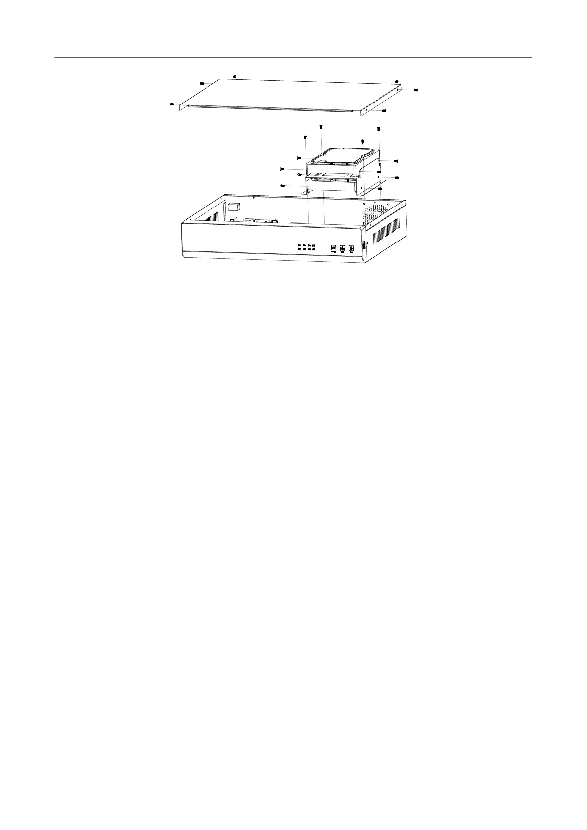
NVRUserManual
1. Unscrew the screws, and remove the cover.
2. Unscrew the hard disk slot screws, and take out the hard disk slot from the chassis.
3. Put a hard disk in the hard disk slot and fix the hard disk into the hard disk slot with screws.
4. Install the hard disk slot into the chassis, and fix it with screws.
5. Install the cover, and fix it with screws.
2.3 Device Installation
Procedure and precautions:
1. Lay the device on a flat and stable rack.
2. Ensure that the temperature in the room is below 35ºC ﴾95ºF﴿.
3. Leave a 15 cm ﴾6 in.﴿ space around the device for air circulation.
4. Install assemblies on the rack from bottom to top.
5. When multiple assemblies are installed on the rack, take proper measures to avoid overload of the
power socket on the rack.
2.4 Video Input and Output Connections
Video input connections ﴾LAN﴿
l Connect network cameras to the NVR. If only one network camera is available, connect it to the NVR
directly through a network cable. If multiple network cameras are available, connect them to the
NVR through a switch.
Video output connections ﴾VGA, VIDEO OUT, HDMI﴿
l The NVR supports VGA and CVBS video outputs. You can use both output modes or use one of
them.
l Dedicated monitors, computer displays, televisions, video matrixes, and high‐definition large‐screen
15
 Loading...