

Vidatronic TVT-20, TVR-20 Installation Instruction And Product Specifications

2800-00009
1
Twisted pair video transmitter TVT-20 and video receiver TVR-20
Installation instruction and product specifications
PREFACE
The video transmitter TVT-20 and receiver TVR-20 is our middle to long distance transmission set. They are selfcontained with power supply for 230VAC mains supply. The series perform easy installation and transmission of black &
white and colour signals through CAT5E twisted pair cable, as well as standard 0.6mm UTP cable. The product series is
been developed based upon the idea – “to establish a very good transmission quality for an acceptable price”.
TVT-20
Video output amplitude is selectable by means of a jumper (J4), performing from 2Vpp flat to 4Vpp with up to 9dB preemphasis @ 5MHz. The output impedance is =/< 110 Ohms +/- 20%, matching CAT5E and standard 0.6mm UTP.
TVR-20
The receiver has galvanic separation. Line input impedance is selectable for CAT5E and standard 0.6mm UTP by means
of a jumper (J4). The receiver is having only three adjustments, GAIN (RV1), SIGNAL (RV2) and LF (RV3).
The output driver is of the “CF” type having a very effective dc-restoration, having great importance for colour signals.
Green LED (DS1) indicates when sync signal is present (flashing with 25 Hz).
KEY FIGURES
- Easy to install (mounting kit for wall mounting included)
- Easy to adjust
- Compact construction in a IP65 PC enclosure
- Transmission distance up to max. 1.500 meters at CAT5E (1.700-1.800 meters at 0.6 UTP, ref. to the
specifications).
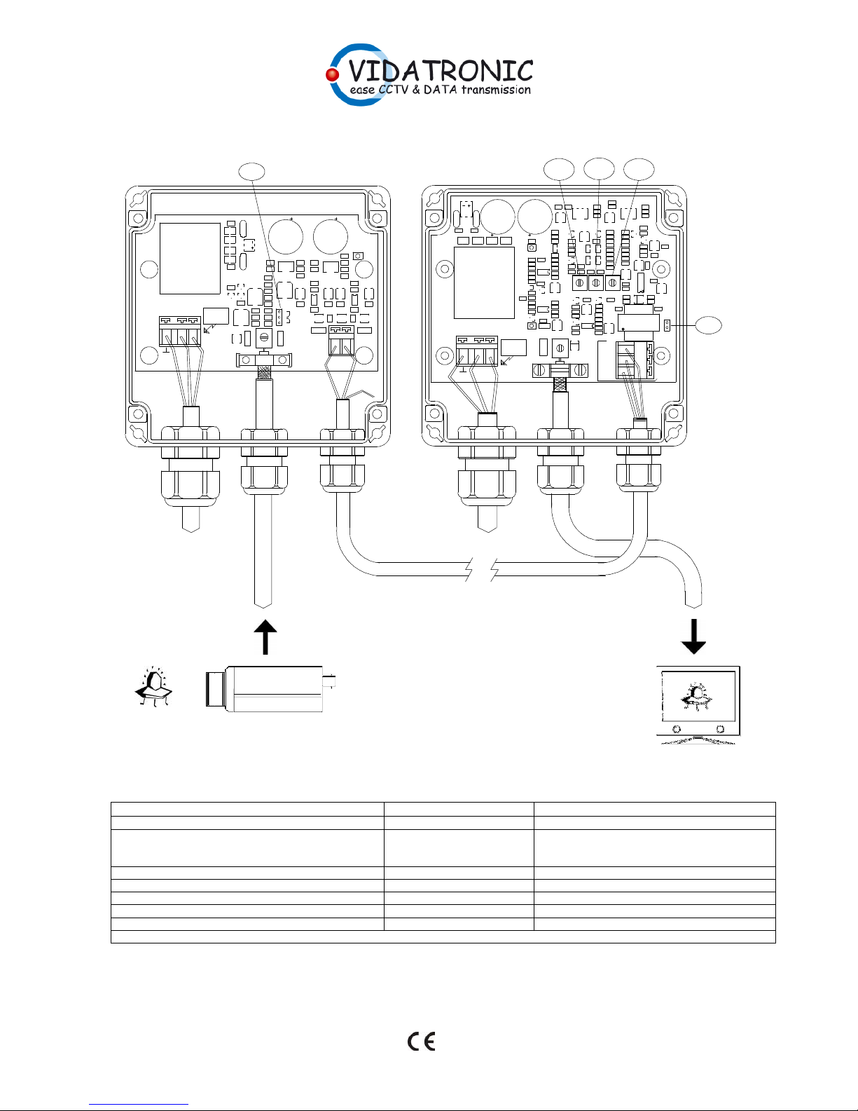
INSTALLATION (ref. to the figure at page 2)
1) Install the receiver on a flat surface (wall of wood, bricks or like) with the enclosed mounting kit.
2) Connect the twisted pair cable to J2 at the transmitter and to J1 at the receiver, by “colour-to-colour”.
OBS: A possible shield at the cable may ONLY be connected to the receiver ground – not at the transmitter.
3) Connect the camera coax cable to J1 at the transmitter and the monitor or system cable to J2 at the receiver.
Make sure to perform the connection in a secure way.
4) Connect the mains cable by Green/Yellow to Earth, Blue to “N” and Brown to “L”. The power cable must be
connected to the mains power through a two pole mains switch. The earth wire must be connected to a
ground connection in a secure way in order to maintain the EMI/EMC safety for the products.
5) Set the jumper J4 at the transmitter to the position adequate for the distance which has to be transmitted.
Guideline when using CAT5E cable;
1) At distances up to about 500 meter, leave the jumper OPEN.
2) At distance up to 1.000 meter, set the jumper in position “1-2”. (3Vpp + pre-emphasis)
3) At bad cable installations or distances above 1.000 meter (above the data limit) set the jumper in
position “2-3” (4Vpp + pre-emphasis)
6) With a signal pattern generator connected to the transmitter, adjust RV1 (Gain), RV2 (Signal) and RV3 (LF) at
the receiver until you have a clean picture with the right colour balance and contrast. Fine adjust eventually
the signal output amplitude from the receiver by means of RV1.
7) Replace the pattern generator with the actual camera for that position and eventually perform a fine adjust.
NOTE: Make sure that the cable glands have been tightened well and that all ¼ turns lock screws at
the lid has been locked correctly in order to maintain the IP 65 grade.
2800-00009
2
230
VAC Mains I
n
230VAC Mains In
up to 1.500 meters
(ref. to the specifications for more detailed information)
NC
TVT-20
TVR-20
RV3
RV2
RV1
J4
J4
U1
U2
Q3
Q2Q1
D5
C23 C22
J1
T1
L2
L3
C25
L4
FL2
FL1
C24
L1
C3
C10
R7
C13
R19
C18
R20
R21
C16
C19
R18
R9
R15
C4
C12C2C9
C6
C20
C21
U4
R3
C15
C1
R1
R2
R4
R17
R16
R6
J4
R25
R26
D1
J3
C7
R5
C8
C14
R8
R11
D2 R12
R10
C11
C5
R22
C17
R23
U3
D3
R28
R27
J2
R24
D4
DS1
ac ac
--------------- ACHTUNG
DANGER
3Vpp
4Vpp
1
2
3
OPEN:
2Vpp
IN
VIDEO
OUT
BAS
MAINS IN
N L
VTR_0499-00009 v.2
V
B
V
T
-
2
0
PWR
- +
C52
C47
C48
L4L3
DS2
R16
L1
C21
FL1
D3
FL2
C20
L2
T1
DS1
Q1
R10
R1
R3
U2
R2
C46
J1
C28
C7
C9
R14
R15
C23
U5
R49
R35
C34
RV2
R17
VT1
J4
R54
D2
U1
C11
Q9
R31
R51
C51
R56
R52
R23 R55
Q7
R25
R30 R28
Q4
C6
RV1
R22
CR3
C39
R50
C41
R36
R33
C43
R53
C5
C26
C25
R13
R12
C19
U4
C22C24
C4
R32
C31
Q8
R26
C29
C30
R27
R48
C50
C49
C40
RV3
R29
Q5
R60
Q6
R24
C44
Q10
CR2
U6
Q3
D4
R46
C36
R40
C33
R41
R39
C37
CR1
CR4 CR5
C45
R34
C32
R59
R44
R43
C38
C8
C16
C15
C12
C3
U3
C1
C13
R4
C18
C17
C2
C14
R5
Q2
R9
R8
D1
J2
J3
C53
C10
C54
C55
IN
VIDEO
GND
SYNC
acac
PWR
--------
ACHTUNG
DANGER
MAINS IN
N L
VIDATRONIC 0499-00021 v.0
VBVR-20
VIDEO
BAS+
BAS-
OUT
IMP.
R57
C35
R11
R7
R6
R18
R19
R20
R21
C27
R47
R42
R45
C42
R58
R38
R37
SPECIFICATIONS, TVT-20
Description
Value
Note
Video input unbalanced (by coax screw terminal) 1 Vpp 75 Ohms
Video output balanced @ 1Vpp in (by Wago spring
terminals)
2 Vpp
3 Vpp + 6dB @ 5Mhz
4 Vpp + 9 dB @ 5Mhz
J4 Open
J4 in pos. 1-2
J4 in pos. 2-3
Line output impedance 110 Ohms +/- 20%
Temperature range -20 / +45 Degree Celsius @ 85% RH
Mains supply (by Wago spring terminals) 230 VAC +/- 10% 45-60 Hz
Current consumption Max. 25 mA @ 230 VAC
Weight 425 g.
ADJUSTMENTS: J4 Gain and Pre-emphasis - S1 output line impedance
 Loading...