

VIDAR NDTPRO, AdvantagePRO Series, DosimetryPRO Advantage, DiagnosticPRO Advantage, CAD PRO Advantage Installation Manual
Page 1
VIDAR NDTPRO
Industrial Film Digitizer
Installation Guide
For Use with Windows 7, 8, & 10
(Serial Numbers 370,000 to 379,999)
Page 2
© Copyright November 2019 by VIDAR Systems Corporation. All rights reserved.
365 Herndon Parkway
Herndon, VA 20170 U.S.A.
Phone: 1-703-471-7070
Fax: 1-703-471-7665
Internet: www.vidar.com
Emergo Europe
Prinsessegracht 20
2514 AP, The Hague
The Netherlands
Sales: 1-800-471-7070 or
1-800-471-7226
Email: [email protected]
Technical Support:
1-800-471-7070 or 1-703-471-7070
E-mail: [email protected]
E-mail: [email protected]
19440-001 Rev. E VIDAR NDTPRO Industrial Film Digitizer Installation Guide 2
Page 3

Caution: No operator-serviceable parts inside. Refer servicing to qualified personnel.
Achtung: Gehäuse nicht öffnen. Wartung uno reparatur nur durch eletrofachkräfte.
Attention: Aucune piece ne peut etre remplacee par l’utilisateur. Toute operation de
maintenance doit etre effectuee par une personne qualiee.
Atencion: Acceso interno solo autorizado a personal tecnico cualificado.
Attenzione: Non appire. Rivolgersi a personale qualificado.
Radio Frequency Emissions
This equipment has been tested and found to comply with the limits for a Class A digital
device, pursuant to Part 15 of the FCC Rules. These limits are designed to provide
reasonable protection against harmful interference when the equipment is operated in a
commercial environment. This equipment generates, uses, and can radiate radio
frequency energy and, if not installed and used in accordance with the instruction manual,
may cause harmful interference to radio communications. Operation of this equipment in
a residential area can cause harmful interference, in which case the user will be required
to correct the interference at his or her own expense.
Product compliance testing was conducted using VIDAR shielded cables. Modifications
to the digitizer or the VIDAR shielded cables or the use of cables other than those
available from VIDAR could void the user’s authority to operate the equipment.
Acceptable shipping conditions
Temperature: –18° to +60°C (0° to +140°F)
Relative humidity: 20% to 85%, non-condensing
Atmospheric pressure: 500 to 106 hPa (+18,000 to –1,200ft)
Operating conditions
Temperature: 10°C to 30°C (60°F to 85°F)
Relative humidity: 20% to 85%, non-condensing
Atmospheric pressure: 696 to 1013hPa (10,000 to 0 ft)
Electrical supply
Voltage: 100 to 240 VAC
Current: 0.75 to 1.5 A
Frequency: 47 to 63 Hz
19440-001 Rev. E VIDAR NDTPRO Industrial Film Digitizer Installation Guide 3
Page 4
Safety and compliance information
MEDICAL –GENERAL MEDICAL EQUIPMENT AS TO ELECTRIC SHOCK, FIRE
AND MECHANICAL HAZARDS ONLY IN ACCORDANCE WITH: CSA CAN/CSAC22.2 NO. 60601-1:14, IEC 60601-1:2005+A1:2012) Edition 3.1. ANSI/AAMI
ES60601-1: A1:2012, C1:2009/(R)2012 and A2:2010/(R)2012.
Accessory equipment connected to the analog and digital interfaces must be certified
5RA9
This product is rated for continuous use.
This product is in the Ordinary Equipment Class. It provides no protection against the ingress of water.
This product is not suitable for use in the presence of flammable anesthetic mixtures with air or with oxygen or
with nitrous oxide.
according to the respective IEC standards (i.e. IEC 60950 for data processing equipment
and IEC 60601-1 for medical equipment). Furthermore all configurations shall comply
with the system standard IEC 60601-1-1 or IEC 60601-1 Edition 3.1.
Everybody who connects additional equipment to the signal input part or signal output
part configures a medical system, and is therefore responsible that the system complies
with the requirements of IEC 60606-1-1 or IEC 60601-1 Edition 3.1. If in doubt, consult
the technical services department or your local representative.
Class I Medical Device; No Applied Parts. This product provides Class I medical device protection against
electrical shock.
WARNING: To avoid the risk of electric shock, this equipment must only be connected to a supply mains with
protective earth.
Grounding reliability can only be achieved when the equipment is connected to an equivalent receptacle marked
“HOSPITAL ONLY” or “HOSPITAL GRADE”.
WARNING: Do not modify this equipment without authorization of the manufacturer.
Do not position the product so that it is difficult to access the disconnect switch (power switch) on the back of the
unit.
Mains power may be removed from the product by turning off the power switch on the back of the unit.
Power cords used with this device in North America must be rated by Underwriters Laboratories for hospital use.
Power cords used with this device in Europe must meet the requirements of IEC 227 Designation 53 or IEC 245
Designation 53.
Correct and safe operation of the digitizer requires familiarity with information
that is not marked on the product. The following symbols indicate that the
operator should consult the manual for additional information:
This Class 1 LED device is safe under reasonably foreseeable conditions of
operation.
The LED illumination system consists of 16 Class 1 LEDs, a mirror system to
spread the light, and a diffuser to distribute the light approximately uniformly
across an area of 2.4 sq. in (15.5 sq. cm). Light from the LED illuminator may be
indirectly observed in the digitizer’s film entry and exit areas.
19440-001 Rev. E VIDAR NDTPRO Industrial Film Digitizer Installation Guide 4
Page 5

Table of Contents
Intended Use ............................................................................................................................. 6
Unpack ....................................................................................................................................... 7
1. Look for Damage ...................................................................................................... 7
2. Unpack the shipping carton ..................................................................................... 8
3. Unpack the Accessory Box ....................................................................................... 9
4. Unwrap .................................................................................................................... 10
5. Identify the Components ......................................................................................... 11
6. If Anything Is Missing... ........................................................................................... 12
7. Activate Your Product Warranty.............................................................................. 12
Setting Up ................................................................................................................................ 13
1. Identify Important Features .................................................................................... 14
2. Assemble the Digitizer ........................................................................................... 15
3. Connect the Power Cord ........................................................................................ 20
Device Driver Installation ....................................................................................................... 21
Install Device Drivers for Windows 7, 8, and 10 ........................................................... 21
1. Apply Power to the Digitizer .................................................................................... 21
2. About the VIDAR Drivers ........................................................................................ 22
3. Install the VIDAR Drivers ........................................................................................ 22
Appendix: Electromagnetic Guidance ................................................................................. 29
Appendix: Symbols ............................................................................................................... 33
19440-001 Rev. E VIDAR NDTPRO Industrial Film Digitizer Installation Guide 5
Page 6

Intended Use
The NDTPRO Industrial Film Digitizer is intended for making digital copies of x-ray films for nondestructive testing applications. This device is not intended for medical use.
19440-001 Rev. E VIDAR NDTPRO Industrial Film Digitizer Installation Guide 6
Page 7

In this chapter, you will:
Unpack and inspect the digitizer’s parts.
Identify the digitizer’s parts.
1. Look for Damage
Before unpacking the Digitizer, examine the shipping carton for damage.
If the carton is damaged:
Notify the shipper immediately.
Take photographs of the damage.
Send pictures and description of damage to: [email protected].
Notify VIDAR Support at 1-703-471-7070.
Unpack
19440-001 Rev. E VIDAR NDTPRO Industrial Film Digitizer Installation Guide 7
Page 8
2. Unpack the shipping carton
IMPORTANT: Save all the packing materials. If you need to
ship the digitizer later, you should repack the digitizer in the
original materials by reversing the procedure described here.
Failure to properly pack, or failure to use VIDAR authorized
shipping materials, will void the product’s warranty, and will
likely result in costly repairs.
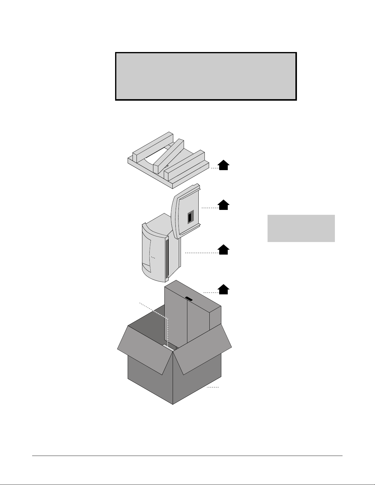
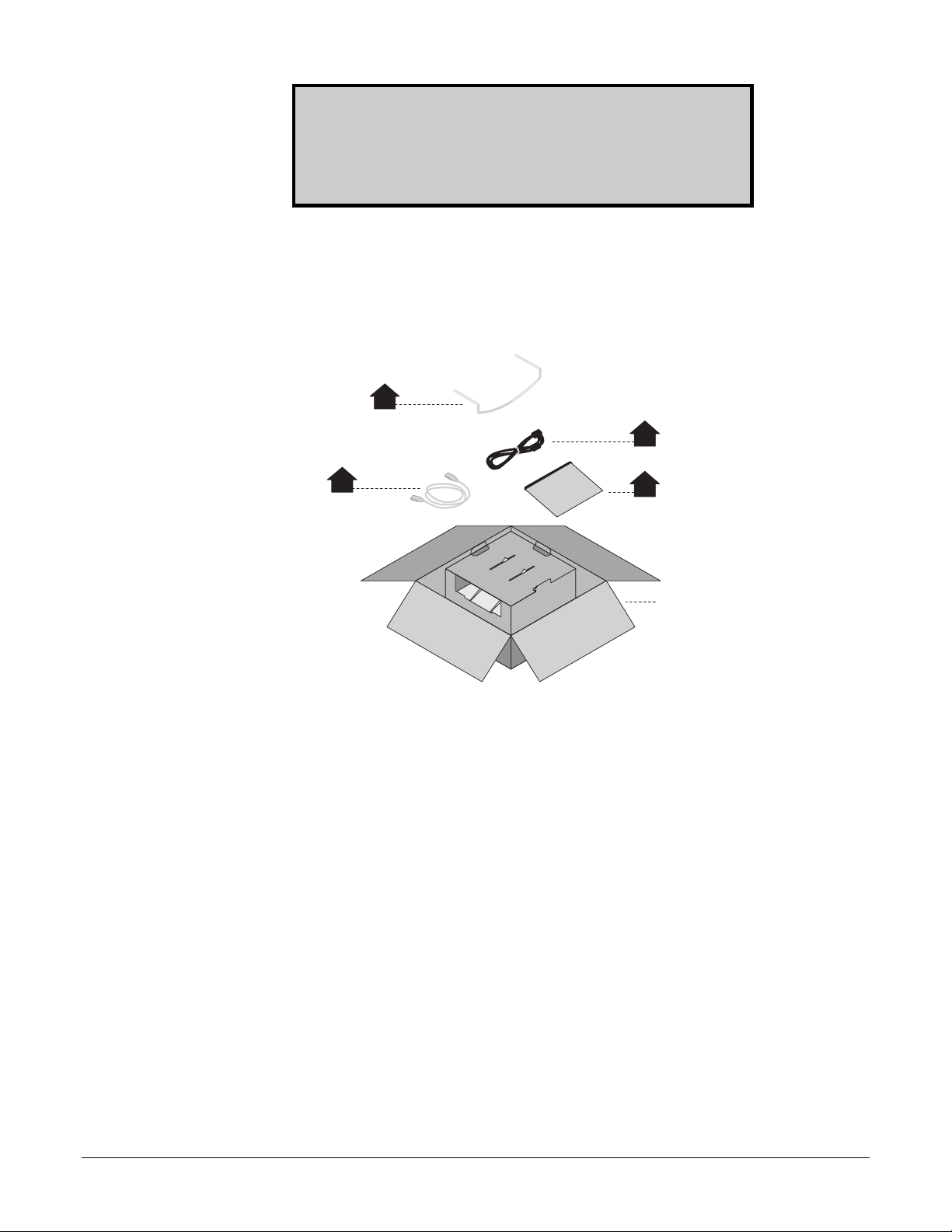
Remove items from the shipping carton in the order shown below.
1
Upper foam support
Leave in box:
lower foam support
2
Feeder
Note: For clarity, this
illustration does not show
the plastic bags surrounding
the digitizer and feeder.
3
Digitizer base
4
Accessory box
Shipping carton
19440-001 Rev. E VIDAR NDTPRO Industrial Film Digitizer Installation Guide 8
Page 9
IMPORTANT: Save all the packing materials. If you need to
ship the digitizer later, you should repack the digitizer in the
original materials by reversing the procedure described here.
Failure to properly pack, or failure to use VIDAR authorized
shipping materials, will void the product’s warranty, and will
likely result in costly repairs.
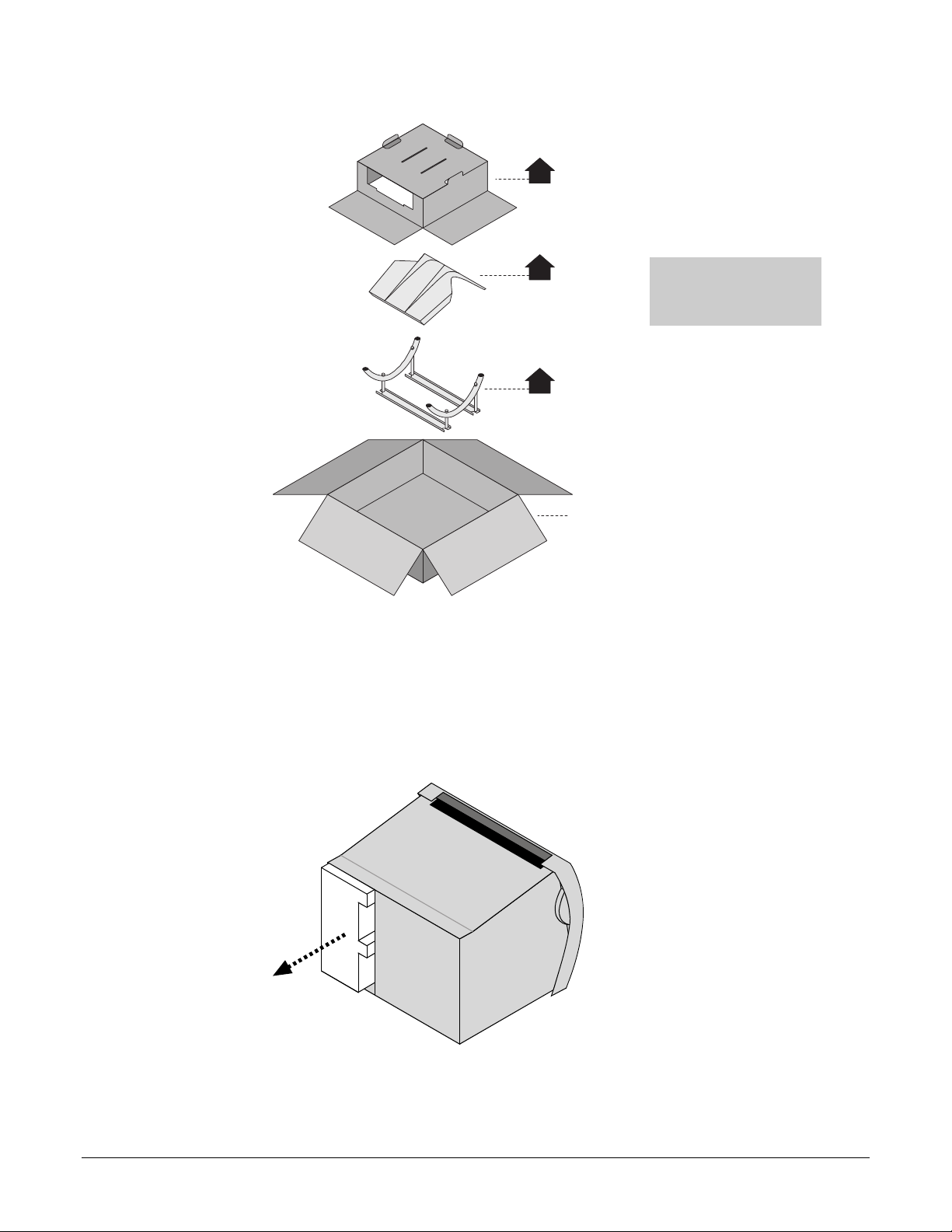
3. Unpack the Accessory Box
a. Remove these items from the accessory box:
2
Film support bar
in padded bag
(bag not shown)
3
Power cord
1
USB cable
4
Documentation in
padded bag (bag
not shown)
Accessory box
19440-001 Rev. E VIDAR NDTPRO Industrial Film Digitizer Installation Guide 9
Page 10
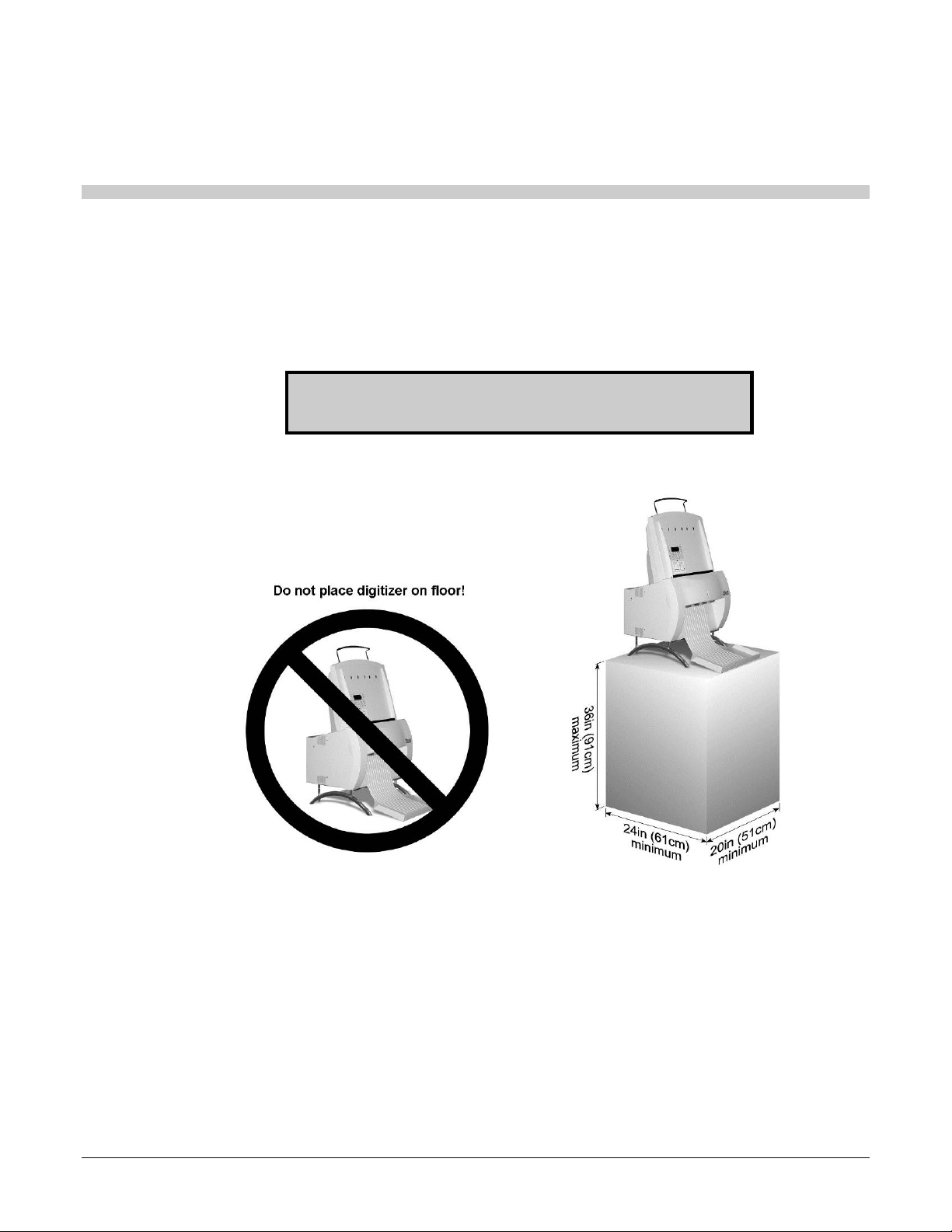
b. Then remove these items from the accessory box:
5
Cardboard retainer
4. Unwrap
6
Exit tray
7
Stand
Accessory box
Note: For clarity, this
illustration does not show
the plastic bag surrounding
the exit tray.
a. Unwrap all items.
b. Remove the foam block from the rear of the digitizer base:
19440-001 Rev. E VIDAR NDTPRO Industrial Film Digitizer Installation Guide 10
Page 11

IMPORTANT: Save the carton and all packing materials. If
you need to ship the digitizer later, you must repack it using the
original wire ties, plastic bags, foam supports and cartons.
Instructions for repacking are provided in the “Packing the film
digitizer for shipment” section of this manual.
5. Identify the Components
Item
Digitizer base
Exit tray
Film feeder
Film support bar
Stand
Power cord: 115V (p/n 4043-001) or 230V (p/n 2104-006)
Quick setup card
USB cable: 6 foot (p/n 4618)
VIDAR NDTPRO Industrial Film Digitizer CD
Digitizer Base
Film Support bar
Exit Tray
Stand
Film Feeder
19440-001 Rev. E VIDAR NDTPRO Industrial Film Digitizer Installation Guide 11
Page 12

6. If Anything Is Missing...
Immediately contact your VIDAR supplier.
7. Activate Your Product Warranty
a. Locate the “Warranty information card” form on the NDTPRO Industrial Film
Digitizer CD.
b. Print the “Warranty information card.”
c. In the “Product information” section, record this information:
Digitizer serial number.
d. Complete the form.
e. Mail or fax the form to VIDAR Systems Corp.
If your digitizer needs service, this information should be on file at VIDAR.
Contact VIDAR Technical Support if you have any questions
about installing or using your VIDAR film digitizer:
Phone: +1.800.471.SCAN (+1.800.471.7226)
+1.703.471.7070 outside the U.S.
E-mail: [email protected]
NEXT: Go to “Setting up”
19440-001 Rev. E VIDAR NDTPRO Industrial Film Digitizer Installation Guide 12
Page 13
Setting Up
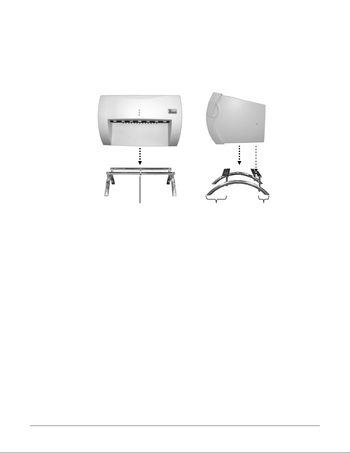
The digitizer must be placed on a counter or tabletop.
SAFETY WARNING
Never place the digitizer on the floor.
19440-001 Rev. E VIDAR NDTPRO Industrial Film Digitizer Installation Guide 13
Page 14

1. Identify Important Features
y
Look over the digitizer base and locate the features shown in this section. You will need
to know where these features are when you assemble the digitizer.
Film Feeder Screw holes
Film Feeder
Connector
Digitizer base, rear view
Kernel
Switch—
Factor
USB Port
ON/OFF Switch
Power Entry module
use
ON/OFF switch
(a rocker switch)
Press I to turn power ON.
Press 0 to turn power OFF.
Power switch and power entry module
19440-001 Rev. E VIDAR NDTPRO Industrial Film Digitizer Installation Guide 14
Page 15
2. Assemble the Digitizer
1. Place the stand on a solid, flat surface (such as a table).
2. Place the digitizer base on the stand as shown below. Tighten the thumbscrews on the
bottom of the stand to secure it to the digitizer.
Front view Side view
Front
*
Thumbscrews (2) Longer portion toward front
*Vent in bottom of base
must be over cutout in stand
19440-001 Rev. E VIDAR NDTPRO Industrial Film Digitizer Installation Guide 15
Page 16
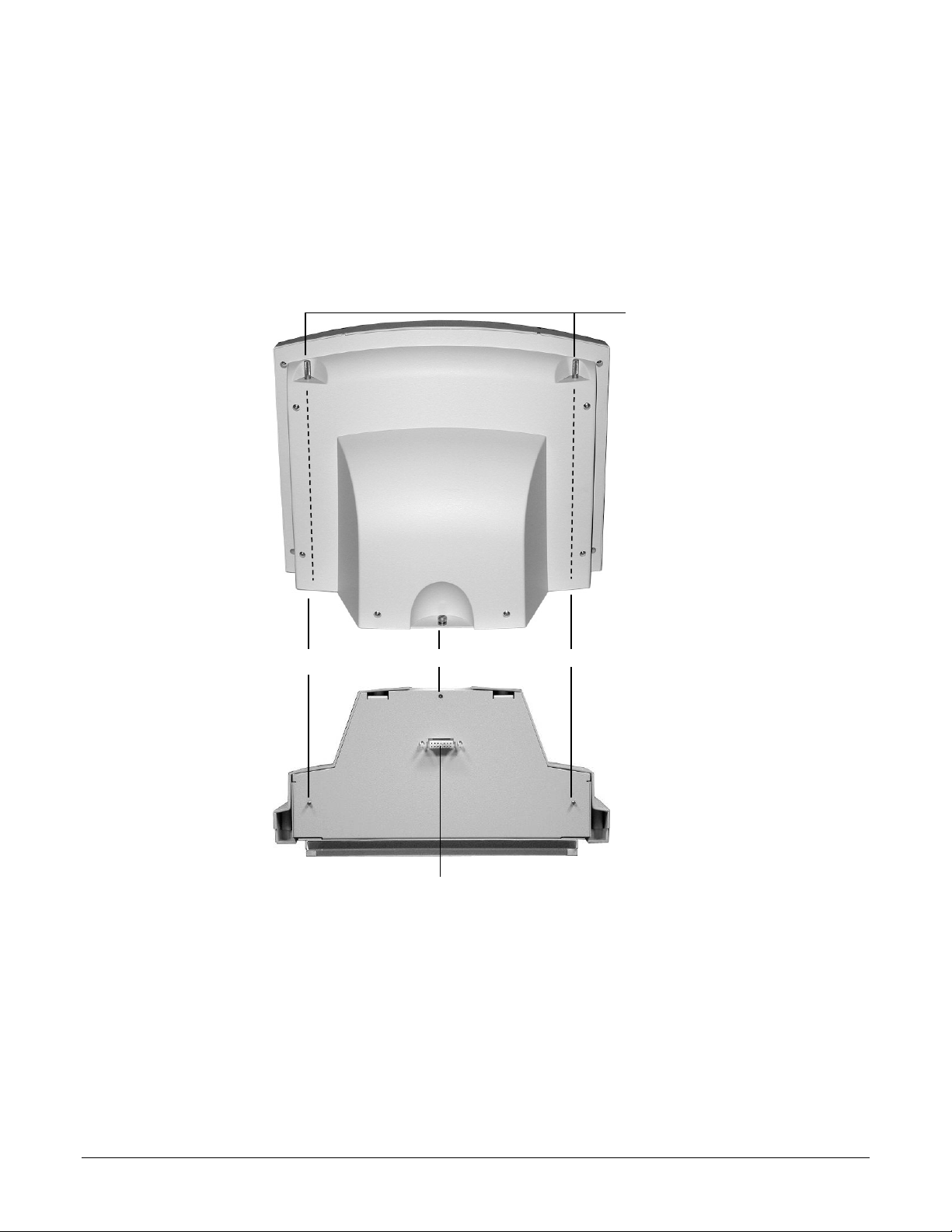
3. Attach the feeder to the digitizer:
a. Note the three screws protruding from the bottom of the feeder. These mate to
holes in the digitizer base. Two of the screws are very long—their tops ends are
near the top of the feeder.
Also note the connector on the bottom of the feeder. It mates to the connector on
top of the digitizer base.
Top ends of
long screws
Feeder, rear view
Long screw Short screw Long screw
Connector
Feeder, bottom view
19440-001 Rev. E VIDAR NDTPRO Industrial Film Digitizer Installation Guide 16
Page 17
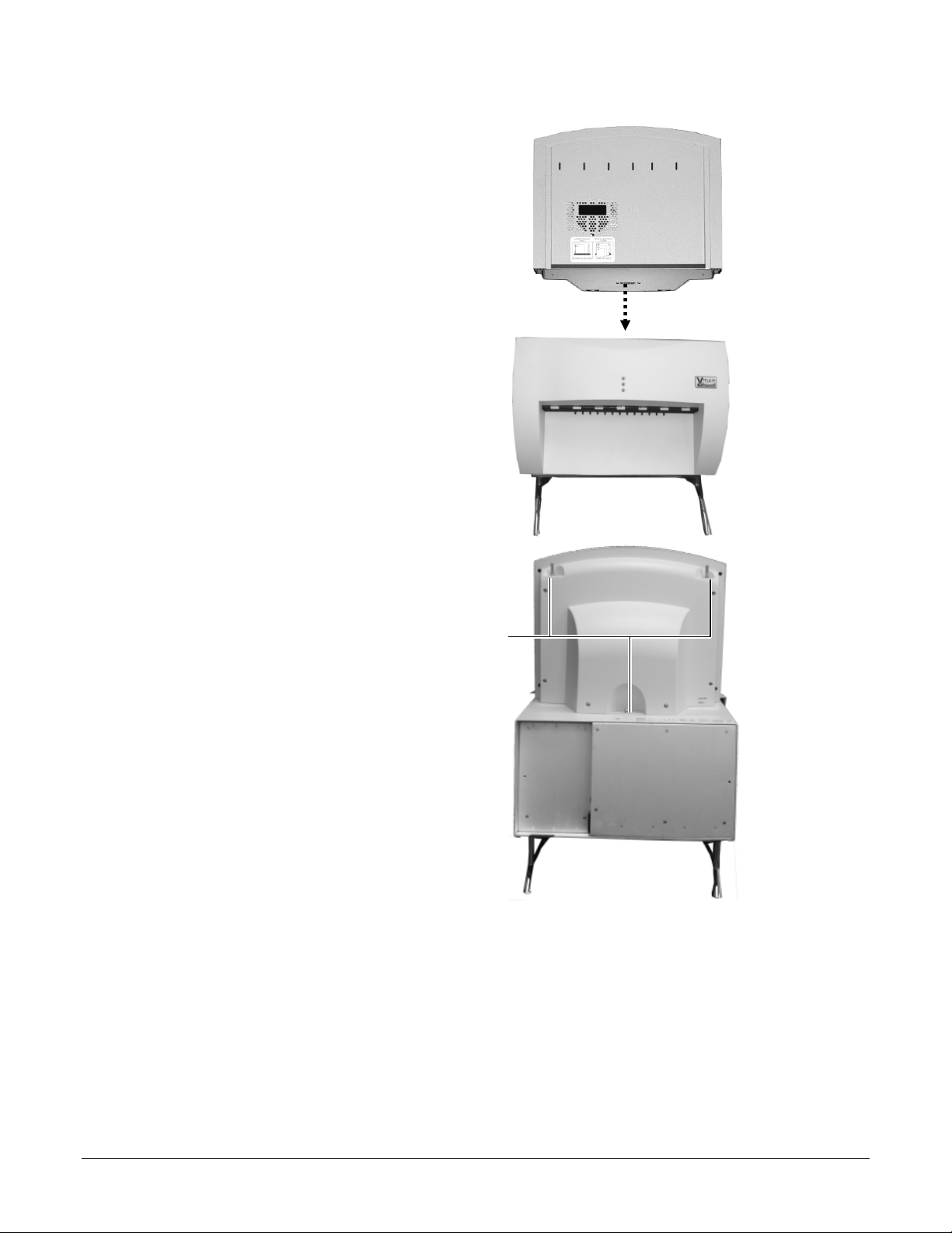
b. Place the feeder on top of the
digitizer, and slide the feeder
connector into the digitizer
connector.
c. On the rear of the feeder,
tighten the three screws to
secure the feeder to the
digitizer base.
You may need to move
the feeder slightly to get
the screws started in the
holes.
Tighten each screw a few
turns, then repeat until all
are finger tight.
Screws
19440-001 Rev. E VIDAR NDTPRO Industrial Film Digitizer Installation Guide 17
Page 18
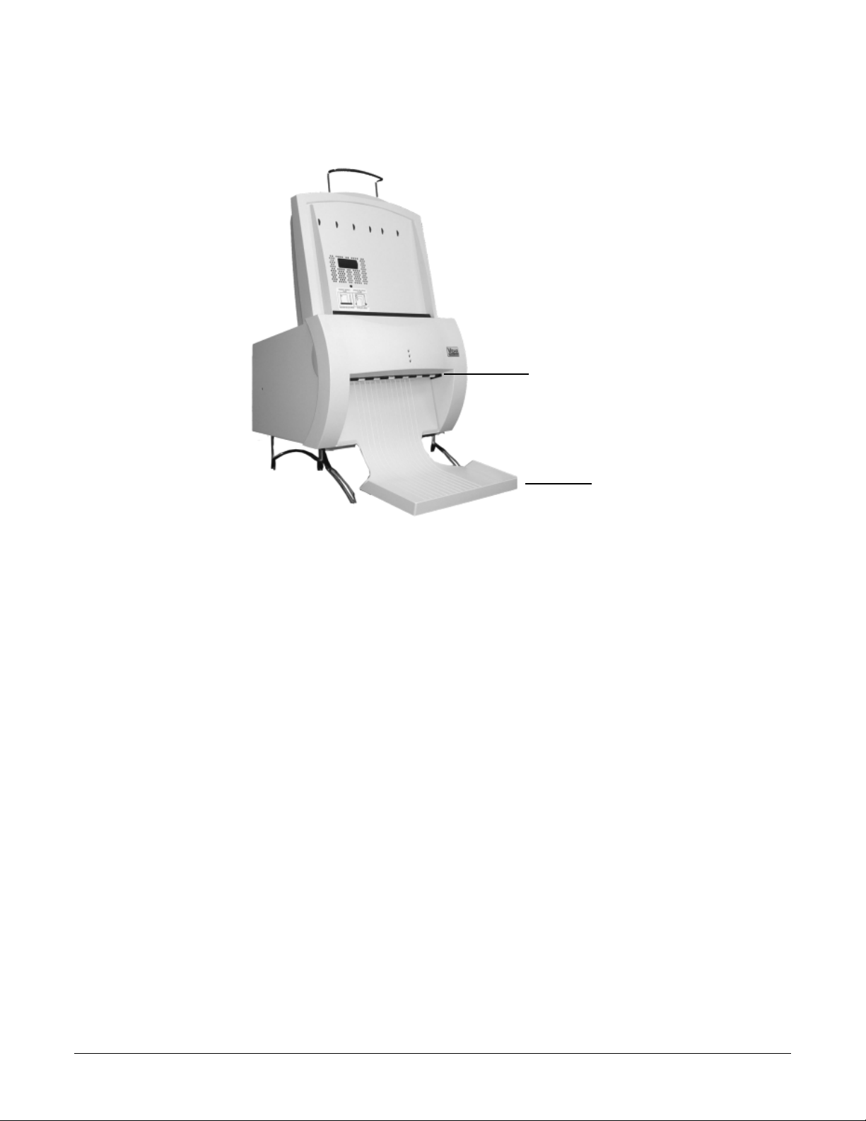
4. Install the exit tray by hooking it over the notched plastic edge just below the rollers.
When the exit tray is properly positioned, it will be parallel to the roller shaft.
Roller shaft
Exit tray
Properly installed exit tray
19440-001 Rev. E VIDAR NDTPRO Industrial Film Digitizer Installation Guide 18
Page 19
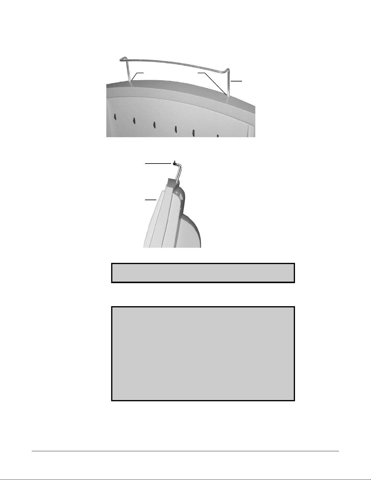
5. Insert the film support bar legs into the two holes on the film feeder’s top edge. The
film support bar’s curved center portion must face the front of the film feeder.
Holes in film feeder
Film support bar
Front of film feeder
Curved portion
of film support
Front of film
feeder
IMPORTANT: Do not lift or carry the digitizer using the film
support bar.
Warning
Before you begin the installation procedure, turn off all power to
the computer and peripherals.
Précaution
Avant de commencer la connexion, assurez vous que votre
ordinateur soit bien éteint.
Advertencia
Antes de continuar con la instalación, favor de apagar su
computadora y periférico.
Warnung
Vor dem Installieren den Computer und angeschlossene Geräte
ausschalten.
19440-001 Rev. E VIDAR NDTPRO Industrial Film Digitizer Installation Guide 19
Page 20
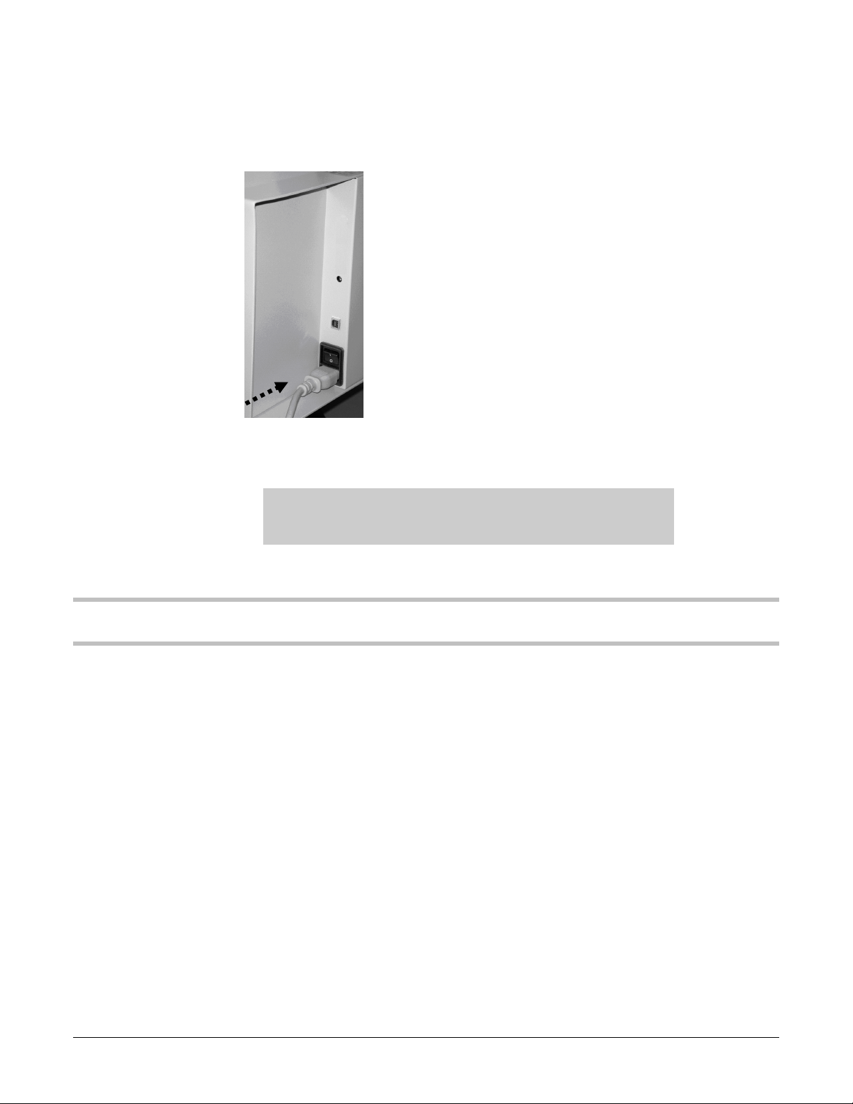
3. Connect the Power Cord
1. Connect the power cord to the digitizer’s Power Entry Module (PEM), located on the
rear of the digitizer.
2. Connect the other end of the power cord to a grounded power outlet.
Note: The film digitizer has an auto-sensing power supply.
When you apply power, the digitizer will detect the voltage and
set itself for proper operation.
NEXT: “Device Driver Installation”
19440-001 Rev. E VIDAR NDTPRO Industrial Film Digitizer Installation Guide 20
Page 21
Device Driver Installation
Install Device Drivers for Windows 7, 8, and 10
The USB driver is required for all installations to assure that the computer communicates with the digitizer.
1. Apply Power to the Digitizer
a. Ensure the PC is turned off.
Note: Always turn on the digitizer before turning on the
computer. This enables the computer to recognize the digitizer.
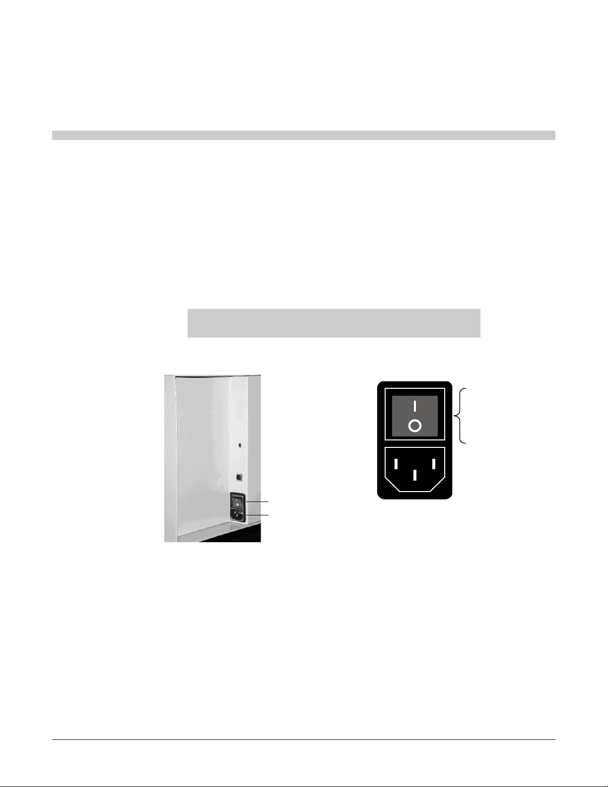
b. Turn on the digitizer. The on/off switch is located on the back of the digitizer.
c. Wait for all three LEDs on the front of the digitizer to turn green.
Digitizer base, rear view
ON/OFF Switch
Power Entry module
Power switch and power entry module
ON/OFF switch
(a rocker switch)
Press I to turn power ON.
Press 0 to turn power OFF.
19440-001 Rev. E VIDAR NDTPRO Industrial Film Digitizer Installation Guide 21
Page 22

2. About the VIDAR Drivers
The VIDAR driver is designed to provide compatibility between VIDAR NDTPRO
Digitizers and Windows 7, 8, & 10. Features of this driver include:
Installation/setup wizard for easy and consistent installation.
3. Install the VIDAR Drivers
Note: The computer must be running Windows 7, 8, & 10
Professional 32-bit or 64-bit.
Note: These instructions have been successfully tested on a
wide range of Windows 7, 8, & 10 systems. In rare instances,
you may have difficulty installing the VIDAR driver. If that
happens, try again after logging on as Administrator, or as a
user with Administrator rights.
You will need the VIDAR NDTPRO Industrial Film Digitizer CD.
a. Be sure the digitizer is turned ON and all three LEDs are green, but that it is NOT
connected to the PC. Wait until you are prompted to connect the digitizer to the PC.
b. Turn on the PC.
c. Insert the VIDAR NDTPRO Industrial Film Digitizer CD into the CD-ROM drive.
Browse to the CD and double-click on 19090-003 VIDAR_Driver_6.1 Online Install
Package.exe on the CD to install the driver.
19440-001 Rev. E VIDAR NDTPRO Industrial Film Digitizer Installation Guide 22
Page 23
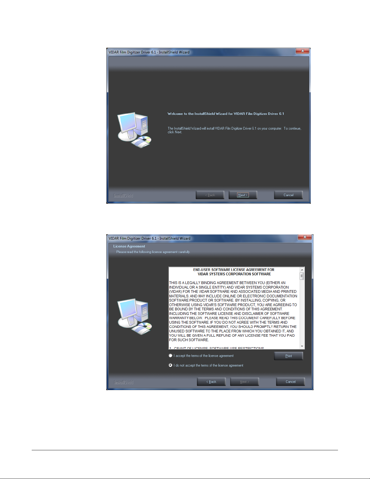
d. In the first screen, click Next >.
e. In the License Agreement screen, activate I accept the terms of the license
agreement, then click Next >.
19440-001 Rev. E VIDAR NDTPRO Industrial Film Digitizer Installation Guide 23
Page 24
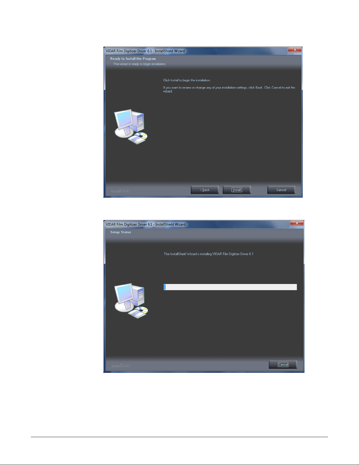
f. In the Ready to Install the Program screen, click Install.
g. The Setup Status screen will appear. Wait while the files are installed.
19440-001 Rev. E VIDAR NDTPRO Industrial Film Digitizer Installation Guide 24
Page 25
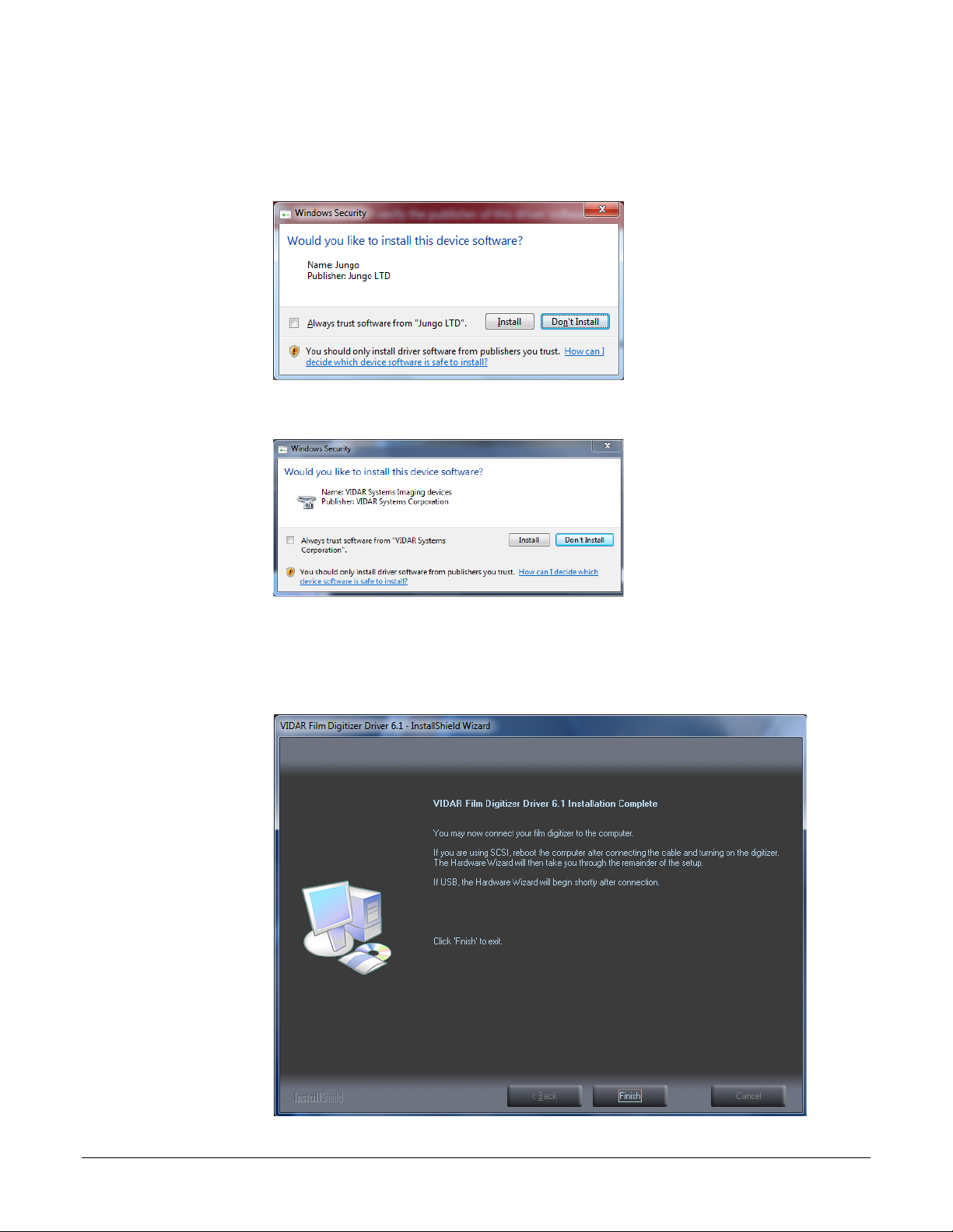
h. When prompted “Would you like to install this device software?” Click Install.
When installing on Windows 7, 8, & 10, 64 bit the name will appear as Jungo
i. When installing on Windows 7, 8, & 10, 32 bit the name will appear as VIDAR
j. InstallShield will indicate that installation is complete. However, the driver
installation is not complete.
19440-001 Rev. E VIDAR NDTPRO Industrial Film Digitizer Installation Guide 25
Page 26
k. Earlier, you connected a USB cable to the digitizer. Now, attach the connector on the
other end of that cable to a USB 2.0 or 3.0 port on the computer.
Note: Wait 30 seconds after you connect the digitizer before
you launch the VIDARInfo program. This ensures the computer
has recognized the new hardware and has installed the driver
properly.
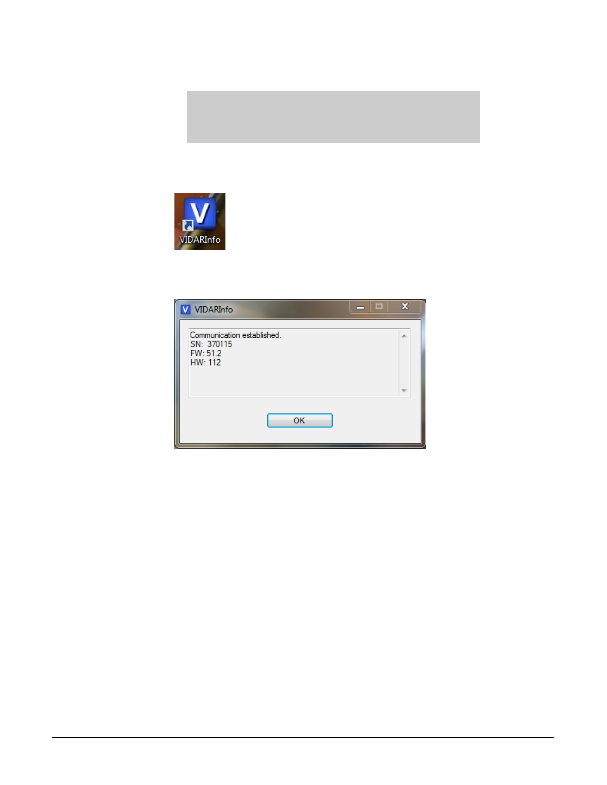
l. When using Windows 7, 8, & 10 64 bit - On the desktop, double-click the
VIDARINFO icon.
m. The window shown below will appear. This indicates that the digitizer is
communicating with the computer.
n. Click “OK” if the Digitizer Information is present on the Screen.
19440-001 Rev. E VIDAR NDTPRO Industrial Film Digitizer Installation Guide 26
Page 27
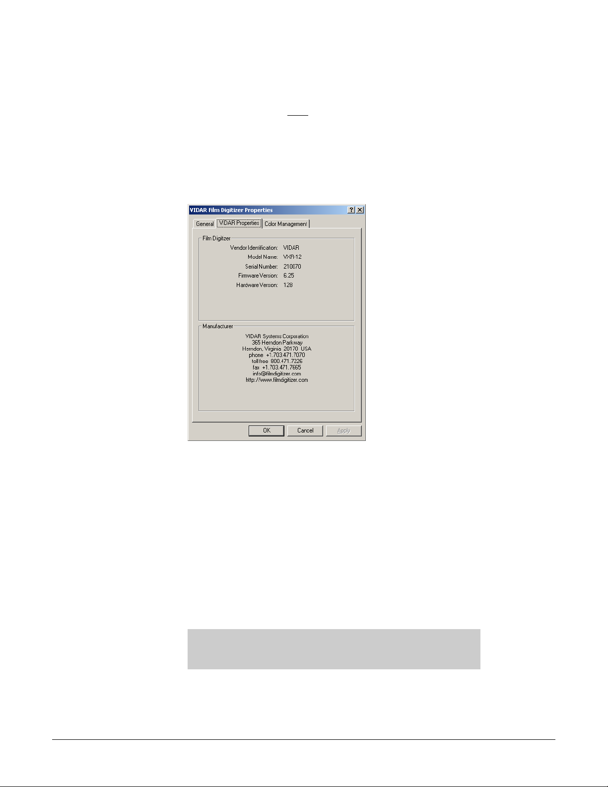
If using a 32 Bit OS
1.
Start > Control Panel > Scanners and Cameras.
2. In the device window, right-click VIDAR Film Digitizer, then click Properties in
the pop-up menu.
3. In the VIDAR Film Digitizer Properties window, click the VIDAR Properties
tab. If the driver is properly installed, the properties will appear and if the digitizer
is ready to digitize its serial number will appear. If Not Ready appears the
digitizer is normalizing.
Note that:
The digitizer will report as “VXR-12” for backward compatibility.
You may not see the same firmware and hardware version as shown in the
window above.
The serial number will not report if the digitizer was just powered on.
The digitizer is now ready to operate. Please refer to the “User’s Guide for VIDAR
NDTPRO Digitizers” found on the VIDAR NDTPRO Industrial Film Digitizer CD for
operating instructions.
You may need to install other scanning application software to run the digitizer.
Note: While the digitizer works with both 32-bit and 64-bit
versions of Windows 7, 8, & 10, it only works with 32-bit image
processing applications.
o. Additional communication testing can be found on the next page if VIDARInfo does
not properly populate as expected above.
19440-001 Rev. E VIDAR NDTPRO Industrial Film Digitizer Installation Guide 27
Page 28
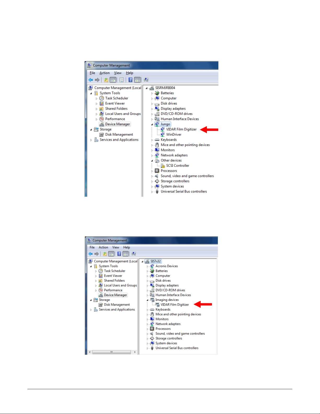
In the Computer Management window, the digitizer is listed under different name
depending on the Bit of the OS.
When using Window 7, 8, & 10 64 Bit OS the Digitizer is listed under Jungo
When using Window 7, 8, & 10 32 Bit OS the Digitizer will be listed under Imaging
Devices
19440-001 Rev. E VIDAR NDTPRO Industrial Film Digitizer Installation Guide 28
Page 29

Appendix:
Electromagnetic Guidance
Caution: Medical electrical equipment.
EMC (Electro Magnetic Compatibility) must be considered before any medical electrical equipment is installed or
put into service. Follow the information in the accompanying documentation when installing and operating the
VIDAR Digitizer.
Caution: Portable or mobile RF communication equipment can effect Medical Electrical equipment.
Caution: Using the Digitizer adjacent to or stacked with other equipment may cause interference between the
equipment. Before utilizing stacked or adjacent equipment, verify proper functionality of all equipment in the
actual configuration in which it will operate.
Caution: Connecting the Digitizer to equipment that is not rated CISPR 11 class A or class B may alter the
electromagnetic characteristics.
Caution: In a domestic environment this product may cause radio interference in which case the user may be
required to take adequate measures.
Guidance and manufacturer’s declaration –
electromagnetic equipment
Emissions test Compliance Electromagnetic environment - guidance
The Digitizers use RF energy only for their internal functions.
Group 1
RF Emissions
CISPR11
Class A
Therefore, its RF emissions are very low and are not likely to cause
any interference in nearby electronic equipment.
The Digitizers are suitable for use in all establishments other than
domestic and those directly connected to the public low voltage
power supply network that supplies buildings used for domestic
purposes.
19440-001 Rev. E VIDAR NDTPRO Industrial Film Digitizer Installation Guide 29
Page 30
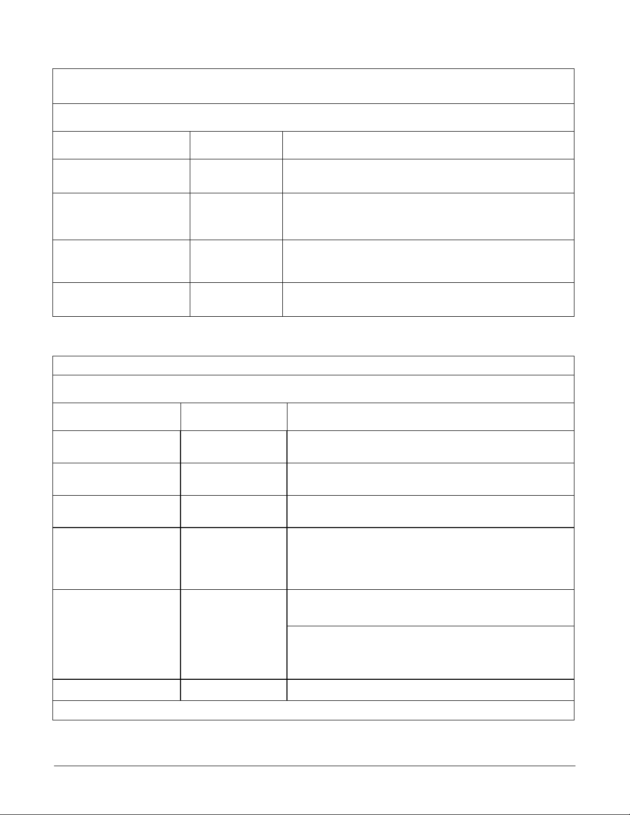
Guidance And Manufacturer’s Declaration – Electromagnetic Immunity
Enclosure Port
The VIDAR NDTPRO Industrial Film Digitizer is intended for use in the electromagnetic environment specified below. The
customer or end user of the Digitizer should assure that it is used in such an environment.
Immunity test Test method
Professional healthcare facility environment
Immunity Test Levels
Electrostatic Discharge (ESD) IEC 61000-4-2
± 8 kV contact
± 2 kV, ±4 kV, ± 8 kV, ± 15 kV air
3 V/m
Radiated RF EM fields IEC 61000-4-3
80 MHz – 2,7 GHz
80% AM at 1 kHz
Proximity fields from RF
wireless communications
IEC 61000-4-3 See Table A
equipment
Rated power frequency
magnetic fields
IEC 61000-4-8
30 A/m
50 or 60 Hz
Guidance And Manufacturer’s Declaration – Electromagnetic Immunity - Input a.c. power
The VIDAR NDTPRO Industrial Film Digitizer is intended for use in the electromagnetic environment specified below. The
customer or end user of the Digitizer should assure that it is used in such an environment.
Immunity test Test method
Electrical fast transient /
a) l) o)
bursts
Surges
a) b) j) o)
Line-to-line
Surges
a) b) j) k) o)
Line-to-ground
Conducted disturbances
induced by RF fields
Voltage dips
f) p) r)
Voltage interruptions
c) d) o)
f) i) o) r)
Professional healthcare facility environment
IEC 61000-4-4
± 2 kV
100 kHz repetition frequency
IEC 61000-4-5 ± 0,5 kV, ± 1 kV
IEC 61000-4-5 ± 0,5 kV, ± 1 kV, ±2 kV
m)
3 V
IEC 61000-4-6
0,15 MHz – 80 MHz
m)
6 V
in ISM bands between 0,15 MHz and 80 MHz
80 % AM at 1 kHz
0 % UT ; 0,5 cycle
At 0°, 45°, 90°, 135°, 180°, 225°, 270°, and 315°
IEC 61000-4-11
0 % UT ; 1 cycle
and
70 % UT ; 25/30 cycles
Single phase: at 0°
IEC 61000-4-11
0 % UT ; 250/300 cycle
Immunity Test Levels
e)
g)
h)
h)
q)
n)
Note: U
is the A.C. mains voltage prior to application of the test level.
T
19440-001 Rev. E VIDAR NDTPRO Industrial Film Digitizer Installation Guide 30
Page 31

Guidance And Manufacturer’s Declaration – Electromagnetic Immunity - Input a.c. power
Continued:
a) The test may be performed at any one power input voltage within the ME Equipment or ME SYSTEM RATED voltage
range. If the ME EQUIPMENT or ME SYSTEM is tested at one power input voltage, it is not necessary to re-test at
additional voltages.
b) All the ME EQUIPMENT and ME SYSTEM cables are attached during the test.
c) Calibration for current injection clamps shall be performed in a 150 Ω system.
d) If the frequency stepping skips over an ISM or amateur band, as applicable, an additional test frequency shall be
used in the ISM or amateur radio band. This applies to each ISM and amateur radio band within the specified
frequency range.
e) Testing may be performed at other modulation frequencies identified by the RISK MANAGEMENT PROCESS.
f) ME EQUIPMENT and ME SYSTEMS with a d.c. power input intended for use with a.c.- to – d.c. converters shall be
tested using a converter that meets the specifications of the MANUFACTURER of the ME EQUIPMENT or ME
SYSTEM. THE IMMUNITY TEST LEVELS are applied to the a.c. power input of the converter.
g) Applicable only to ME EQUIPMENT and ME SYSTEMS connected to single-phase a.c. mains.
h) E.g. 10/12 means 10 periods at 50 Hz or 12 periods at 60 Hz.
i) ME EQUIPMENT and ME SYSTEMS with RATED input current greater than 16 A / phase shall be interrupted one for
250/300 cycles at any angle and at all phases at the same time (if applicable). ME EQUIPMENT and ME SYSTEMS
with battery backup shall resume line power operation after the test. For ME EQUIPMENT and ME SYSTEMS with
RATED input current not exceeding 16 A, all phases shall be interrupted simultaneously.
j) ME EQUIPMENT and ME SYSTEMS that do not have a surge protection device in the primary power circuit may be
tested only at ± 2kV line(s) to earth and ± 1 kV line(s) to line(s).
k) Not applicable to CLASS II ME EQUIPMENT and ME SYSTEMS.
l) Direct coupling shall be used.
m) r.m.s., before modulation is applied.
n) The ISM (industrial, scientific and medical) bands between 0,15 MHz and 80 MHz are 6,765 MHz to 6,795
MHz; 13,553 MHz to 13,567 MHz; 26,957 MHz to 27,283 MHz; and 40,66 MHz to 40,70 MHz. The amateur
radio bands between 0,15 MHz and 80 MHz are 1,8 to 2,0 MHz, 3,5 MHz to 4,0 MHz, 5,3 MHz to 5,4 MHz, 7
MHz to 7,3 MHz, 10,1 MHz to 10,15 MHz, 14 MHz to 14,2 MHz, 18,07 MHz to 18,17 MHz, 21,0 MHz to 21,4
MHz, 24,89 MHz to 24,99 MHz, 28,0 MHz to 29,7 MHz and 50,0 MHz to 54,0 MHz.
o) Applicable to ME EQUIPMENT and ME SYSTEMS with RATED input current less than or equal to 16 A / phase and
ME EQUIPMENT and ME SYSTEMS with RATED input current greater than 16 A / phase.
p) Applicable to ME EQUIPMENT and ME SYSTEMS with RATED input current less than or equal to 16 A / phase.
q) At some phase angles, applying this test to ME EQUIPMENT with transformer mains power input might cause an
overcurrent protection device to open. This can occur due to magnetic flux saturation of the transformer core after the
voltage dip. If this occurs, the ME EQUIPMENT or ME SYSTEM shall provide BASIC SAFETY during and after the
test.
r) For ME EQUIPMENT and ME SYSTEMS that have multiple voltage settings or auto ranging voltage capability, the test
shall be performed at the minimum and maximum RATED input voltage. ME EQUIPMENT and ME SYSTEMS with a
RATED input voltage range of less than 25 % of the highest RATED input voltage shall be tested at one RATED input
voltage within the range.
Immunity to proximity fields form RF wireless communications equipment
The ENCLOSURE PORT of ME EQUIPMENT and ME SYSTEMS shall be tested as specified in Table A using the test
methods specified in IEC 61000-4-3.
The frequencies and services listed in Table A are representative examples that are based on RF communications equipment
in use at the time of publication of this collateral standard. The test specification does not attempt to cover every frequency
and service used in every country. The RISK MANAGEMENT PROCESS should take current communications services into
account. Testing should be performed at the additional frequencies identified that are not represented in Table A.
While communication might not be possible when ME EQUIPMENT that includes radio equipment is tested in its bandwidth,
the ME EQUIPMENT or ME SYSTEM shall still be able to provide its BASIC SAFETY and ESSENTIAL PERFORMANCE.
19440-001 Rev. E VIDAR NDTPRO Industrial Film Digitizer Installation Guide 31
Page 32
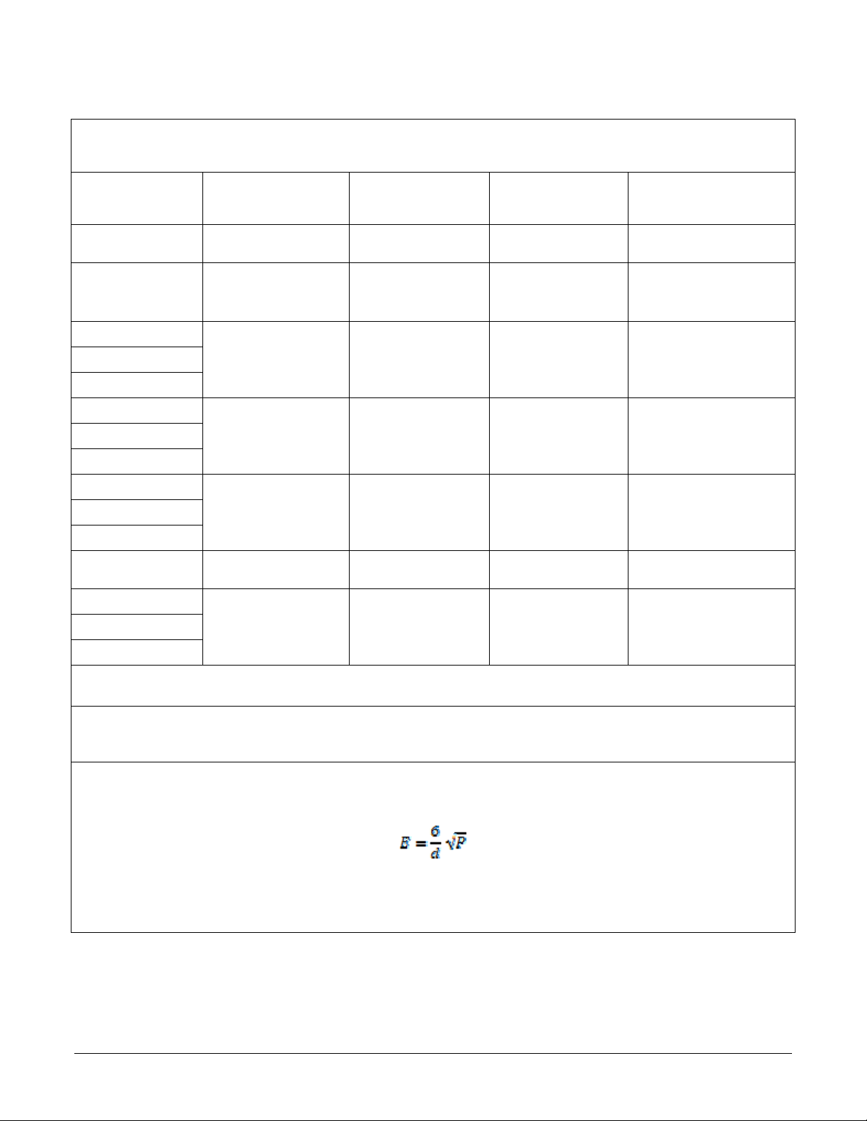
Table A- Test specifications for Enclosure Port immunity to RF wireless communications equipment.
The customer or the user of the VIDAR NDTPRO Industrial Film Digitizer can help prevent electromagnetic interference by
maintaining a minimum distance between portable and mobile RF communications equipment (transmitters) and the Digitizer
as recommended below, according to the maximum output power of the communications equipment.
Test frequency
(MHz)
385
450
710
745
780
810
870
930
a)
Modulation
Pulse modulation
18 Hz
b)
FM
±5 kHz deviation
1 kHz sine
Pulse modulation
217 Hz
Pulse modulation
18 Hz
Maximum power
(W)
Distance
(m)
1,8 0,3 27
2 0,3 28
0,2 0,3 9
2 0,3 28
Immunity
Test Level
(V/m)
1 720
1 845
Pulse modulation
217 Hz
2 0,3 28
1 970
2 450
Pulse modulation
217 Hz
2 0,3 28
5 240
5 500
Pulse modulation
217 Hz
0,2 0,3 9
5 785
NOTE: If necessary to achieve the Immunity Test Level, the distance between the transmitting antenna and the ME Equipment or ME System
may be reduced to 1 m. The 1 m test distance is permitted by IEC 61000-4-3
a) The carrier shall be modulated using a 50% duty cycle square wave signal.
b) As an alternate to FM modulation, 50% pulse modulation at 18 Hz may be used because while it does not represent actual modulation, it
would be worst case.
The Manufacturer should consider reducing the minimum separation distance, based on RISK MANAGEMENT, and using higher IMMUNITY
TEST LEVELS that are appropriate for the reduced minimum separation distance. Minimum separation distances for higher IMMUNITY TEST
LEVELS shall be calculated using the following equation:
Where P is the maximum power in W, d is the minimum separation distance in m, and E is the IMMUNITY TEST LEVEL in V/m.
If the ME EQUIPMENT or ME SYSTEM complies with the higher IMMUNITY TEST LEVELS for this test, the 30 cm minimum separation
distance (per above table) may be replaced with minimum separation distances calculated from the higher IMMUNITY TEST LEVELS.
19440-001 Rev. E VIDAR NDTPRO Industrial Film Digitizer Installation Guide 32
Page 33
Appendix:
Symbols
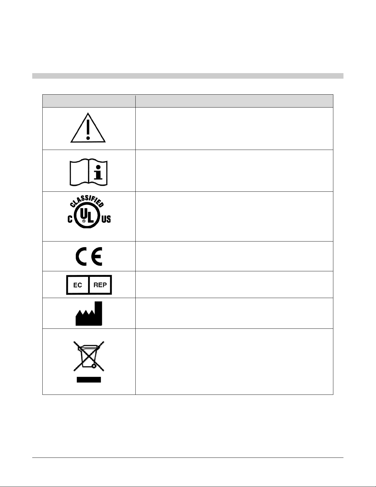
Symbol Description
Indicates the need for the user to consult the instructions for use for
important cautionary information such as warnings and precautions that
cannot, for a variety of reasons, be presented on the device itself.
Indicates the need for the user to consult the instructions for use.
5RA9
Underwriters Laboratories classification symbol
Compliance to EU Directives
Authorized Representative in the European Community
Indicates the Device Manufacturer
This symbol on the product indicates that this product must not be
disposed of as unsorted municipal waste. Instead it is your
responsibility to dispose of your waste equipment by handing it over to
a designated collection point for recycling of waste electrical and
electronic equipment. For more information about where you can
dispose of your waste equipment for recycling please contact your local
city office, your household waste disposal service or the shop where
you purchased the product.
19440-001 Rev. E VIDAR NDTPRO Industrial Film Digitizer Installation Guide 33
Page 34

365 Herndon Parkway
Phone:
Fax:
Web:
Technical Support:
Phone:
Email:
Herndon, VA 20170
+1.703.471.7070
+1.703.471.7665
www.vidar.com
+1.703.471.7070
+1.800.471.7226
+1.703.471.7665
[email protected]
 Loading...