

Vicway VT 1000E, VT PRO Installation Instructions And User Manual
www.vicway.com.au
Garage Door Driver
Installation Instructions and User Guide
VT 1000E
VT PRO
WARNING
Please read the manual carefully before installation and use. The
installation of your new door opener must be carried out by a technically
qualified or licensed person. Attempting to install or repair the door opener
without suitable technical qualification may result in severe personal injury,
death and / or property damage.

CONTENTS
Important safety recommendations..…………………………….……………………………..1-2
Basic function introduction……… ..……………………………………………….……………... 3
Special function introduction………….…………………………………………………………..3
Installation……….………………………………………………………………………………….4
Installation (steel track)………………………………………….…………………………….…..4-11
Installation (sectional steel track)…………………………………………………………………11
Installation recommendations……………………………………………………………………..12
Basic function setting and applying…………………………………………………………....13-14
Special function introduction and application………………………………………….……….15
Manual disengagement…………………………………………………………………………. 16
Maintenance………………………………………………………………………………………..17
Technical specifications…………………………………………………………………………. .17
Manufacturer ’s declaration………………………………………………………………………..18
Final note….………………………………………………………………………………………...18
Important information for the user………………………………………………………………...18
Packing list….……………………………………………………………………………………….19
Warranty….………………………………………………………………………………………20-22

- 1 -
Important safety recommendations
The new GDO is professionally designed under the newest design idea of Vicway Australia Pty
Ltd. The installation and setting of this GDO is extremely easy. It has complete functions, gives
the users a relaxed and happy installation experience.
Safety Warnings
Warning: It is very important to read this safety warnings and follow all instructions before
installing. Or it may cause serious personal injury and/or property loss. Save these
instructions.
1. This appliance can be used by children aged from 8 years and above and persons with
reduced physical, sensory or mental capabilities or lack of experience and knowledge if they
have been given supervision or instruction concerning use of the appliance in a safe way and
understand the hazards involved. Children shall not play with the appliance or its controls,
including transmitters. Keep the transmitters out of the reach of children. Cleaning and user
maintenance shall not be made by children without supervision.
2. We strongly recommend to install photocell to increase safety protection and psychological
security.
3. Before installing the drive, remove all unnecessary ropes or chains and disable any
equipment, such as locks, not needed for powered operation. Check that the door is in good
mechanical condition, correctly balanced and opens and closes properly.
4. A-weighted emission sound pressure level of the drive LpA ≤ 70 dB(A).
5. The operator must not be used for doors without a safety catch.
6. Install the actuating member for the manual release at a height less than 1.8 m. If removable,
the actuating member should be stored in direct vicinity of the door.
7. Install any fixed control at a height of at least 1.5 m and within sight of the door but away
from moving parts.
8. Wall switch or wall transmitter must be installed out of the reach of children.
9. Permanently fix the labels warning against entrapment in a prominent place or near any
fixed controls.
10. Permanently fix the label concerning the manual release adjacent to its actuating member.
11. After installation, ensure that the mechanism is properly adjusted and that the drive
reverses or the object can be freed when the door contacts a 40 mm high object placed on the
floor. Ensure that parts of the door do not extend over public footpaths or roads.
12. Refer to pages 4-8 for information on how to adjust the door and drive.
13. Connect the GDO to 220-240V circuit, and fix it to the required place by professional
person.
WARNING: The drive shall be disconnected from its power source during cleaning,
maintenance and when replacing parts.

- 2 -
14. Waste electrical products should not be disposed of with household waste.
Please recycle where facilities exist. Check with your local authority or retailer for
recycling advice.
15. If the supply cord is damaged, it must be replaced by the manufacturer, its service agent or
similarly qualified persons in order to avoid a hazard.
16. Watch the moving door and keep people away until the door is completely opened or
closed.
17. Take care when operating the manual release since an open door may fall rapidly due to
weak or broken springs, or being out of balance. (Refer to page 12 of the instructions for
information concerning use of the manual release.)
18. Check the condition of the door frequently if has any damage or if is well balanced.,
especially the cable, spring, components connect with the wall. Don’t use the door if it is not
repaired or adjusted, or there will be injury due to improper installation or bad balance. If the
door components are under extreme pressure, don’t repair it by yourself, if necessary, call for
authorized service.
19. Each month check that the drive reverses or the object can be freed when the door
contacts a 40mm high object placed on the floor.
20. The drive must not be used with a door incorporating a wicket door (unless the drive can
not be operated with the wicket door not put in the safe position).
If applicable, that the drive is not to be used with doors having openings exceeding 50 mm in
diameter or having edges or protruding parts a person could grip or stand on.
21. Don’t open/close the door when people are near the door. Keep children away from the
moving door. Or it may cause serious personal injury and/or property loss.
22. In order to keep the GDO away from the rain, don’t expose it out door. Don’t put the GDO
in the water, don’t spray water to the GDO, keep the GDO away from any other device with
water.
23. In order to make sure the GDO can sense the obstacle under the door, the door must press
the obstacle. So it may cause injury or damage to the obstacle, door or person.
24. If the circuit is damaged, the professional person is required to do the repair.
25. Make sure the garage door is fully open & stationary before passing through the door.
Make sure the garage door is fully closed & stationary before leaving.
WARNING: Automatic door – The door may operate unexpectedly, therefore do not
allow anything to stay in the path of the door.

- 3 -
Basic function introduction
1. Soft start, soft stop. Keep the garage door steadily and reliably operation
2. The door will stop during opening when contacting obstruction, and will reverse at least
30cm during closing when contacting obstruction.
3. Opening & closing force dynamically self-learning. Can make sure the garage door driver
will work steadily in spite of change of door resistance by seasonal variation.
4. The door safety closing resistance force is adjustable with 9 rates.
5. Wall switch terminal available.
6. Infra-red security protection
7. Low-voltage protection, the process will not perform any action of opening and closing
when voltage is too low, door panel and controller won’t be damaged.
8. We adopt rolling code transmitter, with billions of codes, won’t be coincident code or
pirated code.
9. Optional battery back-up terminal, when power failure, the door driver can still keep on
working, help to open/close the door as normal (see the connect terminal on the control
board).
10. With auto-closing feature. The auto-close time is adjustable in 10 rates.
Special function introduction (optional)
The following functions are made to order in accordance with the special needs of
customers:
1. Caution light feature
2. Passing door feature
3. OPEN CODE function
- 4 -
Installation
1). Read the instructions carefully.
2). Make sure the door structure is solid and suitable to
be motor driven.
3). Make sure that when the door is moving there are no
friction points.
4). The door must be properly balanced and must be
easily lowered and raised by hand.
5). Install a 220V, adequately protected 3-pin socket near
Where the GDO is going to be installed.
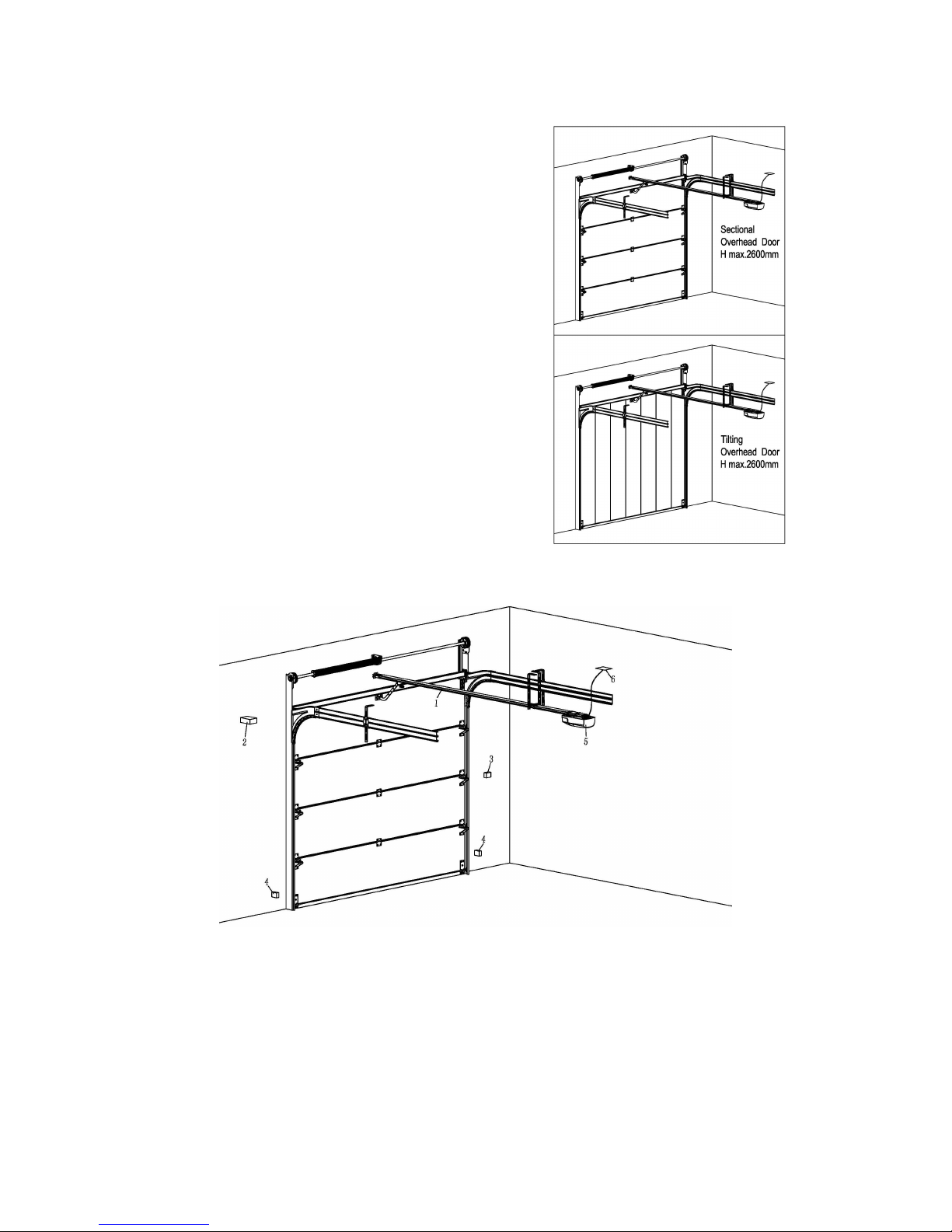
FIG.1
FIG.2
Referring to FIG. 2 for recommended installation
(1) Sectional door rail (2) 24V DC flashing light (optional extra)
(3) Wall button (4) Safety sensor
(5) Interaction panel (6) Power socket
- 5 -
Installation (steel track)
FIG. 3
FIG. 4
- 6 -
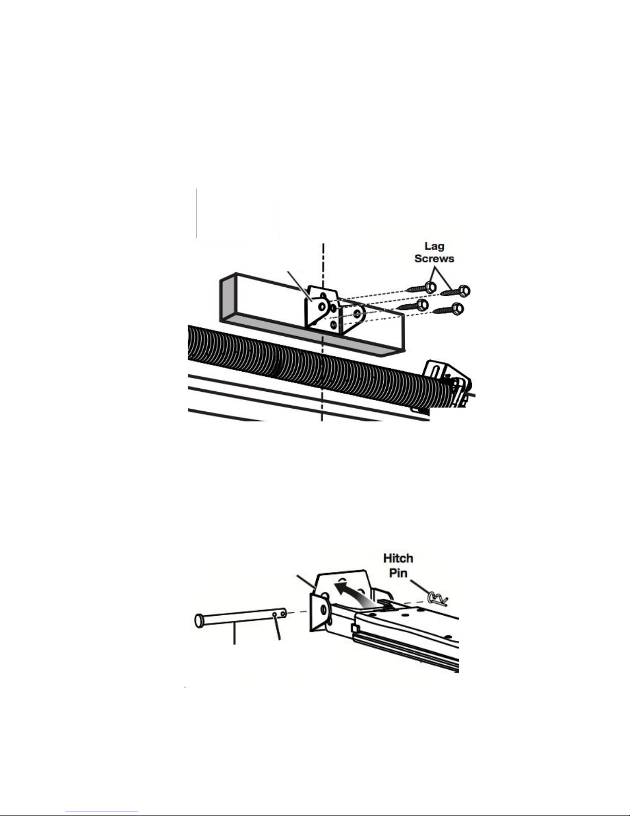
1. Install the track bracket. Locate the position (over the shaft or intermediate bracket for
2cm-15cm, depending on the actual installation space) of the track bracket. Drill four
pilot holes corresponding to the bracket. Mount the track bracket to the wall with
fourM8×40 lag screws by a 1/2-inch socket.
FIG. 5
2. Mount the steel track to the bracket. Align the holes in the bracket and the holes in the
track, then insert theφ8×90cotter pin. Secure by installing the 1.8×38 hitch pin into the
two holes of the cotter pin (FIG. 6)
FIG. 6
Track
Bracket
Cotter pin
First Hole
Track
Bracket
 Loading...