

www.vicway.com.au
Garage Door Driver
Installation Instructions and User Guide
VT 1000E
VT PRO
WARNING
Please read the manual carefully before installation and use. The
installation of your new door opener must be carried out by a technically
qualified or licensed person. Attempting to install or repair the door opener
without suitable technical qualification may result in severe personal injury,
death and / or property damage.

CONTENTS
Important safety recommendations..…………………………….……………………………..1-2
Basic function introduction……… ..……………………………………………….……………... 3
Special function introduction………….…………………………………………………………..3
Installation……….………………………………………………………………………………….4
Installation (steel track)………………………………………….…………………………….…..4-11
Installation (sectional steel track)…………………………………………………………………11
Installation recommendations……………………………………………………………………..12
Basic function setting and applying…………………………………………………………....13-14
Special function introduction and application………………………………………….……….15
Manual disengagement…………………………………………………………………………. 16
Maintenance………………………………………………………………………………………..17
Technical specifications…………………………………………………………………………. .17
Manufacturer ’s declaration………………………………………………………………………..18
Final note….………………………………………………………………………………………...18
Important information for the user………………………………………………………………...18
Packing list….……………………………………………………………………………………….19
Warranty….………………………………………………………………………………………20-22

- 1 -
Important safety recommendations
The new GDO is professionally designed under the newest design idea of Vicway Australia Pty
Ltd. The installation and setting of this GDO is extremely easy. It has complete functions, gives
the users a relaxed and happy installation experience.
Safety Warnings
Warning: It is very important to read this safety warnings and follow all instructions before
installing. Or it may cause serious personal injury and/or property loss. Save these
instructions.
1. This appliance can be used by children aged from 8 years and above and persons with
reduced physical, sensory or mental capabilities or lack of experience and knowledge if they
have been given supervision or instruction concerning use of the appliance in a safe way and
understand the hazards involved. Children shall not play with the appliance or its controls,
including transmitters. Keep the transmitters out of the reach of children. Cleaning and user
maintenance shall not be made by children without supervision.
2. We strongly recommend to install photocell to increase safety protection and psychological
security.
3. Before installing the drive, remove all unnecessary ropes or chains and disable any
equipment, such as locks, not needed for powered operation. Check that the door is in good
mechanical condition, correctly balanced and opens and closes properly.
4. A-weighted emission sound pressure level of the drive LpA ≤ 70 dB(A).
5. The operator must not be used for doors without a safety catch.
6. Install the actuating member for the manual release at a height less than 1.8 m. If removable,
the actuating member should be stored in direct vicinity of the door.
7. Install any fixed control at a height of at least 1.5 m and within sight of the door but away
from moving parts.
8. Wall switch or wall transmitter must be installed out of the reach of children.
9. Permanently fix the labels warning against entrapment in a prominent place or near any
fixed controls.
10. Permanently fix the label concerning the manual release adjacent to its actuating member.
11. After installation, ensure that the mechanism is properly adjusted and that the drive
reverses or the object can be freed when the door contacts a 40 mm high object placed on the
floor. Ensure that parts of the door do not extend over public footpaths or roads.
12. Refer to pages 4-8 for information on how to adjust the door and drive.
13. Connect the GDO to 220-240V circuit, and fix it to the required place by professional
person.
WARNING: The drive shall be disconnected from its power source during cleaning,
maintenance and when replacing parts.

- 2 -
14. Waste electrical products should not be disposed of with household waste.
Please recycle where facilities exist. Check with your local authority or retailer for
recycling advice.
15. If the supply cord is damaged, it must be replaced by the manufacturer, its service agent or
similarly qualified persons in order to avoid a hazard.
16. Watch the moving door and keep people away until the door is completely opened or
closed.
17. Take care when operating the manual release since an open door may fall rapidly due to
weak or broken springs, or being out of balance. (Refer to page 12 of the instructions for
information concerning use of the manual release.)
18. Check the condition of the door frequently if has any damage or if is well balanced.,
especially the cable, spring, components connect with the wall. Don’t use the door if it is not
repaired or adjusted, or there will be injury due to improper installation or bad balance. If the
door components are under extreme pressure, don’t repair it by yourself, if necessary, call for
authorized service.
19. Each month check that the drive reverses or the object can be freed when the door
contacts a 40mm high object placed on the floor.
20. The drive must not be used with a door incorporating a wicket door (unless the drive can
not be operated with the wicket door not put in the safe position).
If applicable, that the drive is not to be used with doors having openings exceeding 50 mm in
diameter or having edges or protruding parts a person could grip or stand on.
21. Don’t open/close the door when people are near the door. Keep children away from the
moving door. Or it may cause serious personal injury and/or property loss.
22. In order to keep the GDO away from the rain, don’t expose it out door. Don’t put the GDO
in the water, don’t spray water to the GDO, keep the GDO away from any other device with
water.
23. In order to make sure the GDO can sense the obstacle under the door, the door must press
the obstacle. So it may cause injury or damage to the obstacle, door or person.
24. If the circuit is damaged, the professional person is required to do the repair.
25. Make sure the garage door is fully open & stationary before passing through the door.
Make sure the garage door is fully closed & stationary before leaving.
WARNING: Automatic door – The door may operate unexpectedly, therefore do not
allow anything to stay in the path of the door.

- 3 -
Basic function introduction
1. Soft start, soft stop. Keep the garage door steadily and reliably operation
2. The door will stop during opening when contacting obstruction, and will reverse at least
30cm during closing when contacting obstruction.
3. Opening & closing force dynamically self-learning. Can make sure the garage door driver
will work steadily in spite of change of door resistance by seasonal variation.
4. The door safety closing resistance force is adjustable with 9 rates.
5. Wall switch terminal available.
6. Infra-red security protection
7. Low-voltage protection, the process will not perform any action of opening and closing
when voltage is too low, door panel and controller won’t be damaged.
8. We adopt rolling code transmitter, with billions of codes, won’t be coincident code or
pirated code.
9. Optional battery back-up terminal, when power failure, the door driver can still keep on
working, help to open/close the door as normal (see the connect terminal on the control
board).
10. With auto-closing feature. The auto-close time is adjustable in 10 rates.
Special function introduction (optional)
The following functions are made to order in accordance with the special needs of
customers:
1. Caution light feature
2. Passing door feature
3. OPEN CODE function
- 4 -
Installation
1). Read the instructions carefully.
2). Make sure the door structure is solid and suitable to
be motor driven.
3). Make sure that when the door is moving there are no
friction points.
4). The door must be properly balanced and must be
easily lowered and raised by hand.
5). Install a 220V, adequately protected 3-pin socket near
Where the GDO is going to be installed.
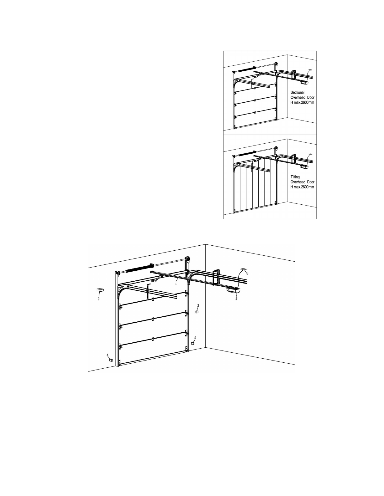
FIG.1
FIG.2
Referring to FIG. 2 for recommended installation
(1) Sectional door rail (2) 24V DC flashing light (optional extra)
(3) Wall button (4) Safety sensor
(5) Interaction panel (6) Power socket
- 5 -
Installation (steel track)
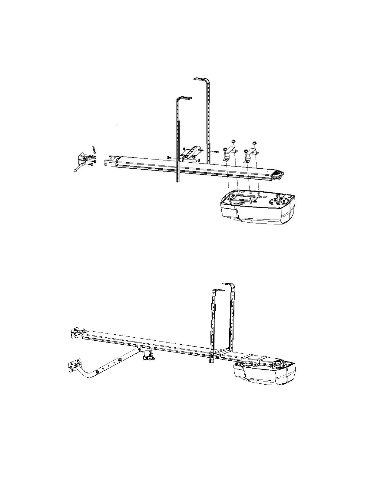
FIG. 3
FIG. 4
- 6 -
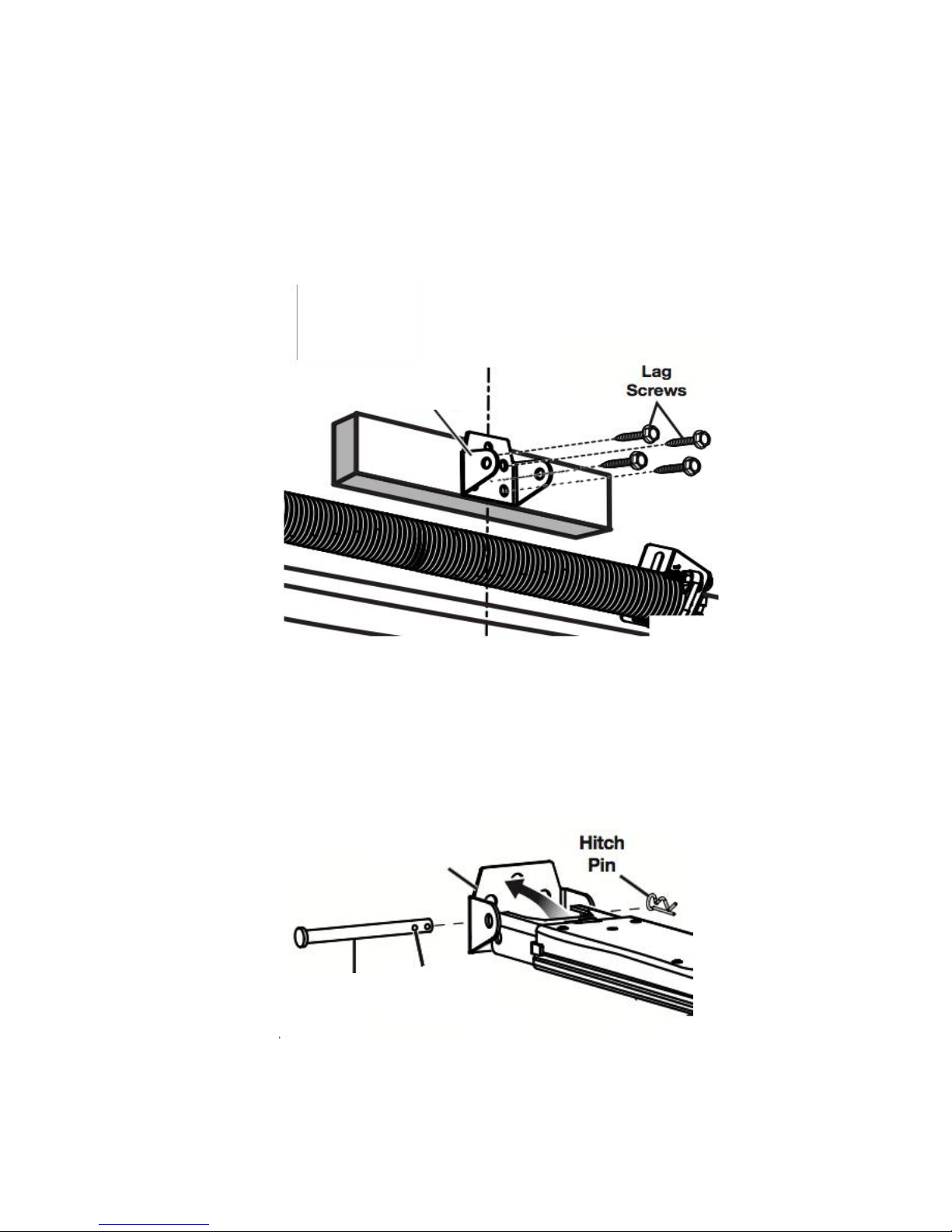
1. Install the track bracket. Locate the position (over the shaft or intermediate bracket for
2cm-15cm, depending on the actual installation space) of the track bracket. Drill four
pilot holes corresponding to the bracket. Mount the track bracket to the wall with
fourM8×40 lag screws by a 1/2-inch socket.
FIG. 5
2. Mount the steel track to the bracket. Align the holes in the bracket and the holes in the
track, then insert theφ8×90cotter pin. Secure by installing the 1.8×38 hitch pin into the
two holes of the cotter pin (FIG. 6)
FIG. 6
Track
Bracket
Cotter pin
First Hole
Track
Bracket

- 7 -
3. Install garage door opener. As shown below, align the motor shaft to the hole on the
track. Then, align the two U hanging brackets A to the four studs respectively. The
studs shall be through the holes on the U hang bracket A, and thus the whole
assembly can be mounted by fourM4 nuts. At this point, the whole assembly should be
rotatable vertically along the axle, which is the cotter pin.
FIG. 7
M4 Nut
U hanging
bracket A
Stud

- 8 -
4. Install the hanging bracket. Position the hanging bracket on the track as closer to the
opener as possible, if there is enough space. Note, some angle are needed to place
the hanging bracket on the track. By rotating the hanging bracket for about 30°(this
requires to apply certain force), it can be fixed on the track sturdy. Then determine
mounting points on both of the iron angle A, where the distance between the measure
the distance between the mounting points and ceiling enable the track to be horizontal
when hanging. Then mount the hanging bracket at mounting points by two pairs of M4
screws and M4 nuts. Still, the whole assembly should be rotatable vertically, where the
axle is the cotter pin.
Notice: Ensure the track is horizontal and vertical to the shaft. Ensure the connection
between iron angle A and ceiling is firm enough.
FIG. 8
Hanging
Bracket
Iron angle A
M4 Screw
M4 Nut

- 9 -
5. Lift the track horizontally, such that the top of the iron angle A may contact the ceiling
just right. Then, determine two mounting points for M8 screws. Drill two pilot holes at
the mounting points, insert the two 10×50 expansion pipes, and mount the hanging
bracket onto the ceiling by two M8 screws. Make sure the whole assembly is steady.
6. The connection of panel bracket and panel connector refers to the installation of
aluminum track.
7. Connect the door and the garage door opener.
• Install the door bracket at the top of the center line of the door by two M6 screws.
FIG. 9
• Connect the straight arm and the trolley by 1.8×38 hitch pin and φ8×25 cotter pin.
• Connect the bent arm and the door bracket by 1.8×38 hitch pin and φ8×25 cotter pin.
FIG. 10
Centre
Line

- 10 -
• Move the trolley to an appropriate position in order to connect the bent arm and the
straight arm by two pairs of M6 nuts and M6 bolts.
FIG. 11
FIG. 12
Clutch
Cord
M6
Bolt
M6
Nut
Cotter
pin
Trolley

- 11 -
8. Connect the clutch cord to the trolley.
9. Release the clutch by pulling down the clutch cord. Try to open and close the door by
hand. Make sure there is no abnormal resistance between door panel and track along
the whole travel.
10. Connect the opener with power supply and set up the opener.
Notice: Make sure the opener’s voltage is in accordance with the local voltage. Connect
the opener to a properly earthed power supply.
Installation (sectional steel track)
•
Put the trolley into the track
FIG. 13

- 12 -
Installation recommendations
Remem ber there are specific standards that have to be strictly followed regarding the safety
rules of electrical installations and automatic gates and doors.
As for the legal requirements and standards that must be adhered to, please take notice of the
following points to ensure maximum safety and reliability of your installation.
1. Before installing check the surrounding environment. Carefully evaluate any hazards which
could be physical damage (transiting vehicles, parts of trees falling etc.), possible contact with
persons’ bodies (insects, leaves, etc.), flooding hazards, or any others exceptional events.
2. Check the main voltage numbers is the same as the numbers that are given on the rating
plate and in this manual.
3. Check and make sure if there is suitable electrical protection against short circuits/power
spikes and proper earthing on the main supply.
Remem ber the unit having main voltage running through it (electrocution hazard, fire hazard).
4. Take care with the control unit; the parts may be subject to damage if the control unit is
abused.
5. Make sure that you have all the necessary materials, and they are suitable for this kind of
use.
6. Read all the instructions thoroughly, and make sure they are understood before attempting
to install the opener.
7. Before starting the installation carefully analyze all the risks relating to automating the door.
Verify that the door is automated in a sound condition and that the mechanisms are in good
working order. Observe the safety margins and minimum distances.
8. Carefully evaluate the safety devices to be installed and the right place to install them;
always install an emergency stop device for power interruption to the opener if it is required.
9. Once the risks have been analyzed, install the opener and relative safety devices,
emergency stop and/or photoelectric cells.
Impor tant note: As for additional safety rules, we strongly recommends the fitting of Photo
Electric safety beams on all installations.
10. While installing the opener, strictly follow all the instructions given in the instruction manual.
If some points or procedures in this manual are not very clear do not install the unit until all
doubts have been cleared up with our technical department.

- 13 -
Basic function setting and applying
1. Itinerary setting
Opening & closing force dynamically self-learning
2. Matching the receiver and transmitter
Fig. A
Fig. B
3. Safety reverse force adjustment
Press ‘SET’ button and hold on until the LED displays
figure ‘1’, then adjust the up limit by pressing ‘up’ button.
Fine-tuning ‘up’ or ‘down’ button to determine the final
up limit position then press ‘set’ button the display turn
into ‘2’ automatically. Adjust the down limit by pressing
‘down’ button. Fine-tuning ‘up’ or ‘down’ button to
determine the final down limit position then press ‘set’
button. The opener will operate a cycle automatically to
remember the limit positions and the opening & closing
force.
Press ‘CODE’ button and hold on until the LED dot
flashes. (Fig. A) Then press any button (except the lock
button) on the transmitter twice, the dot will be off; press
the button again the dot will fast flash then LED displays
‘11’ (Fig. B). After that the transmitter will be available. It
will be able to control the open, close, stop of the
garage door driver.
Press ‘CODE’ button more than 8 seconds (the LED dot
flashes) until the LED displays ‘C’, all the stored codes
will be deleted.
Press ‘SET’ button and hold on until the LED displays ‘3’.
It’s under force adjustment mode. The maximum force is
9 and the minimum is 1. Press ‘UP’ button to increase the
force and ‘DOWN’ button to decrease the force according
to actual situation. The display on LED is the current
force rate. Press ‘SET’ button to confirm.

- 14 -
4. Auto-close setting
5.Photo beam setting
6. O/S/C Terminal
FIG. 14 FIG.15
Press ‘UP’ button and hold on until the LED displays ‘0’.
Press ‘UP’ button once, the auto-close time will increase 1
level, total 1-9 levels, the maximum time level is 9 (every
one level is equal to about 1 minute). Press ‘DOWN’ button
the auto-close time decrease 1 level. The display number
will be a cycle of 0~9. The auto-close function will be
turned off when LED displays ‘0’. Press ‘SET’ button to
confirm. When the auto-close function is activated, the full
opened door will auto-close after the set time.
Press ‘DOWN’ button and hold on until the LED
displays’11’, press ‘UP’ button the LED displays ‘H’, photo
beam function is available. Press ‘DOWN’ button the LED
displays ‘11’ to cancel this function. When setting is
finished, press ‘SET’ to confirm. When need to activate
photo beam function, the photo beam need to be
connected first. When connecting pulsed quantity control
infrared sensor, wiring as FIG. 14. When infrared sensor is
controlled by switch value, wiring as FIG. 15 Notice: If photo
beam function is activated, while the photo beam is not
Connecting a touch off switch to this terminal, you can use
the switch inside the garage to control the open/stop/close
of the door when maintaining or the transmitter is lost (FIG.
16).
Port ≤100mA

- 15 -
Special function introduction and application
(optional)
The following functions are made to order in accordance with the special needs of
customers:
1. OPEN CODE function
This means without customer code, is available for ASK301 rolling code encoder. After
choosing this function, the remote controls from different factories with same 433.92MHz
frequency and same ASK301 rolling code will be able to be received by the opener
receiver.
2. Caution light function
There are corresponding accesses for this function and provide 24v-35v caution light
voltage. Suitable for caution light with DC 24v-28v, current≤300mA. For use AC 220V
power caution lights, please purchase the adapter, and wiring as required (Fig.17).
3. Pass door protection
This function ensure that the door can’t be opened until the small passing door is closed.
The door panel won’t be damaged (FIG. 18).
FIG. 16 FIG. 17 FIG. 18

- 16 -
Manual disengagement
The opener is equipped with a manual release cord to disengage shuttle and move door by
hand while holding the handle down (FIG. 19). Pull on the handle to disengage the shuttle. To
re-engage the door simply run opener in automatic mode or move door by hand until the trolley
engages in the chain shuttle.
In some situations that a pedestrian door is not in state, it is recommended that an external
disengagement device should be fitted (FIG. 20).
FIG. 19 FIG. 20

- 17 -
Maintenance
1. No particular maintenance is required for the logic circuit board.
Check the door at least twice a year if it is properly balanced, and all working parts are in
good working condition or not.
Check the reversing sensitivity at least twice a year, and adjust if it is necessary.
Make sure that the safety devices are working effectively (photo beams, etc.)
2. Light bulb replacing:
Notice: Make sure the power supply has been cut off before replacing the light bulb. And
ensure the voltage of the new light bulb is in accordance with the local voltage and the
power is within 25 Watt.
Demount the screws on the lamp cover. Take the lamp cover away then twist off the old
light bulbs anti-clockwise. Fix the new lamp bulb and lamp cover.
Notice: A rude operating door can affect the life of the automatic opener due to incorrect
loads, and will void the warranty.
Technical specifications
VT 1000E
VT PRO
Power Input
245W
260W
Input Voltage
220V ~ 240V AC, 50Hz
Light time
3 minutes
Working temperature
-20°C ~ 40°C
Relative Humidity
<90%
Max force
1000N
1200N
Rated load
400N
450N
Reception frequency
433.92 MHz or according to customer’s requirement
Sensitivity
>1 V for correct receiver signal
Decoding
Rolling code
Transmitter power
27A 12V Battery
Lamp
LED, 24V DC

- 18 -
Manufacturer’s Declaration
We hereby declare that the product of this model corresponds in its design, construction and
version to the relevant and basic health and safety requirements of the following standards are
as follows:
AS/NZS60335.2.95 including A1;
CISPR 14-1: 2005+A1:2008+A2:2011;
Final notes
This manual is only used by technical persons who are qualified to carry out the
installation.
No given information in this manual can be considered of any interest to the end user.
It is important for the installer to show their clients correct operation using of the opener
including the using of manual disengagement cord.
Inform the owner about the need of a regular and accurate maintenance, especially
regarding a regular check of the safety and reversing devices.
Important information for the user
Once the opener has been installed, the user must be informed about how it works and all the
risks that can arise if it is used improperly. The user must avoid placing himself/herself in
dangerous situations such as standing within the door’s operating range when it is moving.
Do not let children play near the door, and keep the remote controls out of their reach.
All services, repairs or checks must be carried out by professionally qualified persons, and
noted on a maintenance register kept by the user.
IM P ORTANT NO T E : In the case of a malfunction the user must call an authorized installer and
should not attempt to repair it by yourself.

- 19 -
Packing list
Item
Quantity
Door opener
1
Track ( incl. Clutch)
1
Remote control
2
Door bracket
1
Wall bracket
1
“U” bracket
2
Hanging bracket
2
Track bracket
1
Clutch cord
1
Cord pendant
1
Straight arm
1
Bent arm
1
Fixing kit
1
Wall button
1
Accessories package
1

- 20 -
Warranty
Vicway Australia Pty Ltd Limited Warranty Vicway VT1000E, VT PRO Door Openers
Vicway Australia Pty Ltd warrants to the original purchaser of the Vicway Door Openers that all
parts of the Unit, other than the remote control transmitters and accessories, globes and
batteries, are free from defects in materials and workmanship for a period of 24 months(6000
circles), from the date of purchase and installation in a residential premise on a specified
garage door that is designed for the sole purpose of domestic use. This Warranty is given in
addition to any rights that you may have under the Australian Consumer protection laws.
Maintenance reminder
Warranty Conditions
It is a condition of this Vicway Australia Pty Ltd Warranty that the Unit is sold, installed and
serviced by a Qualified Installer/Dealer. Any Vicway branded garage door opener purchased
on-line (over the internet) and installed by any person other than Qualified Installer/Dealer will
not be covered by this Vicway Australia Pty Ltd Warranty. It is also a condition of the Vicway
Australia Pty Ltd Warranty that the Unit is serviced by a Vicway Australia Pty Ltd Service
Technician within the first 24 month period after the installation date and then at intervals not
exceeding 24 months thereafter. Service enquiries should be directed to Vicway Australia Pty
Ltd on 1300 783 591. The garage door service fee is payable by the owner.
Repairs and replacement parts provided under this Vicway Australia Pty Ltd Warranty are
provided free of charge and warranted for the remaining balance of the original warranty
period.
Exclusions
If our Service Technician determines that a warranty claim has been made in respect of a
failure or defect arising under or out of any exclusion detailed below such that the claim is not
covered under the Vicway Australia Pty Ltd Warranty, we may, subject to your other rights as a
consumer, charge you a fee to repair, replace and/or return the Unit to you.
LED light will flash when the motor reaches 6,000
cycles (incl. one opening and one closing), this is an
alert for that the unit is due for maintenance.
- please contact service technician -

- 21 -
This warranty does not cover any failure of the Unit due to:
1. Non-compliance with the included instructions regarding installation, operation,
maintenance and testing of the Unit or of any product with which the Unit is used.
2. Any attempt to repair, dismantle, reinstall or move the unit to another location once the
unit is installed by any person other than an Authorised Installer.
3. Tampering, neglect, abuse, wear and tear, accident, electrical storm, excessive use or
conditions other than normal domestic use.
4. Problems with, or relating to, the garage door or garage door hardware, including but not
limited to the door springs, door rollers, door alignment or hinges.
5. Damage caused by insects or any other pests.
6. Interference caused by other radio or electrical signals.
7. Problems caused by electrical faults or replacement of batteries or light globes.
8. Water or moisture entry that causes corrosion or malfunction of electrical components.
9. Lack of proper servicing and maintenance to door, hardware and any other accessory
associated with the operation of the unit.
10. Corrosion caused by sea air if located near a waterway or beach etc.
11. Installation to a commercial door or in a commercial operating application.
Liability – Australia only
Under no circumstances shall the Seller be liable for consequential, incidental or special
damages arising in connection with the use, or inability to use, the Unit. In no event shall the
Seller’s liability for damages or injury arising from of law or contract or for negligence, exceed
the cost of repairing or replacing the Unit or refunding the purchase price of the unit.
Under Division 2 Part V of the Trade practices act, 1974, certain warranties and conditions
(Implied Terms) are implied into contracts for the supply of goods or services if the goods or
services are of a kind ordinarily acquired for personal, domestic or household use or
consumption. Liability for breach of those Implied Terms cannot be excluded or limited and the
limitations and exclusions above do not apply to the Implied Terms.
Except for the Implied Terms and the warranties set out above, the Seller excludes all
warranties and conditions implied by statute, at law, in fact or otherwise.
Note
We request that you attach your sales docket or invoice to this warranty to enable you to
establish the date or purchase/installation in the unlikely event of a service call being made. It
will also be required as proof of purchase and service history in the event of a claim being
made against this warranty.
Failure to comply with these Terms and Conditions will void the Warranty.

- 22 -
Contact Details
VICWAY AUSTRALIA PTY LTD
20 EARL STREET
AIRPORT WEST VIC 3042
Phone: (03) 9338 6698
1300 783 591
Fax: (03) 9338 6639
Email: enquiries@vicway.com.au
 Loading...