

Victron energy Phoenix MultiPlus 24/3000/70, Phoenix MultiPlus 12/3000/120, Phoenix MultiPlus 48/3000/35 User Manual

MANUAL
Phoenix MultiPlus
Con VE.Bus
12/3000/120
24/3000/70
48/3000/35
Remark:
DIP switch functionality has changed.
Parallel and 3-phase systems can be now configured with DIP
switches.
EN NL F D E Appendix


Copyrights 2007 Victron Energy B.V.
All Rights Reserved
This publication or parts thereof may not be reproduced in any form, by any method,
for any purpose.
For conditions of use and permission to use this manual for publication in other than
the English language, contact Victron Energy B.V.
VICTRON ENERGY B.V. MAKES NO WARRANTY, EITHER EXPRESSED OR
IMPLIED, INCLUDING BUT NOT LIMITED TO ANY IMPLIED WARRANTIES OF
MERCHANTABILITY OR FITNESS FOR A PARTICULAR PURPOSE, REGARDING
THESE VICTRON ENERGY PRODUCTS AND MAKES SUCH VICTRON ENERGY
PRODUCTS AVAILABLE SOLELY ON AN “AS IS” BASIS.
IN NO EVENT SHALL VICTRON ENERGY B.V. BE LIABLE TO ANYONE FOR
SPECIAL, COLLATERAL, INCIDENTAL, OR CONSEQUENTIAL DAMAGES IN
CONNECTION WITH OR ARISING OUT OF PURCHASE OR USE OF THESE
VICTRON ENERGY PRODUCTS. THE SOLE AND EXCLUSIVE LIABILITY TO
VICTRON ENERGY B.V., REGARDLESS OF THE FORM OF ACTION, SHALL NOT
EXCEED THE PURCHASE PRICE OF THE VICTRON ENERGY PRODUCTS
DESCRIBED HERE IN.
Victron Energy B.V. reserves the right to revise and improve its products as it sees fit.
This publication describes the state of this product at the time of its publication and
may not reflect the product at all times in the future


1
EN NL FR DE ES Appendix
1. SAFETY INSTRUCTIONS
In general
Please read the documentation supplied with this product first, so that you are familiar
with the safety signs en directions before using the product.
This product is designed and tested in accordance with international standards. The
equipment should be used for the designated application only.
WARNING: DANGER OF ELECTRICAL SHOCK
The product is used in combination with a permanent energy source (battery). Even if
the equipment is switched off, a dangerous electrical voltage can occur at the input
and/or output terminals. Always switch the AC power off and disconnect the battery
before performing maintenance.
The product contains no internal user-serviceable parts. Do not remove the front panel
and do not put the product into operation unless all panels are fitted. All maintenance
should be performed by qualified personnel.
Never use the product at sites where gas or dust explosions could occur. Refer to the
specifications provided by the manufacturer of the battery to ensure that the battery is
suitable for use with this product. The battery manufacturer's safety instructions
should always be observed.
WARNING: do not lift heavy objects unassisted.
Installation
Read the installation instructions before commencing installation activities.
This product is a safety class I device (supplied with a ground terminal for safety
purposes). Its AC input and/or output terminals must be provided with
uninterruptible grounding for safety purposes. An additional grounding point is
located on the outside of the product. If it can be assumed that the grounding
protection is damaged, the product should be taken out of operation and prevented
from accidentally being put into operation again; contact qualified maintenance
personnel.
Ensure that the connection cables are provided with fuses and circuit breakers. Never
replace a protective device by a component of a different type. Refer to the manual for
the correct part.
Check before switching the device on whether the available voltage source conforms
to the configuration settings of the product as described in the manual.
Ensure that the equipment is used under the correct operating conditions. Never
operate it in a wet or dusty environment.
Ensure that there is always sufficient free space around the product for ventilation,
and that ventilation openings are not blocked.

2
Install the product in a heatproof environment. Ensure therefore that there are no
chemicals, plastic parts, curtains or other textiles, etc. in the immediate vicinity of the
equipment.
Transport and storage
On storage or transport of the product, ensure that the mains supply and battery leads
are disconnected.
No liability can be accepted for damage in transit if the equipment is not transported in
its original packaging.
Store the product in a dry environment; the storage temperature should range from –
20°C to 60°C.
Refer to the battery manufacturer's manual for information on transport, storage,
charging, recharging and disposal of the battery.

3
EN NL FR DE ES Appendix
2. DESCRIPTION
2.1 In general
The basis of the MultiPlus is an extremely powerful sine inverter, battery charger and
automatic switch in a compact casing.
The MultiPlus features the following additional, often unique characteristics:
Automatic and uninterruptible switching
In the event of a supply failure or when the generating set is switched off, the
MultiPlus will switch over to inverter operation and take over the supply of the
connected devices. This is done so quickly that operation of computers and other
electronic devices is not disturbed (Uninterruptible Power Supply or UPS functionality).
This makes the MultiPlus highly suitable as an emergency power system in industrial
and telecommunication applications. The maximum alternating current that can be
switched is 16A or30A, depending on model.
Virtually unlimited power thanks to parallel operation
Up to 6 Multi’s can operate in parallel. Six units 24/3000/70, for example, will provide
15kW / 18kVA output power and 420 Amps charging capacity.
Three phase capability
Three units can be configured for three-phase output. But that’s not all: up to 6 sets of
three units can be parallel connected to provide 45kW / 54kVA inverter power and
more than 1000A charging capacity.
PowerControl – maximum use of limited shore current
The MultiPlus can supply a huge charging current. This implies heavy loading of the
shore connection or generator set. Therefore a maximum current can be set. The
MultiPlus then takes other power users into account, and only uses 'surplus' current
for charging purposes.
PowerAssist – Extended use of your generator and shore current: the MultiPlus
“co-supply” feature
This feature takes the principle of PowerControl to a further dimension allowing the
MultiPlus to supplement the capacity of the alternative source. Where peak power is
so often required only for a limited period, the MultiPlus will make sure that insufficient
shore or generator power is immediately compensated for by power from the battery.
When the load reduces, the spare power is used to recharge the battery.
This unique feature offers a definitive solution for the ‘shore current problem’:
dish washers, washing machines, electric cooking etc. can all run on 16A shore
current, or even less. In addition, a smaller generator can be installed.
Solar energy
The MultiPlus is extremely suitable for solar energy applications. It can be used in
autonomous systems as well as grid connected systems.

4
Autonomous operation when the grid fails
Houses or buildings with solar panels or a combined micro-scale heating and power
plant or other sustainable energy sources have a potential autonomous energy supply
which can be used for powering essential equipment (central heating pumps,
refrigerators, deep freeze units, Internet connections, etc.) during a power failure. A
problem is however that grid connected sustainable energy sources drop out as soon
as the grid fails. With a MultiPlus and batteries, this problem can be solved in a simple
manner: the MultiPlus can replace the grid during a power failure. When the
sustainable energy sources produce more power than needed, the MultiPlus will use
the surplus to charge the batteries; in the event of a shortfall, the MultiPlus will supply
additional power from the battery.
Multi-functional relay
The MultiPlus is equipped with a multi-functional relay that by default is programmed
as an alarm relay. The relay can be programmed for all kinds of other applications
however, for example as a starter relay for a generator.
Programmable with DIP switches, VE.Net panel or personal computer
The Phoenix Inverter is supplied ready for use. Three features are available for
changing certain settings if desired:
─ The most important settings (including parallel operation of up to three devices
and 3-phase operation) can be changed in a very simple manner, using DIP
switches.
─ All settings, with exception of the multi-functional relay, can be changed with a
VE.Net panel.
─ All settings can be changed with a PC and free of charge software,
downloadable from our website www.victronenergy.com
2.2 Battery charger
Adaptive 4-stage charge characteristic: bulk – absorption – float – storage
The MultiPlus features a microprocessor controlled ‘adaptive’ battery management
system that can be preset to suit different types of batteries. The ‘adaptive’ feature will
automatically optimise the process relative to the way the battery is being used.
The right amount of charge: variable absorption time
When only shallow discharges occur (a yacht connected to shore power for example)
the absorption time is kept short in order to prevent overcharging of the battery. After a
deep discharge the absorption time is automatically increased to make sure that the
battery is completely recharged.

5
EN NL FR DE ES Appendix
Preventing damage due to excessive gassing: the BatterySafe mode (see fig. 2
below)
If, in order to quickly charge a battery, a high charge current in combination with a high
absorption voltage has been chosen, the MultiPlus will prevent damage due to
excessive gassing by automatically limiting the rate of voltage increase once the
gassing voltage has been reached (see the charge curve between 14,4V and 15,0V in
fig. 2 below).
Less maintenance and aging when the battery is not in use: the Storage mode
(see fig. 1 & 2 below)
The storage mode kicks in whenever the battery has not been subjected to discharge
during 24 hours. In the storage mode float voltage is reduced to 2,2V/cell (13,2V for
12V battery) to minimise gassing and corrosion of the positive plates. Once a week
the voltage is raised back to the absorption level to ‘equalize’ the battery. This feature
prevents stratification of the electrolyte and sulphation, a major cause of early battery
failure.
Two outputs to charge 2 battery banks
The MultiPlus features 2 outputs, of which 1 can carry the full output current. The
second output, limited to approximately 4 A and with a slightly lower output voltage, is
intended to top up a starter battery.
To increase battery life: temperature compensation
Every MultiPlus comes with a battery temperature sensor. When connected, charge
voltage will automatically decrease with increasing battery temperature. This feature is
especially recommended for sealed batteries and/or when important fluctuations of
battery temperature are expected.
Battery voltage sense
In order to compensate for voltage loss due to cable resistance the MultiPlus is
provided with a voltage sense facility so that the battery always receives the correct
charge voltage.
Learn more about batteries and battery charging
To learn more about batteries and charging batteries, please refer to our book ‘Energy
Unlimited’ (available free of charge from Victron Energy and downloadable from
www.victronenergy.com). For more information about adaptive charging please look
under Technical Information on our website.

6
3 OPERATION
3.1 On/Off/Charger Only Switch
When switched to "on", the product is fully functional. The inverter will come into
operation and the LED "inverter on" will light up.
An AC voltage connected to the "AC in" terminal will be switched through to the "AC
out" terminal, if within specifications. The inverter will switch off, the "mains on" LED
will light up and the charger commences charging. The "bulk", "absorption" or "float"
LEDs will light up, depending on the charger mode.
If the voltage at the "AC-in" terminal is rejected, the inverter will switch on.
When the switch is switched to "charger only", only the battery charger of the Phoenix
Multi will operate (if mains voltage is present). In this mode input voltage also is
switched through to the "AC out" terminal.
NOTE: When only the charger function is required, ensure that the switch is switched
to "charger only". This prevents the inverter from being switched on if the mains
voltage is lost, thus preventing your batteries from running flat.
3.2 Remote control
Remote control is possible with a 3-way switch or with a Phoenix Multi Control panel.
The Phoenix Multi Control panel has a simple rotary knob with which the maximum
current of the AC input can be set: see PowerControl and PowerAssist in Section 2.
3.3 Equalisation and forced absorption
3.3.1 Equalisation
Traction batteries require regular additional charging. In the equalisation mode, the
MultiPlus will charge with increased voltage for one hour (1V above the absorption
voltage for a 12V battery, 2V for a 24V battery). The charging current is then limited to
1/4 of the set value. The “bulk” and “absorption” LEDs flash intermittently.
Equalisation mode supplies a higher charging voltage than most DC consuming
devices can cope with. These devices must be disconnected before additional
charging takes place.
3.3.2 Forced absorption
Under certain circumstances, it can be desirable to charge the battery for a fixed time
at absorption voltage level. In Forced Absorption mode, the MultiPlus will charge at
the normal absorption voltage level during the set maximum absorption time. The
“absorption” LED lights.

7
EN NL FR DE ES Appendix
3.3.3 Activating equalisation or forced absorption
The MultiPlus can be put into both these states from the remote panel as well as with
the front panel switch, provided that all switches (front, remote and panel) are set to
“on” and no switches are set to “charger only”.
In order to put the MultiPlus in this state, the procedure below should be followed.
NOTE: Switching from “on” to “charger only” and vice versa, as described below, must
be done quickly. The switch must be turned such that the intermediate position is
'skipped', as it were. If the switch concerned remains in the “off” position even for a
short time, the device may be turned off. In that case, the procedure must be restarted
at step 1. A certain degree of familiarisation is required when using the front switch in
particular. When using the remote panel, this is less critical.
1. Check whether all switches (i.e. front switch, remote switch or remote panel
switch if present) are in the “on” position.
2. Activating equalisation or forced absorption is only meaningful if the normal
charging cycle is completed (charger is in 'Float'). Set the switch to “charger
only”, “on” and “charger only” in rapid succession. NOTE: the switching
operation itself must be done quickly, but the time between switching must
lie between 1/2 second and 2 seconds.
3. The “bulk”, “absorption” and “float” LEDs will now flash five times.
Subsequently, the “bulk”, “absorption” and “float” LEDs will each light for 2
seconds.
4. If switch is set to “on” while the “bulk” LED lights, the charger will be put into
equalisation operation.
5. If switch is set to “on” while the “absorption” LED lights, the charger will be
put into forced absorption operation.
If the switch is not in the required position after following this procedure, it can be
switched over quickly once. This will not change the charging state.
8
3.4 LED Indications
LED off
LED flashes
LED illuminated
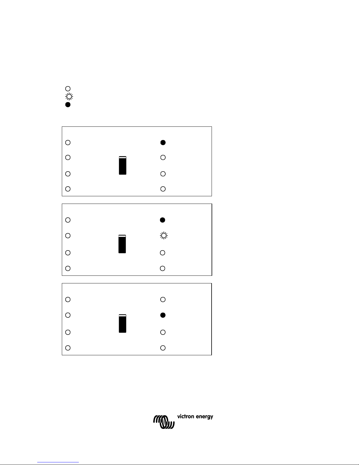
Inverter
Charger inverter
The inverter is on and supplies
power to the load.
mains on
on
inverter on
Bulk
overload
off
Absorption
low battery
charger
only
Float
temperature
Charger inverter
The nominal output of the
inverter is exceeded. The
“overload” LED flashes
mains on
on
inverter on
Bulk
overload
off
absorption
low battery
charger
only
Float
temperature
Charger inverter
The inverter is switched off due
to overload or short circuit.
mains on
on
inverter on
Bulk
overload
off
absorption
low battery
charger
only
Float
temperature
9
EN NL FR DE ES Appendix
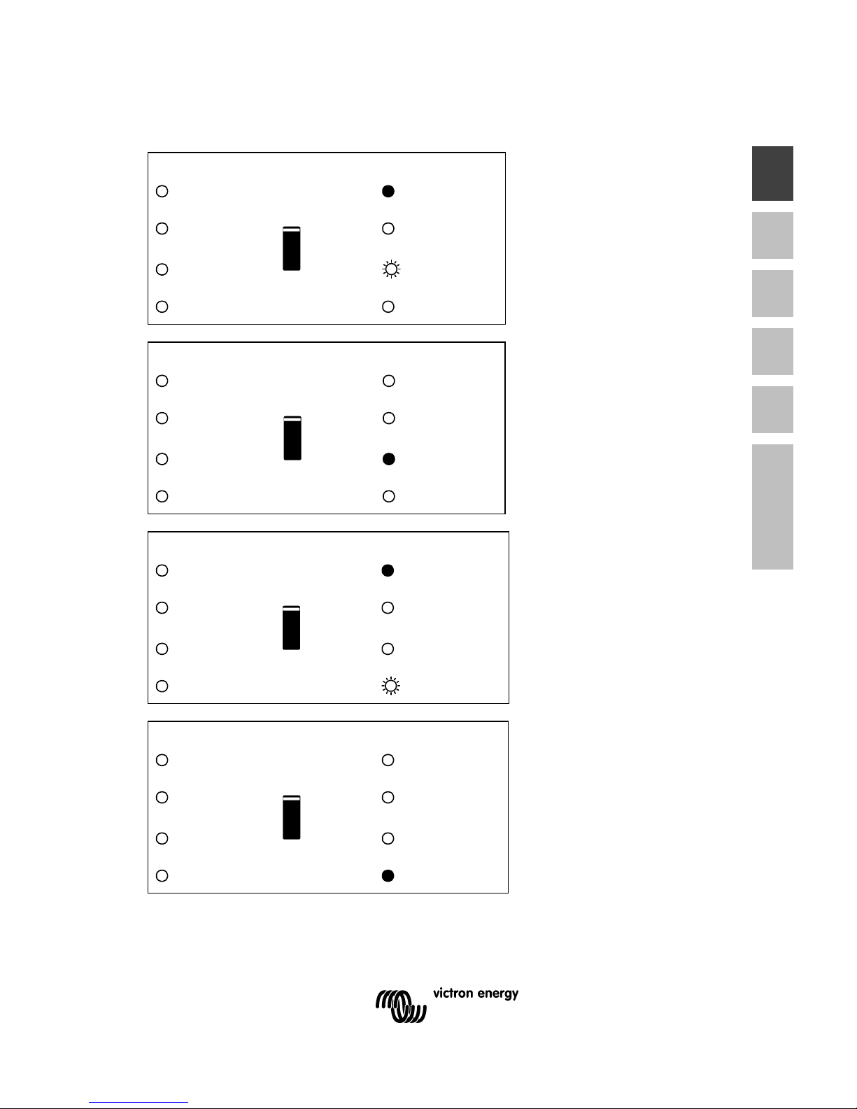
Charger inverter
The battery is almost fully
exhausted.
mains on
on
inverter on
Bulk
overload
off
absorption
low battery
charger
only
Float
temperature
Charger inverter
The inverter has switched off
due to low battery voltage.
mains on
on
inverter on
Bulk
overload
off
absorption
low battery
charger
only
Float
temperature
Charger inverter
The internal temperature is
reaching a critical level.
mains on
on
inverter on
Bulk
overload
off
absorption
low battery
charger
only
Float
temperature
Charger inverter
The inverter has switched off
due to the electronics
temperature being too high.
mains on
on
inverter on
Bulk
overload
off
absorption
low battery
charger
only
Float
temperature

10
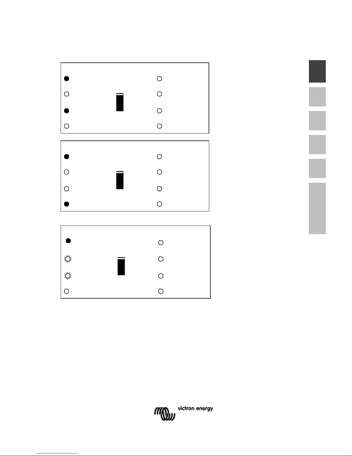
Charger inverter
-If the LEDs are flashing
alternately, the battery is nearly
exhausted and the nominal
output is exceeded.
-If "overload" and "low battery"
flash simultaneously, the ripple
voltage on the battery terminals
is too high.
mains on
on
inverter on
Bulk
overload
off
absorption
low battery
charger
only
Float
temperature
Charger inverter
The inverter switched off due to
excess ripple voltage on the
battery terminals.
mains on
on
inverter on
Bulk
overload
off
absorption
low battery
charger
only
Float
temperature
Battery Charger
Charger inverter
The AC input voltage is
switched through and the
charger operates in bulk mode.
mains on
on
inverter on
Bulk
overload
off
absorption
low battery
charger
only
Float
temperature
Charger
inverter
The mains voltage is switched
through and the charger is on.
The set absorption voltage,
however, has not yet been
reached. (BatterySafe mode)
mains on
on
inverter on
Bulk
overload
off
absorption
low battery
charger
only
Float
temperature
11
EN NL FR DE ES Appendix
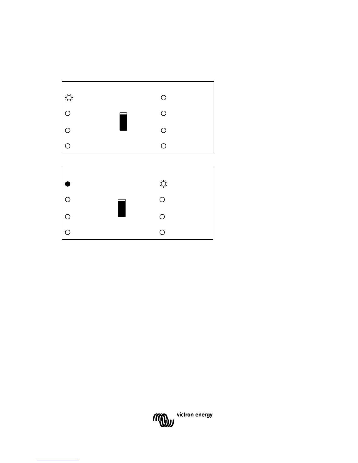
Charger inverter
The mains voltage is switched
through and the charger
operates in absorption mode.
mains on
on
inverter on
Bulk
overload
off
absorption
low battery
charger
only
Float
temperature
Charger inverter
The mains voltage is switched
through and the charger
operates in float mode.
mains on
on
inverter on
Bulk
overload
off
absorption
low battery
charger
only
Float
temperature
Charger inverter
The mains voltage is switched
through and the charger
operates in equalize mode.
mains on
on
inverter on
Bulk
overload
off
absorption
low battery
charger
only
Float
temperature
12
Special Indications
PowerControl
charger inverter
The AC input is switched
through. The AC output current
is equal to the preset
maximum input current. The
charge current is reduced to 0.
mains on
on
inverter on
bulk
overload
off
absorption
low battery
charger
only
float
temperature
Power Assist
charger inverter
The AC input is switched
through but the load requires
more current than the preset
maximum input current. The
inverter is switched on to
supply the required additional
current.
mains on
on
inverter on
bulk
overload
off
absorption
low battery
charger
only
float
temperature
13
EN NL FR DE ES Appendix
4. Installation
This product may only be installed by a qualified electrical engineer.
4.1 Contents of the box
• Phoenix MultiPlus.
• Manual.
• Suspension bracket
• Temperature sensor
• Warning sticker for battery charging
• Four fixing screws
• Fuse
4.2 Location
The product must be installed in a dry and well-ventilated area, as close as possible to
the batteries. There should be a clear space of at least 10 cm around the appliance for
cooling.
Excessively high ambient temperature will result in the following:
• Reduced service life.
• Reduced charging current.
• Reduced peak capacity, or shutdown of the inverter.
• Never position the appliance directly above the batteries.
The MultiPlus is suitable for wall mounting. For mounting purposes, a hook and two
holes are provided at the back of the casing (see appendix G). The device can be
fitted either horizontally or vertically. For optimal cooling, vertical fitting is preferred.
The interior of the product must remain accessible after installation.
Try and keep the distance between the product and the battery to a minimum in order
to minimize cable voltage losses.
For safety purposes, this product should be installed in a heat-resistant
environment. You should prevent the presence of e.g. chemicals, synthetic
components, curtains or other textiles, etc., in the immediate vicinity.
14
4.3 Requirements
• Philips screwdriver (PH2) for removing the front.
• Flat screwdriver (0.6x3.5) for connecting the AC leads.
• Isolated box spanner (13 mm) for securing the terminal nuts and the fuse.
• Two battery cables including battery terminals and cable ends.
• Three-wire cable.
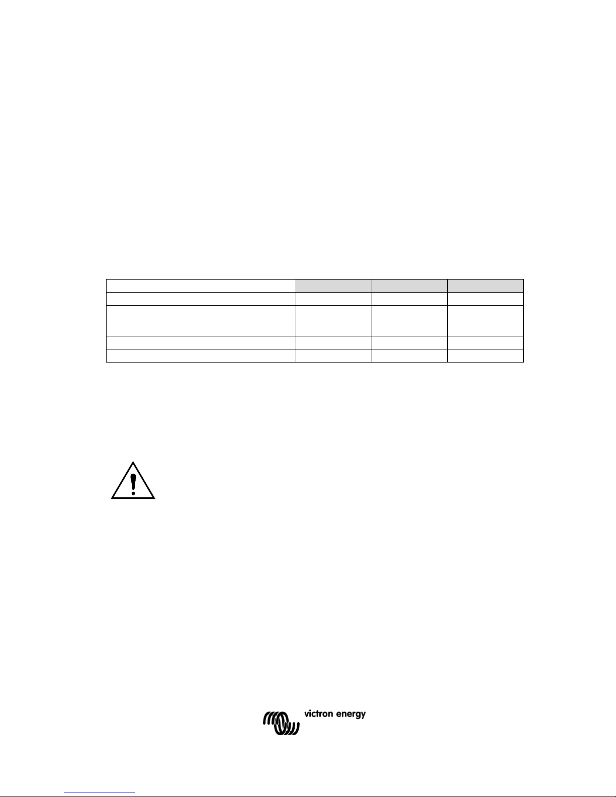
4.4 Connection of battery cables
In order to utilize the full capacity of the product, batteries with sufficient capacity and
battery cables with sufficient cross section should be used. See table.
12/3000/120 24/3000/70 48/3000/35
Recommended battery capacity (Ah) 400–1200 200–700 100–400
Recommended cross section (mm2)
0 – 5 m 90 50 35
5 – 10 m 120 90 70
Remark: Internal resistance is the important factor when working with low capacity
batteries. Please consult your supplier or the relevant sections of our book “Energy
Unlimited”, downloadable from our website.
Procedure
Proceed as follows to connect the battery cables:
Use an insulated box spanner in order to avoid shorting the battery.
Avoid shorting the battery cables.
• Undo the four screws at the front of the enclosure and remove the front panel.
• Connect the battery cables: the + (red) on the right and the - (black) on the left,
see Appendix 0.
• Reverse polarity connection (+ to – and – to +) will cause the “reversed polarity”
LED next to the terminal nuts to light up.
• Disconnect the cables and reconnect them correctly if the “reversed polarity" LED
is illuminated.
• Tighten the connections after positioning the fastening items supplied with the
product.
• Position the Mega fuse from the connection bag in position F4 and secure it,
using the fastening items supplied with the product.
• Secure the nuts tightly in order to reduce the contact resistance as much as
possible.
15
EN NL FR DE ES Appendix
4.5 Connection of the AC cabling
This is a Safety Class I product (supplied with a protective grounding
terminal). Uninterruptible protective grounding must be provided at the
AC input and/or output terminals and/or chassis grounding point
located externally on the product. See the following instructions:
The MultiPlus: the output neutral wire will automatically be bonded to
the chassis (with the output ground relay, see appendix) when no
external AC source is available (backfeed / safety relay open and product
runnig in inverter mode, see appendix). When an external AC source is
provided, the ground relay opens before closure of the backfeed / safety
relay. Once closed, the backfeed / safety relay ensures that the neutral to
ground bond is provided by the external AC source. This is to ensure
proper functioning of a GFCI to be installed in the AC output of the
Multi/MultiPlus.
- In a fixed (for example terrestrial) installation an uninterrupted chassis
ground may be provided by the AC input ground wire.
- In case of a mobile installation (connection to input AC with a shore power
cord), the ground connection is lost when the shore power cord is
unplugged. In this case the chassis of the product or the on - board section
of the input ground wire must be connected to the frame (of the vehicle) or
the ground plate or hull (of a boat).
- Marine applications: due to the potential for galvanic corrosion it is in
general not acceptable to connect the shore side ground to the ground
plate or hull of the boat. The proper and safe solution is to install an
isolation transformer.
The terminal block can be found on the printed circuit board, see Appendix 0. The
shore or mains cable must be connected to the Multi with the aid of a three-wire cable.
Use a three-wire cable with a flexible core and a cross section of 2.5 or 4 mm²
Procedure
Proceed as follows to connect the AC cables:
• The AC output cable can be connected directly to the terminal block "AC-out".
From left to right: “PE” (earth), “N” (neutral) and “L” (phase).
• The AC input cable can be connected to the terminal block “AC–in”.
From left to right: “PE” (earth), “N” (neutral) and “L” (phase).
4.6 Optional Connections
A number of optional connections are possible:
4.6.1 Second Battery
The MultiPlus has a connection for charging a starter battery. For connection see
Appendix 0.

16
4.6.2 Voltage Sense
Two sense wires may be connected to compensate possible battery cable losses
during charging. Use wires of at least 0.75mm2. For connection see Appendix 0.
4.6.3 Temperature Sensor
The temperature sensor supplied with the product may be used for temperaturecompensated charging (see Appendix 0). The sensor is isolated and must be mounted
on the batteries minus pole.
4.6.4 Remote Control
The product can be operated remotely in two ways.
• With an external switch.
• With a Phoenix Multi Control panel.
For connection of the switch see Appendix 0.
Observe the following when using an external switch:
• Only functions if the switch on the product is switched to the "on" position.
• Not to be connected if a remote control panel is connected.
For connection of the remote control panel, see Appendix 0.
Observe the following when using a remote control panel:
• Only functions if the switch on the product is switched to the "on" position.
4.6.5 External Relay
The maximum current that can be switched through from the AC input to the AC
output is 16 A (optional: 30 A). At more than 30 A an external contactor is needed:
please consult your supplier.
4.6.6 Parallel Connection
The MultiPlus can be connected in parallel with several identical devices. To this end,
a connection is established between the devices by means of standard RJ45 UTP
cables. The system (one or more Multi’s plus optional control panel) will require
subsequent configuration (see Section 5).
In the event of connecting MultiPlus units in parallel, the following requirements must
be met:
• A maximum of six units connected in parallel.
• Only identical devices with the same power ratings may be connected in parallel.
• Battery capacity should be sufficient.
• The DC connection cables to the devices must be of equal length and cross-section.
• If a positive and a negative DC distribution point is used, the cross-section of the connection
between the batteries and the DC distribution point must at least equal the sum of the
required cross-sections of the connections between the distribution point and the MultiPlus
units.
• Place the MultiPlus units close to each other, but allow at least 10 cm for ventilation
purposes under, above and beside the units.
• UTP cables must be connected directly from one unit to the other (and to the remote panel).
Connection/splitter boxes are not permitted.
• A battery-temperature sensor need only be connected to one unit in the system. If the
temperature of several batteries is to be measured, you can also connect the sensors of
other MultiPlus units in the system (with a maximum of one sensor per MultiPlus).

17
EN NL FR DE ES Appendix
Temperature compensation during battery charging responds to the sensor indicating the
highest temperature.
• Voltage sensing must be connected to the master (see Section 5.5.1.4).
• If more than three units are connected in parallel in one system, a dongle is required (see
Section 5).
• Only one remote control means (panel or switch) can be connected to the system.
4.6.7 Three-phase operation
The MultiPlus can also be used in 3-phase configuration. To this end, a connection
between the devices is made by means of standard RJ45 UTP cables (the same as
for parallel operation). The system (Multi’s plus an optional control panel) will require
subsequently configuration (see Section 5).
Pre-requisites: see Section 4.6.6.

18
5. Configuration
•
Settings may only be changed by a qualified electrical engineer.
• Read the instructions thoroughly before implementing changes.
• During setting of the charger, the AC input must be removed.
5.1 Standard settings: ready for use
On delivery, the MultiPlus is set to standard factory values. In general, these settings
are suitable for single-unit operation.
Warning: Possibly, the standard battery charging voltage is not suitable for
your batteries! Refer to the manufacturer's documentation, or to
your battery supplier!
Standard MultiPlus factory settings
Inverter frequency 50 Hz
Input frequency range 45 - 65 Hz
Input voltage range 180 - 265 VAC
Inverter voltage 230 VAC
Stand-alone / parallel / 3-phase stand-alone
AES (Automatic Economy Switch) off
Ground relay on
Charger on/ off on
Charging characteristics four-stage adaptive with
BatterySafe mode
Charging current 75% of the maximum charging
current
Battery type Victron Gel Deep Discharge (also
suitable for Victron AGM Deep
Discharge)
Automatic equalisation charging off
Absorption voltage 14.4 / 28.8 / 57.6 V
Absorption time up to 8 hours (depending on bulk
time)
Float voltage 13.8 / 27.6 / 55.2 V
Storage voltage 13.2V (not adjustable)
Repeated absorption time 1 hour
Absorption repeat interval 7 days
Bulk protection on
AC input current limit 30A or 16A depending on model
(current limit for PowerControl and
PowerAssist functions)
UPS feature on
Dynamic current limiter off
WeakAC off
BoostFactor 2
Multi-functional relay alarm function

19
EN NL FR DE ES Appendix
VirtualSwitch controls the multi-functional relay
PowerAssist on
5.2 Explanation of settings
Settings that are not self-explanatory are described briefly below. For further
information, please refer to the help files in the software configuration programs (see
Section 5.3).
Inverter frequency
Output frequency if no AC is present at the input.
Adjustability: 50Hz; 60Hz
Input frequency range
Input frequency range accepted by the MultiPlus. The MultiPlus synchronises within
this range with the AC input frequency. The output frequency is then equal to the input
frequency.
Adjustability: 45 – 65 Hz; 45 – 55 Hz; 55 – 65 Hz
Input voltage range
Voltage range accepted by the MultiPlus. The MultiPlus synchronises within this range
with the AC input voltage. The output voltage is then equal to the input voltage.
Adjustability: Lower limit: 180 - 230V
Upper limit: 230 - 270V
Inverter voltage
Output voltage of the MultiPlus in battery operation.
Adjustability: 210 – 245V
Stand-alone / parallel operation / 2-3 phase setting
Using several devices, it is possible to:
• increase total inverter power (several devices in parallel)
• create a split-phase system (only for MultiPlus units with 120V output
voltage)
• create a 3-phase system.
To this end, the devices must be mutually connected with RJ45 UTP cables.
Standard device settings, however, are such that each device operates in stand-alone
operation. Reconfiguration of the devices is therefore required.
AES (Automatic Economy Switch)
If this setting is turned ‘on’, the power consumption in no-load operation and with low
loads is decreased by approx. 20%, by slightly 'narrowing' the sinusoidal voltage. Not
adjustable with DIP switches. Applicable in stand-alone configuration only.

20
Ground relay (see appendix B)
With this relay (H), the neutral conductor of the AC output is grounded to the chassis
when the back feed safety relay is open. This ensures the correct operation of earth
leakage circuit breakers in the output.
If a non-grounded output is required during inverter operation, this function must be
turned off. (See also Section 4.5)
Not adjustable with DIP switches.
Charging characteristics
The standard setting is ‘Four-stage adaptive with BatterySafe mode’. See Section 2
for a description.
This is the best charging characteristic. See the help files in the software configuration
programs for other features.
‘Fixed’ mode can be selected with DIP switches.
Battery type
The standard setting is the most suitable for Victron Gel Deep Discharge, Gel Exide
A200, and tubular plate stationary batteries (OPzS). This setting can also be used for
many other batteries: e.g. Victron AGM Deep Discharge and other AGM batteries, and
many types of flat-plate open batteries. Four charging voltages can be set with DIP
switches.
Absorption time
This depends on the bulk time (adaptive charging characteristic), so that the battery is
optimally charged. If the ‘fixed’ charging characteristic is selected, the absorption time
is fixed. For most batteries, a maximum absorption time of eight hours is suitable. If an
extra high absorption voltage is selected for rapid charging (only possible for open,
flooded batteries!), four hours is preferable. With DIP switches, a time of eight or four
hours can be set. For the adaptive charging characteristic, this determines the
maximum absorption time.
Storage voltage, Repeated Absorption Time, Absorption Repeat Interval
See Section 2. Not adjustable with DIP switches.
Bulk Protection
When this setting is ‘on’, the bulk charging time is limited to 10 hours. A longer
charging time could indicate a system error (e.g. a battery cell short-circuit). Not
adjustable with DIP switches.
AC input current limit
These are the standard current limit settings for which PowerControl and PowerAssist
come into operation. The standard setting is 30A. In case of models with max. 16A
feed through current, the maximum is automatically reduced to 16A.
See Section 2, the book 'Energy Unlimited', or the many descriptions of this unique
feature on our website www.victronenergy.com .

21
EN NL FR DE ES Appendix
UPS feature
If this setting is ‘on’ and AC on the input fails, the MultiPlus switches to inverter
operation practically without interruption. The MultiPlus can then be used as an
Uninterruptible Power Supply (UPS) for sensitive equipment such as computers or
communication systems.
The output voltage of some small generator sets is too unstable and distorted for
using this setting – the MultiPlus would continually switch to inverter operation. For
this reason, the setting can be turned off. The MultiPlus will then respond less quickly
to AC input voltage deviations. The switchover time to inverter operation is
consequently slightly longer, but most equipment (computers, clocks or household
equipment) is not adversely impacted.
Recommendation: Turn the UPS feature off if the MultiPlus fails to synchronise, or
continually switches back to inverter operation.
Dynamic current limiter
Intended for generators, the AC voltage being generated by means of a static inverter
(so-called ‘inverter’ generators). In these generators, rpm is down-controlled if the load
is low: this reduces noise, fuel consumption and pollution. A disadvantage is that the
output voltage will drop severely or even completely fail in the event of a sudden load
increase. More load can only be supplied after the engine is up to speed.
If this setting is ‘on’, the MultiPlus will start supplying extra power at a low generator
output level and gradually allow the generator to supply more, until the set current limit
is reached. This allows the generator engine to get up to speed.
This setting is also often used for ‘classical’ generators that respond slowly to sudden
load variation.
WeakAC
Strong distortion of the input voltage can result in the charger hardly operating or not
operating at all. If WeakAC is set, the charger will also accept a strongly distorted
voltage, at the cost of greater distortion of the input current.
Recommendation: Turn WeakAC on if the charger is hardly charging or not charging
at all (which is quite rare!). Also turn on the dynamic current limiter simultaneously,
and reduce the maximum charging current to prevent overloading the generator if
necessary.
Not adjustable with DIP switches.
BoostFactor
Change this setting only after consulting with Victron Energy or with an engineer
trained by Victron Energy!
Not adjustable with DIP switches.

22
Multi-functional relay
By default, the multi-functional relay is set as an alarm relay, i.e. the relay will deenergise in the event of an alarm or a pre-alarm (inverter almost too hot, ripple on the
input almost too high, battery voltage almost too low). Not adjustable with DIP
switches.
VirtualSwitch
The VirtualSwitch is a software function in the MultiPlus microprocessor. The inputs of
this function are parameters that can be selected with VEConfigure (e.g. certain
alarms or voltage levels). The output is binary (0 or 1). The output can be connected
to a binary microprocessor output (e.g. the multi-functional relay, or the relay in one of
the AC inputs).
If connected to the multi-functional relay, and with battery voltage and time as input
values, for example, the VirtualSwitch can be configured to supply a generator starting
signal.
If connected to an AC input relay, and with battery voltage and time as input, for
example, the connected mains supply can be interrupted.
Application: autonomous operation when the grid fails
Houses or buildings with solar panels or a combined micro-scale heating and power
plant or other sustainable energy sources have a potential autonomous energy supply
which can be used for powering essential equipment (central heating pumps,
refrigerators, deep freeze units, Internet connections, etc.) during a power failure. A
problem is however that grid connected sustainable energy sources drop out as soon
as the grid fails. With a MultiPlus and batteries, this problem can be solved in a simple
manner: the MultiPlus can replace the grid during a power failure. When the
sustainable energy sources produce more power than needed, the MultiPlus will use
the surplus to charge the batteries; in the event of a shortfall, the MultiPlus will supply
additional power from the battery.

23
EN NL FR DE ES Appendix
5.3 Configuration by computer
All settings can be changed by means of a computer or with a VE.Net panel (except
for the multi-functional relay and the VirtualSwitch when using VE.Net).
The most common settings (including parallel and 3-phase operation) can be changed
by means of DIP switches (see Section 5.5).
For changing settings with the computer, the following is required:
- VEConfigureII software. You can download the VEConfigureII software free
of charge at www.victronenergy.com .
- A RJ45 UTP cable and the MK2.2b RS485-to-RS232 interface. If your
computer has no RS232 connection, but does have USB, you will also need
a RS232-to-USB interface cable. Both are available from Victron Energy.
5.3.1 VE.Bus Quick Configure Setup
VE.Bus Quick Configure Setup is a software program with which systems with a
maximum of three Multi’s (parallel or three phase operation) can be configured in a
simple manner. VEConfigureII forms part of this program.
You can download the software free of charge at www.victronenergy.com .
For connection to your computer, a RJ45 UTP cable and the MK2.2b RS485-to-
RS232 interface is required.
If your computer does not have a RS232 connection but is equipped with USB, you
will also need a RS232-to-USB interface cable. Both are available from Victron
Energy.
5.3.2 VE.Bus System Configurator and dongle
For configuring advanced applications and/or systems with four or more Multi’s,
VE.Bus System Configurator software must be used. You can download the
software at www.victronenergy.com . VEConfigureII forms part of this program.
You can configure the system without a dongle, and use it for 15 minutes (as a
demonstration facility). For permanent use, a dongle – available at additional charge –
is required.
For connection to your computer, a RJ45 UTP cable and the MK2.2b RS485-to-
RS232 interface is required.
If your computer does not have a RS232 connection but is equipped with USB, you
will also need a RS232-to-USB interface cable.
Both are available from Victron Energy.
5.4 Implementing settings with a VE.Net panel
To this end, a VE.Net panel and the VE.Net to VE.Bus converter is required.
With VE.Net you can set all parameters, with the exception of the multi-functional relay
and the VirtualSwitch.

24
5.5 Configuration with DIP switches
A number of settings can be changed using DIP switches (see appendix A, position
M).
This is done as follows:
Turn the Multi on, preferably unloaded en without AC voltage on the inputs. The Multi
will then operate in inverter mode.
Step 1: Setting the DIP switches for:
- the required current limitation of the AC input.
- AES (Automatic Economy Switch)
- limitation of the charging current.
- selection of stand-alone, parallel or 3-phase operation.
To store the settings after the required values have been set: press the 'Up' button for
2 seconds (upper button to the right of the DIP switches, see appendix A, position K).
You can now re-use the DIP switches to apply the remaining settings (step 2).
Step 2: other settings
To store the settings after the required values have been set: press the 'Down' button
for 2 seconds (lower button to the right of the DIP switches). You can now leave the
DIP switches in the selected positions, so that the ’other settings’ can always be
recovered.
Remarks:
- The DIP switch functions are described in 'top to bottom' order. Since the uppermost
DIP switch has the highest number (8), descriptions start with the switch numbered 8.
- In parallel mode or 3-phase mode, not all devices require all settings to be made
(see section 5.5.1.4).
For parallel or 3-phase mode, read the whole setting procedure and make a note of
the required DIP switch settings before actually implementing them.
5.5.1 Step 1
5.5.1.1 Current limitation AC input (default: 16A for models with max. 16A feed
through current, and 30A for models with max. 30A feed through current)
If the current demand (Multi load + battery charger) threatens to exceed the set
current, the Multi will first reduce its charging current (PowerControl), and
subsequently supply additional power from the battery (PowerAssist), if needed.
The AC input current limit can be set to eight different values by means of DIP
switches.
With a Phoenix Multi Control Panel, a variable current limit can be set for the AC input.
Remark: With a Duo Control Panel and an external AC change-over switch two
different limits can be set, for two AC sources, for example a shore connection and a
generator.

25
EN NL FR DE ES Appendix
Procedure
The AC input current limit can be set using DIP switches ds8, ds7 and ds6 (default
setting: 30A, automatically limited to 16A in 16A models).
Procedure: set the DIP switches to the required value:
ds8 ds7 ds6
off off off = 4A (0,9kVA at 230V)
off off on = 6A (1,4kVA at 230V)
off on off = 10A (2.3kVA at 230V)
off on on = 12A (2.8kVA at 230V)
on off off = 16A (3.7kVA at 230V)
on off on = 20A (4.6kVA at 230V)
on on off = 25A (5,7kVA at 230V)
on on on = 30A (6.9kVA at 230V)
Remark: Manufacturer-specified continuous power ratings for small
generators are sometimes inclined to be rather optimistic. In that
case, the current limit should be set to a much lower value than
would otherwise be required on the basis of manufacturer-specified
data.
5.5.1.2 AES (Automatic Economy Switch)
Procedure: set ds5 to the required value:
ds5
off = AES off
on = AES on
5.5.1.3 Charging current limitation (default setting 75%)
For maximum battery life, a charging current of 10% to 20% of the capacity in Ah
should be applied.
Example: optimal charging current of a 24V/500Ah battery bank: 50A to 100A.
The temperature sensor supplied automatically adjusts the charging voltage to the
battery temperature.
If faster charging – and a subsequent higher current – is required:
- The temperature sensor supplied should always be fitted, since fast charging can
lead to a considerable temperature rise of the battery bank. The charging voltage will
be adapted to the higher temperature (i.e. lowered) by means of the temperature
sensor.
- The bulk charging time will sometimes be so short that a fixed absorption time would
be more satisfactory (‘fixed’ absorption time, see ds5, step 2).
Procedure
The battery charging current can be set in four steps, using DIP switches ds4 and ds3
(default setting: 75%).
ds4 ds3
off off = 25%
off on = 50%
on off = 75%
on on = 100%
 Loading...