

Victron energy Phoenix Compact 24/1200, Phoenix Compact 24/1600, Phoenix Compact 12/1200, Phoenix Compact 12/1600 User Manual

Manual
EN
Handleiding
NL
Manue
l
FR
Anleitung
DE
Manual
ES
Appendix
Phoenix Inverter Compact
12 | 1200 230V 24 | 1200 230V
12 | 1600 230V 24 | 1600 230V


Copyrights 2008 Victron Energy B.V.
All Rights Reserved
This publication or parts thereof may not be reproduced in any form, by any method, for any purpose.
For conditions of use and permission to use this manual for publication in other than the English
language, contact Victron Energy B.V.
VICTRON ENER GY B.V. MAKES NO WARRANTY, EITHER EXPRESSED O R IMPLIED, INCL U D IN G
BUT NOT LIMITED TO ANY IMPLIED WARRANTIES OF MERCHANT ABILITY O R FITNESS FOR A
PARTICULAR PURPOSE, REGARDING THESE VICTRON ENERGY PRODUCTS AND MAKES
SUCH VICTRON ENERGY PRODUCTS AVAILABLE SOLELY ON AN “AS IS” BASIS.
IN NO EVENT SHALL VICTRON EN ER G Y B.V. BE LIABLE TO ANYONE FOR SPECIAL,
COLLATER AL , IN C ID ENTAL, OR CONSEQUENTIAL DAMAGES IN CONNECTION WITH OR
ARISING OUT OF PURCHASE OR USE OF THESE VICTRON ENERGY PRO DUCT S. THE SOLE
AND EXCLUSIVE LIABILITY TO VICTRON ENERGY B.V., REGARDLESS OF THE FORM OF
ACTION, SHALL NOT EXCEED THE PURCHASE PRICE OF THE VICTRON ENERGY PRODUCTS
DESCRIBED HERE IN.
Victron Energy B.V. reserves the right to revise and improve its products as it sees fit. This publication
describes the state of this product at the time of its publication and may not reflect the product at all
tim es in the fut ure


1
EN NL FR DE ES Appendix
1. SAFETY INSTRUCTIONS
General
Please familiarize yourself with the safety features and instruct i ons by first reading the
documentation supplied with this product before using the equipment. This product has
been designed and tested in accordance with international standards. The equipment
must be used exclusively for the purpose for which it was designed.
WARNING: ELECTRIC SHOCK HAZARD.
The product is used in conjunction with a permanent energy source (battery). Input and/or
output terminals may still be dangerously energized, even when the equipm ent is
switched off. Always switch off the AC supply and the battery before carrying out
maintenance or servicing the product.
The product has no internal user-serviceable components. Do not remove the front plate
or operate the product if any panels have been removed. All servicing must be
undertaken by qualified personnel.
Never use the product where there is a risk of gas or dust explosions. Consult the battery
manufacturer's information to ascertain that the product is i ntended for use i n conjunction
with the battery. Always comply with the battery manufacturer's safety instructions.
WARNING: Do not lift heavy loads without assistance.
Installation
Read the installation instructions in the installat i on manual before instal ling t he equipment.
This is a Safety Class I product (supplied with a protective grounding terminal). The chassis
must be grounded. A grounding point is located on the outside of the product. Whenever it is
likely that the grounding prot ection has been damaged, the product must be turned off and
secured against unintended operation; please contact qualified servic e st aff.
Ensure that the DC and AC input cables are fused and fitted with circuit breakers. Never
replace a safety component with a different type. Consult the manual to determine the correct
component.
Before applying power, ensure that the available power source matches the configurati on
settings of the product as described in the manual.
Ensure that the equipment is used under the correct ambient conditions. Never operate the
product in a wet or dusty environment. Ensure there is adequate free space for ventilation
around the product and check that the ventilation vents are not blocked.
Ensure that the required system voltage does not exceed the product's capacity.

2
Transport and Storage
Ensure that the mains power and battery leads have been disconnected before storing or
transporting the product.
No liability can be accepted for any transport damage if the equipment is shipped in nonoriginal packaging.
Store the product in a dry environment; the storage temperature must be between -20°C and
60°C.
Consult the battery manufacturer's manual in respect of transport, storage, charging,
recharging and disposal of the battery.

3
EN NL FR DE ES Appendix
2. DESCRIPTION
2.1 General
SinusMax - Superior engineering
Developed for professional duty, the Phoenix range of inverters is suitable for the widest
range of applications. The design criteria have been to produce a true sine wave inverter
with optimised efficiency but without compromise in performance. Employing hybrid HF
technology, the result is a top quality product with compact dimensions, light in weight
and capable of supplying power, problem-free, to any load.
Extra start-up pow er
A unique feature of the SinusMax technology is very high start-up power. Conventional
high frequency technology does not offer such extreme performance. Phoenix inverters,
however, are well suited to power up difficult loads such as compressors, electric motors
and similar appliances.
Parallel and 3-phase operation capability
Up to 6 inverters can operate in parallel to achieve higher power output.
Operation in 3-phase configuration is also possible.
To transfer the load to another AC source: the automatic transfer switch
If an automatic transfer switch is required, we recommend to using the MultiPlus or
Quattro instead. The switch is included in these products and the charger function of the
MultiPlus/Quattro can be disabled. Computers and other electronic equipment will conti nue to
operate without disruption because the MultiPlus/Quatt ro features a very short s witchover
time (less than 20 milliseconds).
Programmable relay
The Phoenix Inverter is equipped with a programmable relay, which by default is set as an
alarm relay. The relay can be programmed for all kinds of other applications however, for
example as a starter relay for a generating set.
Programmable with DIP switches, VE.Net panel or personal computer
The Phoenix Inverter is supplied ready for use. Three features are available for changing
certain settings if desired:
- The most important settings can be changed in a very simple manner, using DIP switches.
- All settings, with exception of the programmable relay, can be changed with a VE.Net panel.
- All settings can be changed with a PC and free of charge software, downloadable from our
website www.victronenergy.com.
4
3. OPERATION
3.1 On/Off Switch
When switched to "on", the product is fully functional. The inverter will come into operation
and the LED "inverter on" will light up.
3.2 Remote control
Remote control is possible with a simple on/off switch or with a Phoenix Inverter Control
panel.
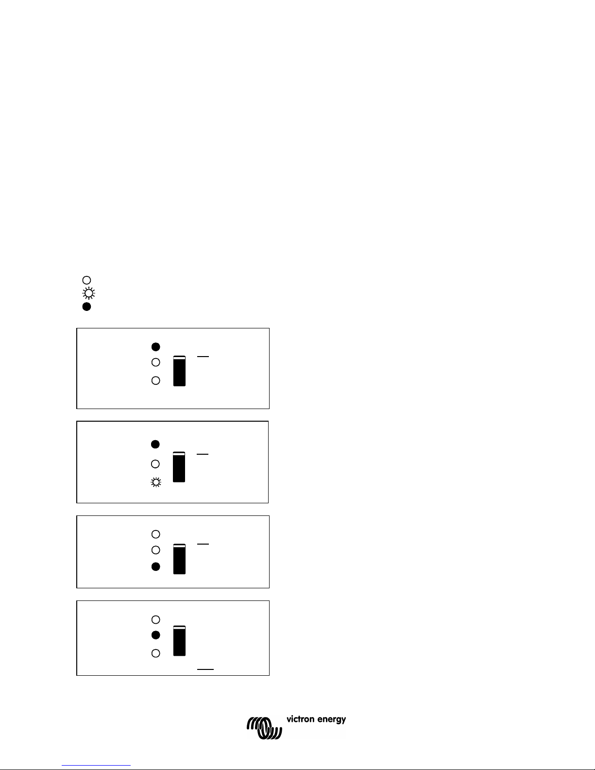
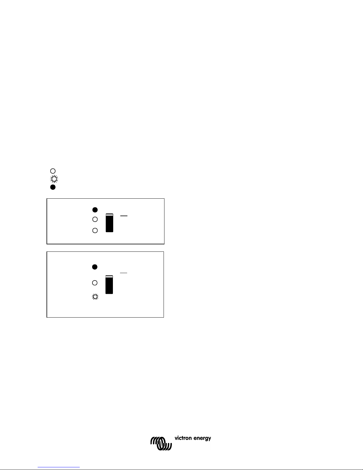
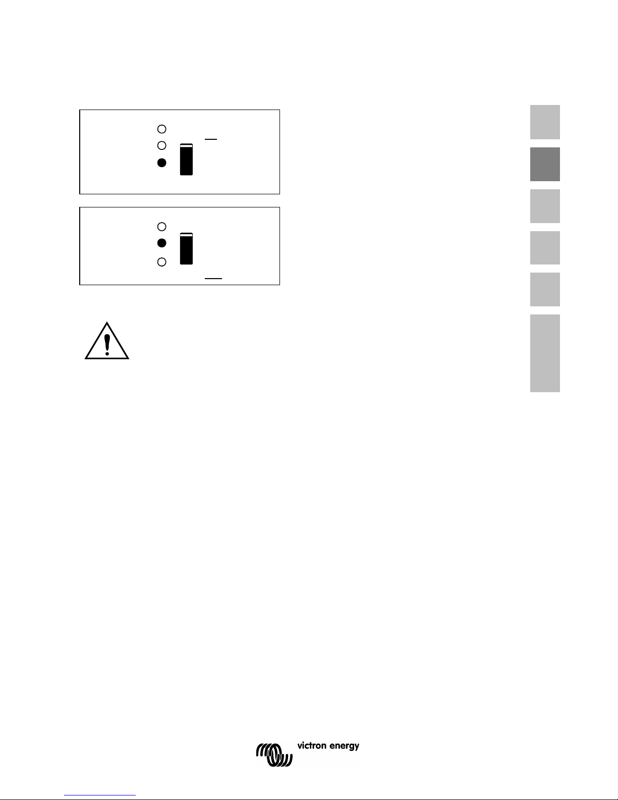
3.3 LED Indications
LED off
LED flashes
LED illuminated
The inverter is switched on and supplies
power to the load. Battery operation.
inverter
on
eco mode
off
alarm
eco
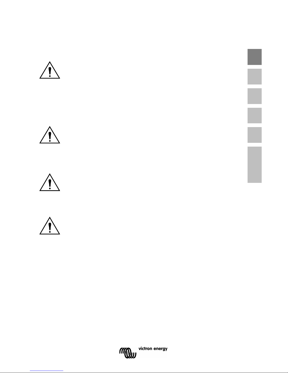
The inverter is switched on and supplies
power to the load.
Pre alarm: overload, or
battery voltage low, or
inverter temperature high
inverter
on
eco mode
off
alarm
eco
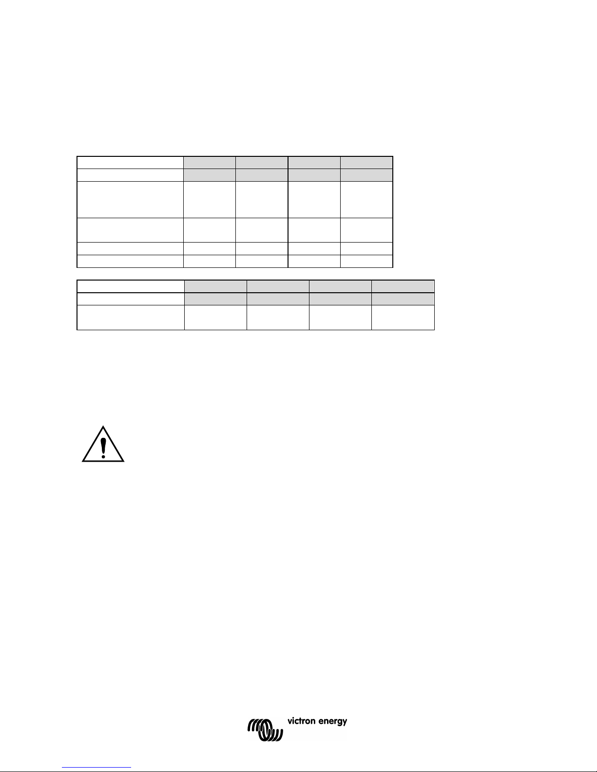
The inverter is switched off.
Alarm: overload, or
battery voltage low, or
inverter temperature hig, or
DC ripple voltage on battery
terminal was too high.
inverter
on
eco mode
off
alarm
eco
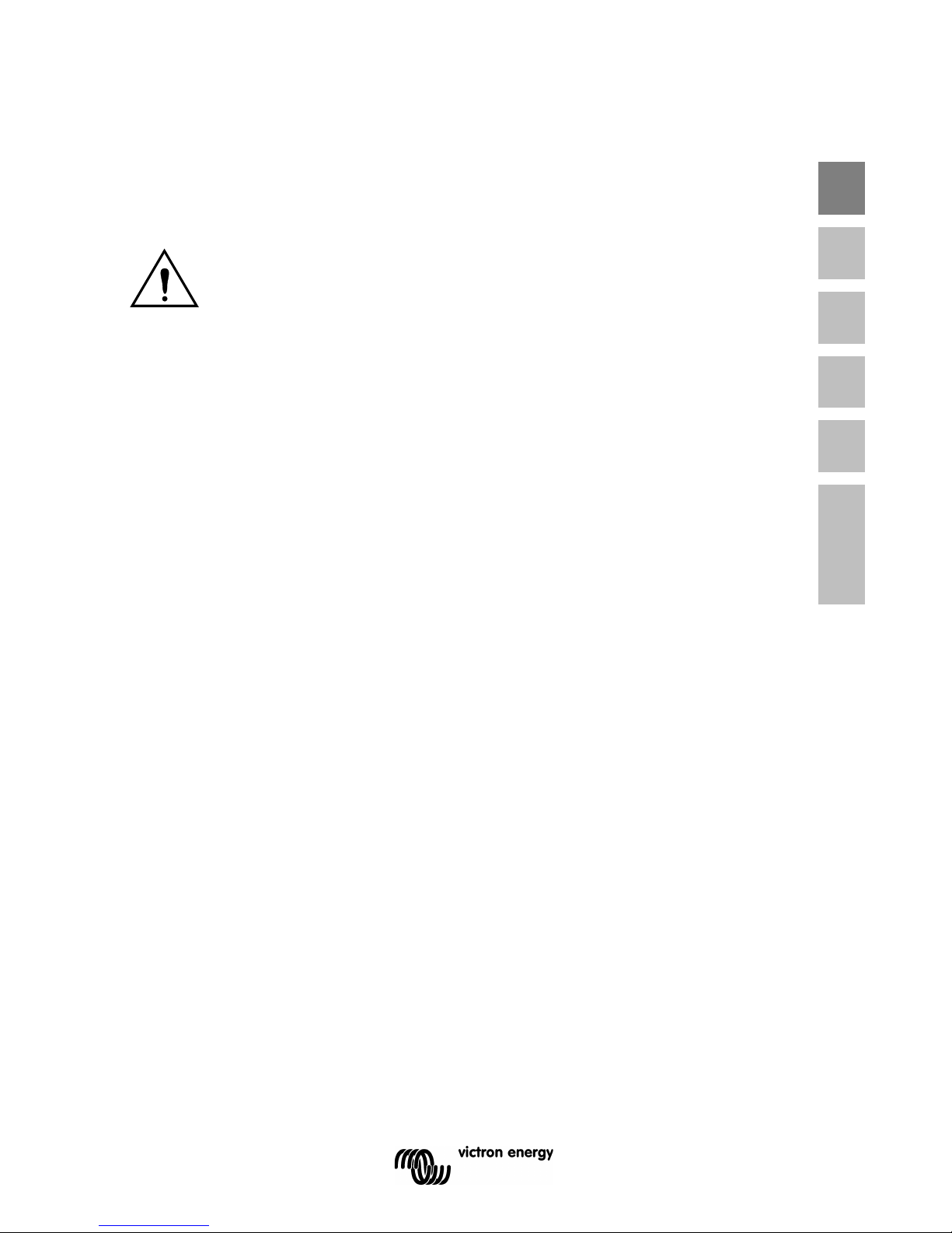
The inverter is switched on ”eco mode”
and supplies power to the load.
inverter
on
eco mode
off
alarm
eco
5
EN NL FR DE ES Appendix
4. INSTALLATION
4.1 Location
The product must be installed in a dry and well-ventilated area, as close as possible to
the batteries. There should be a clear space of at least 10cm around the appliance for
cooling.
Excessively high ambient temperature will result in the following:
Reduced service life.
Reduced charging current.
Reduced peak capacity, or shutdown of the inverter.
Never mount the appliance directly above the batteries.
The product is suitable for wall mounting. For mounting see appendix A.
The appliance can be mounted horizontally as well as vertically; vertical mounting is
preferable. The vertical position offers optimum cooling.
Try and keep the distance between the product and the battery to a minimum in order to
minimize cable voltage losses.
For safety purposes, this product should be installed in a heat-resistant
environment if it is used with equipment where a substantial amount of power is
to be converted. You should prevent the presence of e.g. chemicals, synthetic
components, curtains or other textiles, etc., in the immediate vicinity.
This product should be installed by a qualified electrician.
The interior of the product must remain accessible after installation.
6
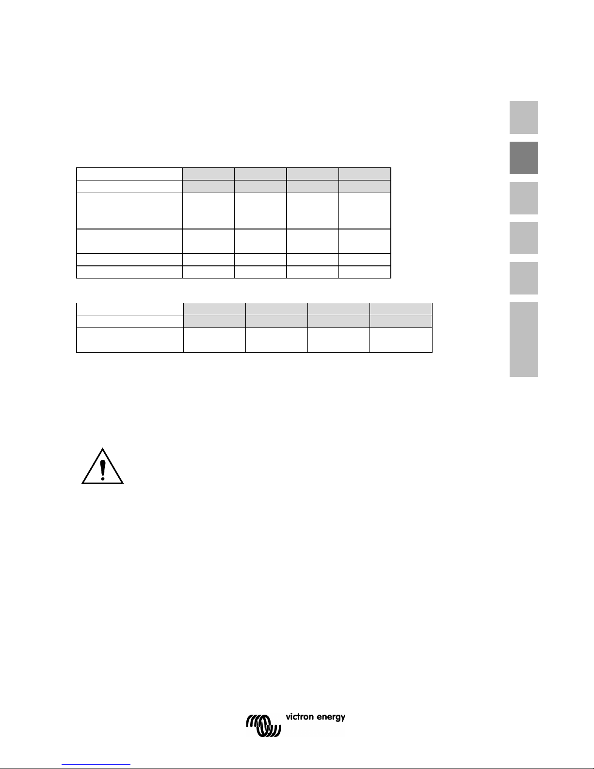
4.2 Connection of Battery cables
In order to fully utilize the full capacity of the product, batteries with sufficient capaci t y and
battery cables with sufficient cross section should be used. See table.
24/1200
24/1600
12/1200
12/1600
Preassembled
cable length 1.5 m
(mm2)
16 25 25 35
Recommended
cross section (mm2)
1,5 1 5 m
25
35
50
70
5 10 m
50
70
100
140
24/1200
24/1600
12/1200
12/1600
Recommended
battery capacity (Ah)
40 – 400 100 – 400 150 – 700 200 – 700
Remark: Internal resistance is the important factor when working with low capacity batteries.
Please consult your supplier or the relevant sections of our book “electricit y on board”,
downloadable from our website.
Procedure
Proceed as follows to connect the battery cables:
Use an insulated box spanner in order to avoid shorting the battery.
Avoid shorting the battery cables.
Connect the battery cables: the + (red) and the - (black), to the battery see appendix A.
Reverse polarity connection (+ to – and – to +) will cause damage to the product. (Safety fuse
inside the Phoenix Inverter Compact can be damaged)
Secure the nuts tightly in order to reduce the contact resistance as much as possible.
7
EN NL FR DE ES Appendix
4.3 Connection of the AC cabling
This is a Safety Class I product (supplied with a protective grounding
terminal).
The neutral wire of the AC output of this inverter is connected to the
chassis.
This is to ensure proper functioning of a GFCI (or RCCB) to be installed in the
AC output of the Inverter.
The chassis of the product must be connected toground, to the frame (of a
vehicle) or the ground plate or hull (of a boat).
Procedure
The AC output cable can be connected directly to the male-connector at the bottom of the
enclosure. (the connector pulls out!)
The terminal points are indicated clearly. From left to right: “N” (neutral), earth, and “L1”
(phase).
Use a three-wire cable with a flexible core and a cross section of 1.5 or 2.5 mm².
4.4 Optional Connections
A number of optional connections are possible:
4.4.1 Remote on/off switch & remote Control panel
The product can be remotely controlled in two ways.
- With an external switch (connection terminal H, see appendix A). Operates only if the switch
on the Inverter is set to “on”.
- With a Phoenix Inverter Control panel (connected to one of the two RJ48 sockets C, see
appendix A). Operates only if the switch on the inverter is set to “on”.
Only one remote control can be connected, i.e. either a switch or a remote control
panel.
4.4.2. Programmable relay
The inverters are equipped with a multi-functional relay that by default is programmed as an
alarm relay. (VEConfigure software needed to change relay functionality).

8
4.4.3 Parallel Connection
The inverters can be connected in parallel with several identical devices. To this end, a
connection is established between the devices by means of standard RJ45 UTP cables. The
system (one or more inverters plus optional control panel) will require subsequent
configuration (see Section 5).
In the event of connecting inverters in parallel, the following requirements must be met:
- A maximum of six units connected in parallel.
- Only identical devices may be connected in parallel.
- The DC connection cables to the devices must be of equal length and cross-section.
- If a positive and a negative DC distribution point is used, the cross-section of the connection between the
batteries and the DC distribution point must at least equal the sum of the required cross-sections of the
connections between the distribution point and the inverters.
- Place the inverters close to each other, but allow at least 10 cm for ventilation purposes under, above and
beside the units.
- UTP cables must be connected directly from one unit to the other (and to the remote panel).
Connection/s pli tt er bo xes are not permitted .
- Only one remote control means (panel or switch) can be connected to the system.
4.4.4 Three-phase operation
The Phoenix Inverter can also be used in 3-phase configuration. To this end, a connection
between the devices is made by means of standard RJ45 UTP cables (the same as for
parallel operation). The system (Inverters plus an optional control panel) will require
subsequently configuration (see Section 5).
Pre-requisites: see Section 4.4.3.
Near the connection terminals an LED illuminates when the relay is activated (refer to S, see
appendix A)

9
EN NL FR DE ES Appendix
5. CONFIGURATION
5.1 Standard settings: ready for use
On delivery, the Phoenix inverter is set to standard factory values. In general, these
settings are suitable for stand-alone operation.
Standard factory settings
Inverter frequency 50 Hz
Inverter voltage 230 VAC
Stand-alone / parallel / 3-phase stand-alone
Search mode off
Programmable relay alarm function
5.2 Explanation of settings
Inverter frequency
Output frequency
Adjustability: 50Hz; 60Hz
Inverter voltage
Adjustability: 210 – 245V
Stand-alone / parallel operation / 2-3 phase setting
Using several devices, it is possible to:
- Increase total inverter power (several devices in parallel).
- Create a split-phase system.
- Create a 3-phase system.
The standard product settings are for standalone operation. For parallel, three phase or split
phase operation see section 4.4.3 and 4.4.4.
Settings may only be changed by a qualified engineer.
Carefully read the instructions before changes are made.
Batteries should be placed in a dry and well-ventilated area during charging.

10
Search Mode (Applicable in stand-alone configuration only)
If search mode is ‘on’, the power consumption in no-load operation is decreased by approx.
70%. In this mode the Compact, when operating in inverter mode, is switched off in case of no
load or very low load, and switches on every two seconds for a short period. If the output
current exceeds a set level, the inverter will continue to operate. If not, the inverter will shut
down again.
The Search Mode can be set with a DIP switch.
The Search Mode “shut down” and “remain on” load levels can be set with VEConfigure.
The standard settings are:
Shut down: 40 Watt (linear load).
Turn on: 100 Watt (linear load).
AES (Automatic Economy Switch)
Instead of the search mode, the AES mode can also be chosen (with help of VEConfigure
only).
If this setting is turned ‘on’, the power consumption in no-load operation and with low loads is
decreased by approx. 20%, by slightly 'narrowing' the sinusoidal voltage.
Not adjustable with DIP switches.
Applicable in stand-alone c onfigurat i on onl y.
Programmable relay
By default, the programmable relay is set as an alarm relay, i.e. the relay will de-energise in
the event of an alarm or a pre-alarm (inverter almost too hot, ripple on the input almost too
high, battery voltage almost too low).
Not adjustable with DIP switches.
Near the connection terminals an LED illuminates when the relay is activated (refer to S, see
appendix A)

11
EN NL FR DE ES Appendix
5.3 Configuration by computer
All settings can be changed by means of a computer or with a VE.Net panel (except for
the multi-functional relay and the VirtualSwitch when using VE.Net ).
Some settings can be changed with DIP switches (see Section 5.2).
For changing settings with the computer, the following is required:
- VEConfigure3 software: can be downloaded free of charge at www.victronenergy.com.
- A RJ45 UTP cable and the MK2.2b RS485-to-RS232 interface. If the computer has no
RS232 connection, but does have USB, a RS232-to-USB interface cable is needed.
Both are available from Victron Energy.
5.3.1 VE.Bus Quick Configure Setup
VE.Bus Quick Configure Setup is a software program with which one Compact unit or
systems with a maximum of three Compact units (parallel or three phase operation) can
be configured in a simple manner. VEConfigure3 forms part of this program .
The software free can be downloaded free of charge at www.victronenergy.com.
For connection to the computer, a RJ45 UTP cable and the MK2.2b RS485-to-RS232
interface is required.
If the computer has no RS232 connection, but does have USB, a RS232-to-USB
interface cable is needed. Both are available from Victron Energy.
5.3.2 VE.Bus System Configurator and dongle
For configuring advanced applications and/or systems with four or more inverters,
VE.Bus System Configurator software must be used. The software can be downloaded
free of charge at www.victronenergy.com. VEConfigure3 forms part of this program.
The system can be configured without a dongle, and will be fully functional during 15 minutes
(as a demonstration facility). For permanent use, a dongle – available at additional charge – is
required.
For connection to the computer, a RJ45 UTP cable and the MK2.2b RS485-to-RS232
interface is required.
If the computer has no RS232 connection, but does have USB, a RS232-to-USB interface
cable is needed. Both are available from Victron Energy.
5.4 Configuration with a VE.Net panel
To this end, a VE.Net panel and the VE.Net to VE.Bus converter are required.
With VE.Net you can set all parameters, with the exception of the multi-funct i onal relay and
the VirtualSwitch.
12
5.5 Configuration with DIP switches
Some settings can be changed with DIP switches
Procedure:
a) Turn the Compact on, preferably without load.
b) Set the dipswitches as required.
c) Store the settings by moving Dip switch 8 to “on” and back to “off”.
5.5.1. DIP switch 1 and 2
Default setting: to operate the product with the “On/Off/Charger Only” switch
ds 1: “off”
ds 2: “on”
The default setting is required when using the “On/Off/Charger Only” switch in the front panel.
Setting for remote operation with a Multi Control Panel:
ds 1: “on”
ds 2: “off”
This setting is required when a Multi Control Panel is connected.
The Multi Control panel must be connected to one of the two RJ48 sockets B, see appendix
A.
Setting for remote operation with a 3-way switch:
ds 1: “off”
ds 2: “off”
This setting is required when a 3-way switch is connected.
The 3-way switch must be wired to terminal L, see appendix A.
Only one remote control can be connected, i.e. either a switch or a remote control
panel.
In both cases the switch on the product itself should be “on”.
5.5.2 Exemplary settings
Example 1 is the factory setting (since factory settings are entered by computer, all DIP
switches of a new product are set to ‘off’, except for DS-2).
DS-1 Panel option
off DS-2 Panel option
on
DS-3 Not used
DS-4 Not used
DS-5 Frequency
off DS-6 Search mode
off DS-7 Not used
DS-8 Store setting
→
←
DS-1
off DS-2
on
DS-3
DS-4
DS-5
on
DS-6
off DS-7
DS-8
→
←
DS-1
on
DS-2
off DS-3
DS-4
DS-5
on
DS-6
on
DS-7
DS-8
→
←

13
EN NL FR DE ES Appendix
Example 1: (factory setting)
1 No panel connected
2 No panel connected
5 F requency: 50Hz
6 Search mode off
8 store setting: off→ on→ off
Example 2
1 No panel connected
2 No panel connected
5 F requency: 60Hz
6 Search mode off
8 store setting: off→ on→ off
Example 3
1 Panel connected
2 Panel connected
5 F requency: 60Hz
6 Search mode on
8 store setting: off→ on→ off
Store the settings (DS3-DS7) by changing switch ds-8 from off to on, and then back to off.
The LED’s ‘Inverter’ and ‘eco mode’ and ‘alarm’ will flash four times to indicate
acceptance of the settings.
14
6. MAINTENANCE
The Compact does not require specific maintenance. It will suffice to check all connections
once a year. Avoid moisture and oil/soot/vapours, and keep the device clean.
7. TROUBLE SHOOTING T ABLE
Proceed as follows for quick detection of common faults.
Consult your Victron Energy dealer if the fault cannot be resolved.
Problem
Cause
Solution
The inverter fails
to operate when
switched on.
The battery voltage is too high
or too low.
Ensure that the battery voltage
is within the correct value.
The inverter fails
to operate
Processor in no function-mode.
Switch Front switch off, wait 4
seconds
Switch front switch on.
The alarm LED
flashes.
Pre-alarm alt. 1. The DC input
voltage is low.
Charge the battery or check the
battery connections.
The alarm LED
flashes
Pre-alarm alt. 2. The ambient
temperature is too high.
Place the inverter in a cool and
well-ventilated room, or reduce
the load.
The alarm LED
flashes.
Pre-alarm alt. 3. The load on the
inverter is higher than the
nominal load.
Reduce the load.
The alarm LED
flashes.
Pre-alarm alt. 4. Voltage ripple
on the DC input exceeds
1.25Vrms.
Check the battery cables and
terminals.
Check the battery capacity;
increase if necessary.
The alarm LED
flashes
intermittantly.
Pre-alarm alt. 5. Low battery
voltage and excessive load.
Charge the batteries, reduce
the load or install batteries with
a higher capacity. Use shorter
and/or thicker battery cables.
The alarm LED is
on
The inverter did cut out following
a pre-alarm.
Check the table for the
appropriate course of action.
15
EN NL FR DE ES Appendix
8. TECHNICAL DATA
1) Can be adjusted to 60Hz and to 240V
2) Protection
a. Output short circuit
b. Overload
c. Battery voltage too high
d. Battery voltage too low
e. Temperature too high
f. 230VAC on inverter output
g. Input voltage rippl e too hi g h
3) Non linear load, crest factor 3:1
4) Programmable relay which can be set for general alarm, DC undervoltage or genset start signal function
Phoenix Inverter
12 Volt
24 Volt
C 12/1200
C 24/1200
C 12/1600
C 24/1600
INVERTER
Input voltage range (V DC)
9,5 – 17V 19 – 33V
Output
Output voltage: 230 VAC ± 2%
Frequency: 50 Hz ± 0,1% (1)
Cont. output power at 25°C (VA) (3) 1200 1600
Cont. output power at 25°C (W)
1000
1300
Cont. output power at 40°C (W)
900
1200
Cont. output power at 65°C (W)
600
800
Peak power (W)
2400
3000
Maximum efficiency (%) 92 / 94 92 / 94
Zero-load power (W) 8 / 10 8 / 10
Zero load power in search mode (W) 2 / 3 2 / 3
GENERAL
Programmable relay (4)
yes
Protection (2)
a - g
Common Characteristics
Operating temp. range: -40 to +65°C (f an assi st ed
cooling) Humidity (non condensing): max 95%
ENCLOSURE
Common Characteristics
Material & Colour: aluminium (blue RAL 5012)
Protection cate gory: IP 21
Battery-connection
Battery cables of 1.5 meter
230 V AC-connection
G-ST18i connecto r
Weight (kg)
10
Dimensions (hxwxd in mm)
375x214x110
STANDARDS
Safety EN 60335-1, EN 60335-2-29
Emission / Immunity EN 55014-1, EN 55014-2, EN 61000-3-3


1
EN NL FR DE ES Appendix
1.VEILIGHEIDSVOORSCHRIFTEN
Algemeen
Lees eerst de bij dit product geleverde documentatie, zodat u bekend bent met de
veiligheidsaanduidingen en aanwijzingen voordat u de apparatuur in gebruik neemt .
Dit product is ontworpen en getest overeenkomstig international e norm en. De apparatuur
dient uitsluitend voor de bestemde toepassing te worden gebruikt.
WAARSCHUWING: KANS OP ELEKTRISCHE SCHOKKEN.
Het product wordt gebruikt in combinatie met een permanente energiebron. (batterij )
Zelfs als de apparatuur is uitgeschakeld, kan een gevaarlijke elektrische spanning
optreden bij de in -en/ of uitgangsklemmen. Schakel altijd de wisselstroomvoeding en de
batterij uit voor het plegen van onderhoud.
Het product bevat geen interne onderdelen die door de gebruiker kunnen worden
onderhouden. Haal het paneel aan de voorkant er niet af en stel het product niet in
werking als niet alle panelen zijn gemonteerd. Al het onderhoud dient door gekwalificeerd
personeel te worden uitgevoerd.
Gebruik het product nooit op plaatsen waar gas -of stofexplosies kunnen optreden.
Raadpleeg de gegevens van de fabrikant van de batterij om u ervan te verzekeren dat
het product bestemd is voor gebruik in combinatie met de batterij. De
veiligheidsvoorschriften van de fabrikant van de batterij di enen alti j d te worden
opgevolgd.
WAARSCHUWING: Til geen zware lasten zonder hulp.
Installatie
Lees de installatievoorschriften i n de bedieningshandleidi ng voordat u de apparatuur
inschakelt.
Dit is een product uit veiligheidsklasse I. (dat wordt geleverd met een aardklem ter
beveiliging). Aan de buitenkant van het product bevindt zich een aardingspunt. Als het
aannemelijk is dat de aardbeveiliging is beschadigd, moet het product buiten werking worden
gesteld en worden beveiligd tegen iedere onopzettelijke inwerkingst elli ng; neem contact op
met gekwalificeerd onderhoudspersoneel.
Zorg ervoor dat de aansluitkabels zijn voorzien van zekeringen en stroomonderbrekers.
Vervang een beveiligingsonderdeel nooit door een ander Typ. Raadpleeg de handleiding voor
het juiste onderdeel.
Controleer voordat u het apparaat inschakelt, dat de beschikbare spanningsbron
overeenkomt met de configuratie-instellingen van het product zoals beschreven in de
handleiding.

2
Zorg ervoor dat de apparatuur onder de juiste bedrijfsomstandigheden wordt gebruikt. Stel het
product nooit in bedrijf in de regen of in een stoffige omgeving. Zorg ervoor dat er altijd
voldoende vrije ruimte rondom het product is voor ventilatie en dat de ventilatie-openingen
niet zijn geblokkeerd.
Verzeker u ervan dat de vereiste spanning niet hoger is dan de capaciteit van het product.
Vervoer en opslag
Zorg ervoor dat de netspanning en batterijkabels zijn losgekoppeld bij opsl ag of vervoer van
het product.
Er kan geen aansprakelijkheid worden aanvaard voor transportschade indien de apparat uur
wordt vervoerd in een andere dan de originele verpakking.
Sla het product op in een droge omgeving; de opslagtemperatuur moet tussen de –20°C en
60°C liggen.
Raadpleeg de handleiding van de fabrikant van de batterij met betrekking tot vervoer, opslag,
opladen, herladen en verwijderen van de batterij.

3
EN NL FR DE ES Appendix
2. BESCHRIJVING
2.1 Algemeen
SinusMax – Superieure techniek
De Phoenix omvormers zijn ontwikkeld voor professioneel gebruik en geschikt voor zeer
uiteenlopende toepassingen. Dankzij hybride HF technologie gaan uitzonderlij ke
specificaties en mogelijkheden gepaard met licht gewicht en geringe afmetingen.
Extra hoog startvermogen
Een belangrijke eigenschap van de SinusMax technologie is het hoge piekvermogen. De
Phoenix omvormers zijn daarom zeer geschikt voor apparaten die een hoog
startvermogen vragen zoals compressoren, elektromotoren en airc onditioners.
Geschikt voor parallel en voor drie fase bedrijf
Twee tot zes omvormers of kunnen parallel geschakeld worden.
De omvormers kunnen bovendien in 3 fase configuratie geschakeld worden.
Overschakelen naar een andere voedingsbron: de volautomatische
omschakelautomaat
Indien automatische omschakeling gewenst is, adviseren wij om de MultiPlus of Quattro
serie toe te passen. De MultiPlus/Quattro heeft een geïntegreerde omschakel automaat
en de laadfunctie kan uitgeschakeld worden. De omschakeltijd van de MultiPlus/Quat t ro
is zo kort dat computers en andere gevoelige apparaten ongestoord blijven functioneren.
Programmeerbaar relais
De Phoenix omvormer is voorzien van een multifunctioneel relais, dat standaard is
geprogrammeerd als alarm relais. Het relais kan echter voor allerlei andere toepassingen
geprogrammeerd worden, bijvoorbeeld als start relais voor een aggregaat.
Programmeerbaar met dipswitches, met een VE.Net paneel, en met de PC
De Phoenix omvormer wordt klaar voor gebruik geleverd. Mocht U sommige instelling willen
wijzigen, dan zijn er drie mogelijkheden:
- De belangrijkste instellingen: uiterst eenvoudig, met dipswitches.
- Alle instellingen, met uitzondering van het programmeerbare relais, met een VE.Net paneel.
- Alle instellingen met een PC en gratis software.
4
3. BEDIENING
3.1 On/Off schakelaar
Wanneer de schakelaar op “on” wordt geschakeld werkt het apparaat volledig.
De omvormer zal inschakelen en de LED “inverter on” zal gaan branden.
3.2 Afstandsbediening
Afstandsbediening is mogel i jk met een simpele aan/uit sc hakelaar of met een Phoenix
Inverter Control paneel.
3.3 LED Indicaties
LED uit
LED knippert
LED brandt
Batterij bedrijf. De omvormer staat aan en
levert vermogen aan de belasting.
inverter
on
eco mode
off
alarm
eco
De omvormer is ingeschakeld en levert
vermogen aan de belasting.
Voor-alarm: overbelasting, of
accu spanning te laag, of
omvormer temperatuur hoog
inverter
on
eco mode
off
alarm
eco
5
EN NL FR DE ES Appendix
De omvormer is uitgeschakeld.
Alarm: overbelasting, of
accu spanning te laag, of
inverter
on
eco mode
off
alarm
eco
Batterij bedrijf. De omvormer staat aan in
“eco mode” en levert vermogen aan de
belasting.
inverter
on
eco mode
off
alarm
eco
Dit product mag alleen door een gekwalificeerde elektrotechnicus worden
geïnstalleerd.
6
4. INSTALLATIE
4.1 Locatie
De omvormer dient in een droge, goed geventileerde ruimte te worden geïnstalleerd zo dicht
mogelijk bij de accu’s. Rondom het apparaat dient een ruimte van tenminste 10cm te worden
vrijgehouden voor koeling.
Een te hoge omgevingstemperatuur heeft de volgende consequenties:
Kortere levensduur.
Lagere laadstroom.
Lager piek vermogen of geheel afschakelen van de omvormer.
Plaats het apparaat nooit direct boven de accu’s.
De omvormer is geschikt voor wandmontage. Voor de montage zijn aan de achterzijde van de
behuizing gaten en een beugelbevestiging aangebracht, zie Appendix A.
Het apparaat kan zowel horizontaal als verticaal gemonteerd worden maar verticaal monteren
is de beste montage. In deze positie is de koeling namelijk optimaal.
De binnenzijde van het apparaat dient ook na installatie goed bereikbaar te
blijven.
Houd de afstand tussen het product en de accu zo kort mogelijk om het spanningsverlies over
de kabels tot een minimum te beperken.
In alle apparatuur waarin sprake is van het omvormen van een groot elektrisch
vermogen, moet uit voorzorg dit product in een hittebestendige omgeving
geïnstalleerd worden. Voorkom daarom de aanwezigheid van bijvoorbeeld
chemicaliën, kunststof onderdelen, gordijnen of ander textiel , etc. in de directe
omgeving.
7
EN NL FR DE ES Appendix
4.2 Aansluiten accukab el s
Om de capaciteit van het product volledig te kunnen benutten, dient uitsluitend gebruik te
worden gemaakt van accu’s met voldoende capaciteit en van accukabels met de juiste
dikte. Zie tabel.
24/1200
24/1600
12/1200
12/1600
standaard voorzien
van 1,5m kabel.
(mm2)
16 25 25 35
Aanbevolen
kabeldikte (mm2)
1,5 1 5 m
25
35
50
70
5 10 m
50
70
100
140
24/1200
24/1600
12/1200
12/1600
Aanbevolen
accucapaciteit (Ah)
40 – 400 100 – 400 150 – 700 200 – 700
Opmerking: Interne weerstand is een belangrijke factor als u werkt met lage capaciteit
accu’s. Raadpleeg uw leverancier of relevante secties uit ons boek “Electriciteit aan
boord”, te downloaden van onze website.
Procedure
Ga bij het aansluiten van de accukabels als volgt te werk:
Om het gevaar van kortsluiting van de accu te voorkomen, dient u een
geïsoleerde pijpsleutel te gebruiken.
Voorkom kortsluiting van de accukabels.
Suit de accukabel aan: de + (rood).
Sluit de accukable aan: de – (zwart), zie Appendix A.
Draai de moeren stevig aan om overgangsweerstanden zo laag mogelijk te maken.

8
4.3 Aansluiten AC kabels
Procedure
Ga voor het aansluiten van de AC kabels als volgt te werk:
De AC uitgang kan op G-ST18i male-connector worden aangesloten. (eerst de connector los
trekken)
Gebruik een drie-aderige kabel. De aansluitpunten zijn duidelijk gecodeerd. Van links naar
rechts: “N” (nulleider), aarde, en “L1” (fase)
4.4 Aansluitopties
4.4.1 Afstandsbediening
Het product is op twee manieren op afstand te bedienen.
- Met alleen een externe schakelaar. Werkt alleen als de schakelaar van de Multi op “on”
staat.
- Met een afstandsbedieningspaneel. Werkt alleen als de schakelaar van de Multi op “on”
staat.
Er mag slechts 1 afstandsbediening aangesloten worden: of een schakelaar, of een
paneel.
4.4.2 Programmeerbaar relais
De Phoenix omvormer is voorzien van een multifunctioneel rel ais, dat standaard is
geprogrammeerd als alarm relais. Het relais kan echter voor allerlei andere toepassingen
geprogrammeerd worden, bijvoorbeeld als start relais voor een aggregaat.
Een LED vlakbij de aansluitklemmen zal gaan branden zodra het relais geactiveerd is (zie S,
appendix A).
Dit is een product uit veiligheidsklasse I. (dat wordt geleverd met een aardklem
ter beveiliging)
Deze nulleider van de AC uitgang van deze inverter is verbonden met de
behuizing, dit om verzekerd te zijn van de goede werking van een aardlek
schakelaar. De behuizing moet geaard worden met het aard punt aan de
buitenkant van het product.

9
EN NL FR DE ES Appendix
4.4.3 Parallel schakelen (zie appendix C)
De omvormer is parallel te schakelen met meerdere identieke apparaten. Hiertoe wordt
een verbinding tussen de apparaten gemaakt met behulp van standaard RJ45 UTP
kabels. Het systeem (apparaten samen met eventueel een bedieningspaneel) dient
hierna geconfigureerd te worden (zie hoofdstuk 5).
Bij parallel schakelen moet aan de volgende voorwaarden voldaan worden:
- Maximaal zes unit s par all el.
- Schakel alleen identieke apparaten qua type en vermogen parallel.
- De DC aansluitkabels naar de apparaten moeten allemaal even lang zijn en dezelfde doorsnede
hebben.
- Indien een plus en min DC distributiepunt w or dt ge bruikt, moet de doors ned e van de aa nsl uiting
tussen de accu’s en het DC distributiepunt minstens gelijk zijn aan de som van de vereiste
doorsneden van de aansluitingen tussen het distributiepunt en de MultiPlus’s.
- Plaats de inverters dicht bij elkaar maar zorg voor minimaal 10 cm ventilatieruimte onder, boven en
opzij van de units.
- De UTP kabels dienen ste eds direc t v an de en e uni t op een andere unit aangesloten te worden (en
op het remote paneel ).
Er mag geen gebruik gem aakt worden van aanslui t /spl itter boxen.
- Er kan maar één afstandsbediening (paneel of schakelaar) op het systeem aangesloten worden.
4.4.4 Drie-fase configuratie (zie appendix D)
De inverters kunnen ook gebruikt worden in een 3-fas e net. Hiert oe wordt een verbinding
tussen de apparaten gemaakt met behulp van standaard RJ45 UTP kabels (dezelfde als
voor parallel bedrijf). Het systeem (apparaten samen met eventueel een paneel) dient
hierna geconfigureerd te worden (zie hoofdstuk 5).
Voorwaarden: zie paragraaf 4.4.3.

10
5. INSTELLINGEN
5.1 Standaard instellingen: klaar voor gebruik
De Phoenix Omvormer wordt geleverd met standaard instellingen. Deze zijn in het algemeen
geschikt voor toepassing van één apparaat.
Standaard fabrieksinstellingen
Omvormer frequentie 50 Hz
Omvormer spanning 230 VAC
Stand alone / parallel / 3-fase stand alone
Search mode off
Programmeerbaar relais alarm functie
5.2 Verklaring instellingen
Hieronder volgt een korte verklaring van de instellingen voor zover die niet vanzelfsprekend
zijn. Meer informatie is te vinden in de help files van de software configuratie programma’s
(zie paragraaf 5.3).
Omvormer frequentie
Uitgangsfrequentie wanneer er geen AC op de ingang aanwezig is.
Instelbaar: 50Hz; 60Hz
Omvormer spanning
Instelbaar: 210 – 245V
Stand alone / parallel operation
Met meerdere apparaten is het mogelijk om:
- Het totale omvormer vermogen te vergroten (meerdere apparaten parallel).
- Een 3-fase systeem te maken.
Hiertoe moeten de apparaten onderling verbonden worden met RJ45 UTP bekabeling.
Daarnaast moeten de apparaten geconfigureerd worden.
Het wijzigen van de instellingen mag alleen worden uitgevoerd door een
gekwalificeerde elektrotechnicus.
Lees voor het wijzigen goed de instructies.
Tijdens het laden moeten accu’s in een droge, goed geventileerde ruimte staan.
 Loading...