

Victron energy Phoenix 12/220, Phoenix 24/220, Phoenix 48/220, Phoenix 12/300, Phoenix 24/350 User Manual
...Page 1
victron energy
USER MANUAL
GEBRUIKSAANWIJZING
MODE D'EMPLOI
BEDIENUNGSANLEITUNG
Phoenix 12/220
Phoenix 24/220
Phoenix 48/220
Phoenix 12/300
Phoenix 24/350
Phoenix 12/600
Phoenix 24/800
Phoenix 48/800
Page 2

gy
Copyrights © 1999, 2000 Victron Energy B.V.
All Rights Reserved
This publication or part thereoff, may not reproduced in any form by
any method, for any purpose.
VICTRON ENERGY B.V. MAKES NO WARRANTY, EITHER
EXPRESSED OR IMPLIED, INCLUDING BUT NOT LIMITED
TO ANY IMPLIED WARRANTIES OF MERCHANTABILITY
OR FITNESS FOR A PARTICULAR PURPOSE, REGARDING
THESE VICTRON ENERGY PRODUCTS AND MAKES SUCH
VICTRON ENERGY PRODUCTS AVAILABLE SOLELY ON AN
“AS-IS” BASIS.
IN NO EVENT SHALL VICTRON ENERGY B.V. BE LIABLE
TO ANYONE FOR SPECIAL, COLLATERAL, INCIDENTAL,
OR CONSEQUENTIAL DAMAGES IN CONNECTION WITH
OR ARISING OUT OF PURCHASE OR USE OF THESE
VICTRON ENERGY PRODUCTS. THE SOLE AND
EXCLUSIVE LIABILITY TO VICTRON ENERGY B.V.,
REGARDLESS OF THE FORM OF ACTION, SHALL NOT
EXCEED THE PURCHASE PRICE OF THE VICTRON
ENERGY PRODUCTS DESCRIBED HERE IN.
For conditions of use and permission to use this manual for publication
in other than the English, Dutch, French or German language, contact
Victron Energy B.V.
Victron Energy B.V. reserves the right to revise and improve its
products as it sees fit. This publication describes the state of this product
at the time of its publication and may not reflect the product at all times
in the future.
2 manual
victron ener
Page 3

SECTIONS Page
English 4
Nederlands 22
French 41
Deutsch 60
victron energy
manual 3
Page 4

gy
INTRODUCTION
Victron Energy has established an international reputation as a leading
designer and manufacturer of energy systems. Our R&D department is
the driving force behind this reputation. It is continually seeking new
ways of incorporating the latest technology in our products. Each step
forward results in value-added technical and economical features.
Our proven philosophy has resulted in a full range of state-of-the-art
equipment for the supply of electrical power. All our equipment meets the
most stringent requirements.
Victron Energy energy systems provide you with high quality AC
supplies at places where there are no permanent sources of mains power.
An automatic stand-alone power system can be created with a
configuration comprising of a Victron Energy inverter, battery charger
and last but not least, batteries with sufficient capacity.
Our equipment is suitable for countless situations in the field, on ships or
other places where a mobile 230 or 115 Volt
indispensable.
Victron Energy has the ideal power source for all kinds of electrical
appliances used for household, technical and industrial purposes,
including instruments susceptible to interference. All of these applications
require a high quality power supply in order to function properly.
Victron Energy Phoenix sinewave inverter
This manual contains instructions for installing the Ph 12/220, Ph 24/220,
Ph 48/220, Ph 12/300, Ph 24/350, Ph 12/600, Ph 24/800 and Ph 48/800
sinewave inverters. It describes the functionality and operation of the
Phoenix inverter, including its protective devices and other technical
features.
Note: where the abbreviation ‘Ph’ is used please read ‘Phoenix’ instead.
power supply is
AC
4 manual
victron ener
Page 5

CONTENTS
INTRODUCTION ................................................................ 4
1. INSTALLATION .............................................................. 6
1.1 Location of the inverter 6
1.2 The “Remote on/off” function (Ph 12/600 and Ph xx/800
models only) 7
1.3 Battery requirements 8
1.4 Connection to the battery 9
1.4.1 General precautions when working with batteries 9
1.5 Connecting the load 10
1.6 Turning the inverter on 11
2. TROUBLESHOOTING ................................................. 13
2.1 The flash sequence table 13
2.2 Acoustic messages (except Phxx/220 models) 14
2.3 Troubleshooting guidelines 14
3. TECHNICAL DATA....................................................... 17
3.1 Phoenix xx/220 17
3.2 Phoenix 12/300 and Phoenix 24/350 18
3.3 Phoenix 12/600, 24/800 and 48/800 19
3.4 Enclosure dimensions Ph xx/220, Ph 12/300 and Ph24/350 20
3.5 Enclosure dimensions Ph 12/600, Ph 24/800 and Ph48/800 20
4. BATTERY CAPACITY.................................................. 21
4.1 Calculation of the minimum required battery capacity 21
victron energy
manual 5
Page 6
gy
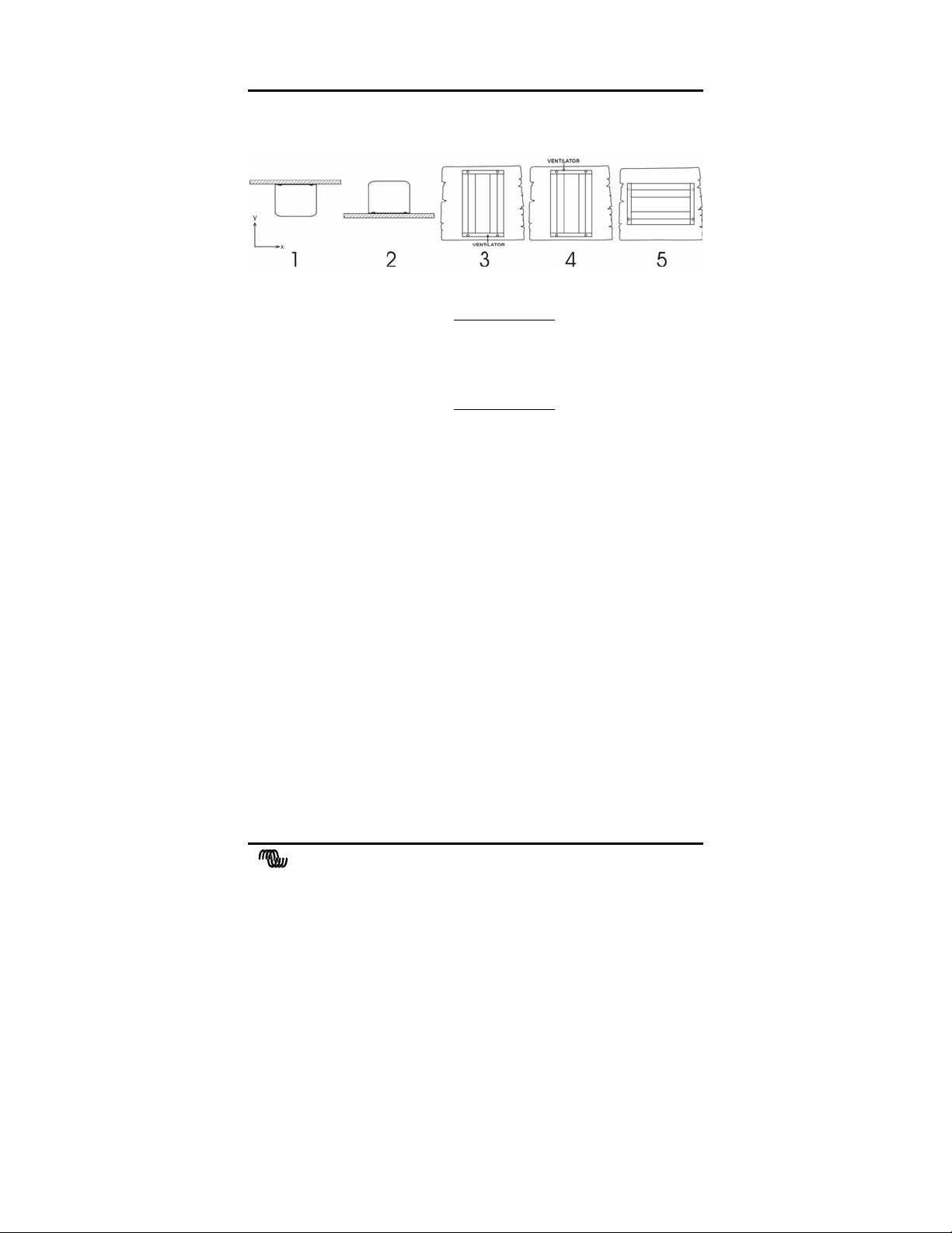
1. INSTALLATION
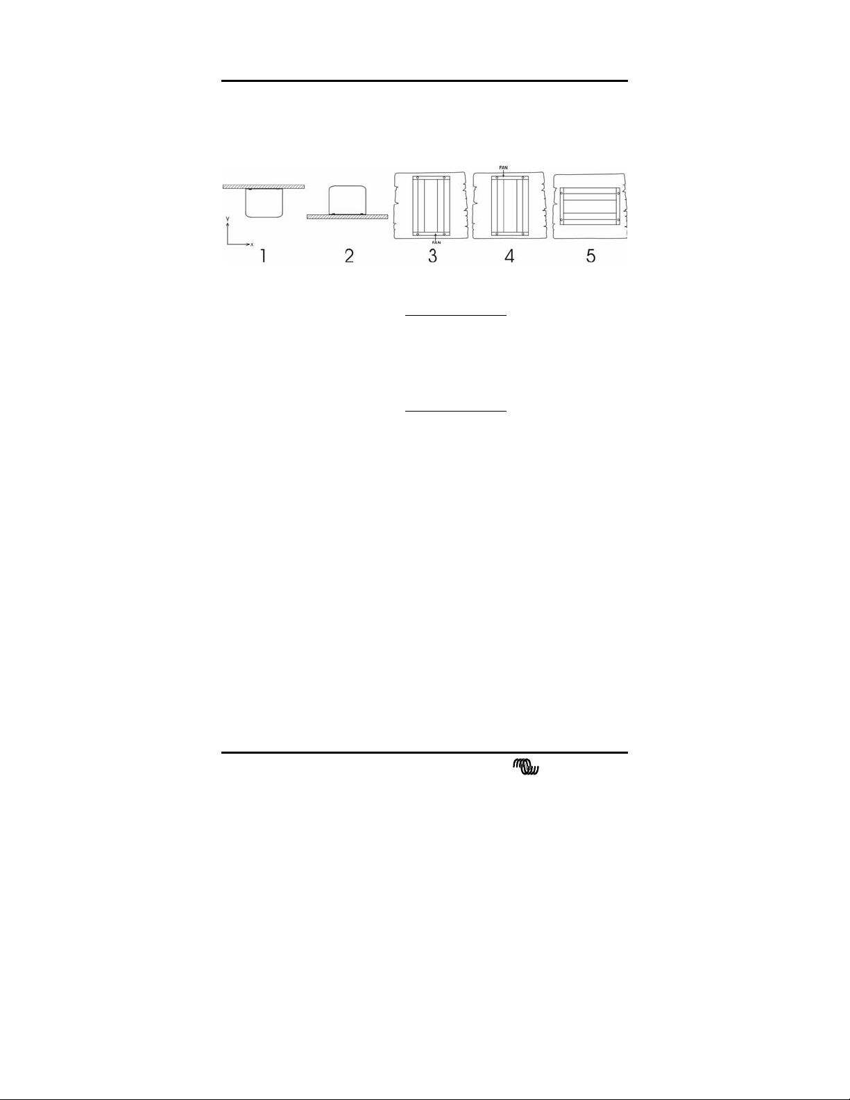
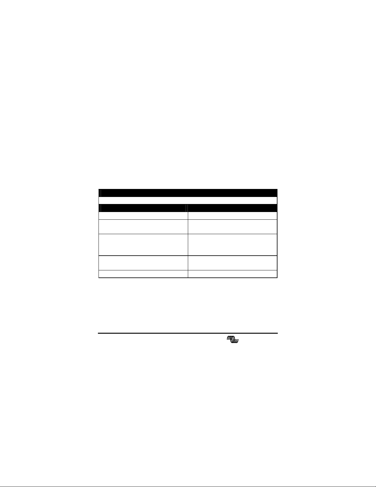
1.1 Location of the inverter
1 Ceiling mounting
(inverted).
2. Base mounting.
3 Vertical wall mounting,
fan at bottom.
4 Vertical wall mounting,
fan on top.
5 Horizontal wall mounting.
For best operating results, the inverter should be placed on a flat
surface. To ensure a trouble free operation of the inverter, it must be
used in locations that meet the following requirements:
a) Avoid any contact with water. Do not expose the inverter to rain or
moisture.
b) Do not place the unit in direct sunlight. Ambient air temperature
should be between 0 °C and 40 °C (humidity < 95% non
condensing). Note that in extreme situations the inverter’s case
temperature can exceed 70 °C.
c) Do not obstruct the airflow around the inverter. Leave at least 10
centimetres clearance around the inverter. When the inverter is
running too hot, it will shut down. When the inverter has reached a
safe temperature level the unit will automatically restart again.
Not recommended
OK
OK (beware of small objects falling
through the ventilation openings on
top).
Not recommended
OK
6 manual
victron ener
Page 7
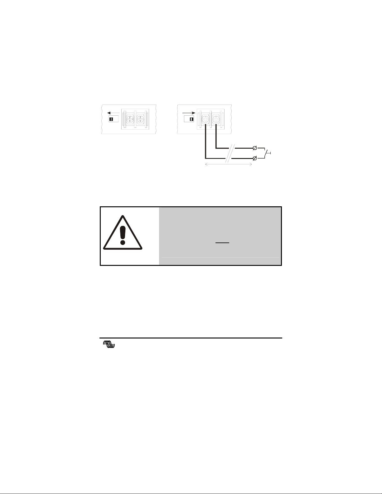
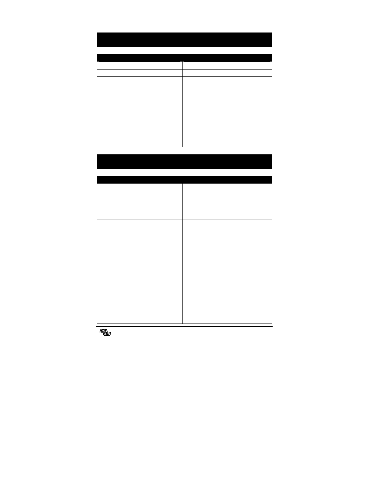
1.2 The “Remote on/off” function (Ph 12/600 and Ph xx/800
h
h
models only)
The Ph 12/600, Ph 24/800 and Ph 48/800 models are equipped with
“Remote on/off” terminals for connection to an external on/off switch.
The two wires of the external switch must be connected to these
terminals as indicated below. When operating the unit by a remote
switch, the slide switch on the frontpanel must be moved to the right
(factory setting is left).
control by l ocal switc
control by remote switc
remote spst
max. 50 meters
The local on/off switch on the frontpanel always overrides the remote
switch. So in order to use the remote switch, the local on/off switch
must be in the ‘on’ or ‘economy’ position.
MAKE SURE THAT WHEN
INSTALLING THE REMOTE SWITCH,
THE BATTERY IS NOT CONNECTED
YET.
CAUTION
switch
victron energy
manual 7
Page 8
gy
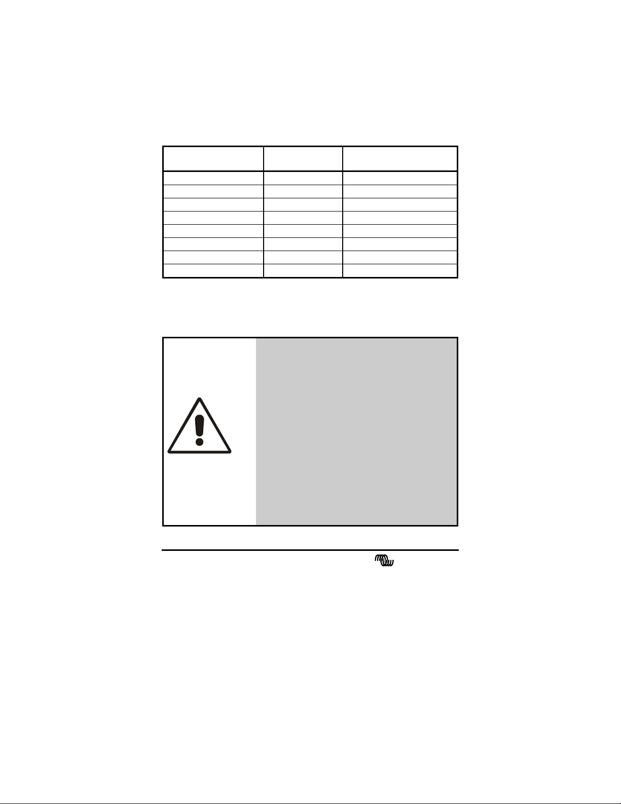
1.3 Battery requirements
For correct operation, the battery voltage should be between
0.92xVnom and 1.23xVnom where Vnom is 12V, 24V or 48V
depending on the model, and must be able to supply sufficient current to
your inverter. The following table displays the recommended battery
capacity per inverter type :
Inverter type : Iin at Pnom : Recommended battery
capacity:
Ph 12/220 18 Adc
Ph 24/220 9 Adc
Ph 48/220 4 Adc
Ph 12/300 26 Adc
Ph 24/350 15 Adc
Ph 12/600 47 Adc
Ph 24/800 29 Adc
Ph 48/800 14 Adc
≥ 50Ah
≥ 30Ah
≥ 20Ah
≥ 100Ah
≥ 60Ah
≥ 200Ah
≥ 120Ah
≥ 60Ah
The inverter shuts down when the battery voltage is below approx.
0.88xVnom or above 1.3xVnom. In a low or high battery situation the
inverter generates one beep per second (except Phxx/220 models).
THE Ph 12/220, Ph 12/300 AND Ph 12/600
MUST BE CONNECTED ONLY TO A 12V
BATTERY. The inverter will not operate from
a 6V battery. The inverter will be damaged
when the battery voltage is higher than 24V.
THE Ph 24/220, Ph 24/350 AND Ph 24/800
MUST BE CONNECTED ONLY TO A 24V
BATTERY. The inverter will not operate from
a 12V battery. The inverter may be damaged
when the battery voltage is higher than 31V.
CAUTION
THE Ph 48/220 AND Ph 48/800 MUST BE
CONNECTED ONLY TO A 48V
BATTERY. The inverter will not operate from
a < 40V battery. The inverter may be damaged
when the battery voltage is higher than 60V.
8 manual
victron ener
Page 9
1.4 Connection to the battery
The Phoenix inverters are equipped with two battery wires with a length
of 1.5 meters. If it is unavoidable to extend these wires, use a wire
gauge of at least 1.5 times larger than the ones supplied with the
inverter. Maximum recommended battery wire length is approx. 3
meters.
1.4.1 General precautions when working with batteries
1. Working in vicinity of a lead acid battery is dangerous. Batteries
can generate explosive gases during operation. Never smoke or
allow a spark or flame in the vicinity of a battery. Provide sufficient
ventilation around the battery.
2. Wear eye and clothing protection. Avoid touching eyes while
working near batteries. Wash your hands when done.
3. If battery acid contacts skin or clothing, wash immediately with
soap and water. If acid enters eye, immediately flood eye with
running cold water for at least 15 minutes and get medical attention
immediately.
4. Be careful when using metal tools in vicinity of batteries. Dropping
a metal tool onto a battery might cause a short-circuit battery and,
possibly an explosion.
5. Remove personal metal items such as rings, bracelets, necklaces,
and watches when working with a battery. A battery can produce a
short-circuit current high enough to melt a ring or the like to metal,
causing severe burns.
THE RED WIRE MUST BE CONNECTED
TO THE POSITIVE (+) TERMINAL AND
THE BLACK WIRE TO THE NEGATIVE
(-) TERMINAL OF THE BATTERY.
Reverse polarity connection of the battery
wires can damage the inverter!
Damage caused by reversed polarity is not
CAUTION
covered by the warranty. Make sure the power
switch is in the OFF ‘0’ position before
connecting the battery.
victron energy
manual 9
Page 10
gy
1.5 Connecting the load
Before you connect your appliance(s) to the inverter, always check it’s
maximum power consumption. Do not connect appliances to the
inverter needing more than the nominal power rating of the inverter
continuously. Some appliances like motors or pumps, draw large inrush
currents in a start-up situation. In such circumstances, it is possible that
the start-up current exceeds the overcurrent trip level of the inverter. In
this case the output voltage will quickly decrease to limit the output
current of the inverter. If the overcurrent trip level is continuously
exceeded, the inverter will shut down and restart within 18 seconds. In
this case it is advisable to disconnect the appliance from the inverter,
since it requires too much power to be driven by this inverter. Note that
at higher ambient temperature levels, the overload capacity of the
inverter is reduced.
WARNING
CAUTION
WHEN CONNECTING MORE THAN
ONE APPLIANCE TO THE INVERTER,
IN COMBINATION WITH A
COMPUTER, NOTE THAT IF ONE OF
THE APPLIANCES DRAWS A HIGH
START CURRENT, IT CAN CAUSE
YOUR COMPUTER TO REBOOT DUE
TO A SUDDEN VOLTAGE DROP.
NEVER CONNECT THE INVERTER’S
OUTPUT TO THE AC DISTRIBUTION
GRID, SUCH AS YOUR HOUSEHOLD AC
WALL OUTLET. IT WILL DAMAGE
THE INVERTER.
10 manual
victron ener
Page 11

1.6 Turning the inverter on
When all the above requirements are checked and satisfied and all
connections are made, it’s time to turn on your Phoenix inverter by
pushing the power switch to the ' I ' position (see top label for push
direction). After a short two tone beep (except Phxx/220 models),
indicating that all internal circuits are checked, the sinewave shaped
output voltage gently rises until 230V/50Hz ± 2% is reached.
When the inverter is not supplying power to an appliance for a longer
time, it’s recommended to use the inverter in the "economy" mode to
heavily reduce the inverter's own power consumption. In this case the
power switch must be pushed in the ' II ' position. In the economy mode
the inverter will generate a testpulse on it's output once per second, to
check that there is a load applied. When the economy mode is activated
(by generating a reversed two tone beep, except Phxx/220 models), the
indicator LED will be continuously on for 4 seconds while the inverter
outputs a continuous 230V (or 115V) sinewave. After this 4 seconds the
continuous output will change to a pulsed output, indicated by a
flashing indicator LED. When a load is connected to the inverter output
(or switched on) drawing more than approx. 12W (or 15W depending
on model), the inverter jumps to the continuous mode immediately,
delivering power to the load. When the load is disconnected again (or
switched off), the indicator LED starts flashing again after 4 seconds,
and the inverter jumps back to the pulsed output economy mode. This
way the inverter automatically jumps to a low power 'sleep' mode when
there is no power demand on the output.
Note that some loads like TV/video equipment (with standby mode) and
alarm clocks need continuous power so that the economy mode can not
be used.
With some small non compensated loads, it is possible that the inverter
jumps from continuous output to pulsed output and vice versa all the
time. In this case you have to connect a small additional load to the AC
output.
victron energy
manual 11
Page 12
gy
WARNING
WARNING
IF THE INVERTER SWITCHES TO AN
‘ERROR MODE’ (SEE CHAPTER 2.1)
DUE TO AN OVERLOAD OR SHORT
CIRCUIT, THE INVERTER WILL
AUTOMATICALLY RESTART AFTER
ABOUT 18 SECONDS.
In case of an over-temperature error, the
inverter will automatically restart after it has
reached an acceptable temperature. Just before
the inverter restarts, it will warn you with a
short beep (except Phxx/220 models).
NEVER TOUCH THE AC
CONNECTIONS WHEN THE INVERTER
IS STILL RUNNING IN AN ERROR
MODE!
THE BUILT IN LARGE ELECTROLYTIC
CAPACITORS CAN HOLD SIGNIFICANT
DC VOLTAGE WHEN THE BATTERIES
ARE DISCONNECTED.
To avoid sparks or short inverter operation, it is
advisable to switch on the inverter for 10
seconds after battery disconnection, before you
transport the inverter.
12 manual
victron ener
Page 13
2. TROUBLESHOOTING
2.1 The flash sequence table
Your Phoenix inverter is equipped with a self-diagnosis system, to
inform you about the cause of inverter shut down. To make this visible
the error/power LED on the front panel of the inverter, can flash in four
different sequences. The duration, or time period, of this sequence is
about 1 second. During this time period the red LED can flash four
times in a row at most. The number of flashes in this time period
indicates the cause of inverter shut down.
In the table below you can find out what kind of flashing sequence
belongs to which error.
victron energy
manual 13
Page 14
gy
2.2 Acoustic messages (except Phxx/220 models)
The inverter is equipped with an acoustic alarm.
There are three kinds of acoustic messages depending on the possible
cause of inverter shutdown. These messages are related to the red LED
flashing sequences mentioned previously.
Message 1: One beep per second. The battery voltage has reached too
low or too high a level.
Message 2: Two beeps per second. The inverter will shut down soon
due to an overloaded output. Note that with very heavy
overloads the alarm will not sound due to fast inverter shut
down.
Message 3: Three beeps per second. The inverter will shut down
when its temperature has risen another three degrees
Celsius.
2.3 Troubleshooting guidelines
PROBLEM : Inverter is not working (red LED OFF)
Possible cause : Remedy :
Power switch in OFF (0) position. Push the power switch to the ON
(I) position.
Poor contact between the
inverter’s battery wires and the
battery terminals.
Blown inverter fuse. The inverter has to be returned for
Very poor battery condition. Replace battery.
Clean battery terminals or inverter
wire contacts. Tighten battery
terminal screws.
service.
14 manual
victron ener
Page 15
PROBLEM : ‘Battery voltage too low or too high’ error keeps on
appearing
Possible cause : Remedy :
Poor battery condition. Replace battery or charge it first.
Poor connection or inadequate
wiring between battery and
inverter, resulting in too much
voltage drop.
When extending the battery wires
of the inverter make sure you use
the correct wire gauge (≥ 1.5 times
larger than the fixed battery wires).
It’s not advisable to extend the
battery wires to more than 3
meters.
General failure in your electrical
system (in case of no direct
battery connection).
Check your electrical system or
consult an electrical engineer to
check it for you.
PROBLEM : ‘Overloaded or shorted output’ error keeps on
appearing
Possible cause : Remedy :
Inverter is overloaded. Make sure that the total power
rating of the connected equipment
is lower than the nominal inverter
power rating.
Connected equipment features a
bad power factor (cosϕ at
sinusoidal currents).
Reduce the required power
consumption of the load. Please
note that, for example, a computer
load features a bad power factor,
which causes a reduction of the
maximum output power of the
inverter by approx. 20%.
Connected equipment causes a
short circuit at the inverter’s
output.
Make sure that the connected
equipment is not broken or
malfunctioning. Check if the AC
power cord between the inverter
and the connected equipment is
OK. Any physical damage on the
power cord can produce a short
circuit. Be careful!.
victron energy
manual 15
Page 16
gy
PROBLEM : ‘Inverter temperature too high. Cooling down’ error
keeps on appearing
Possible cause : Remedy :
Airflow around the inverter is
obstructed.
Make sure there is at least 10
centimetres of clearance around
the inverter. Remove any items
placed on or over the inverter.
Keep the inverter away from direct
sunlight or heat producing
equipment.
Too high ambient temperature. Move the inverter to a cooler place
or provide additional cooling by an
external fan.
Note: Don’t turn-off the inverter when it’s operating in an ‘Inverter
temperature too high. Cooling down’ error. The inverter needs this
error time to cool down.
PROBLEM : Inverter jumps between continuous mode and
economy mode all the time
Possible cause : Remedy :
Connected load is not
compensated or the ratio between
Connect an additional load to the
output.
inrush current and continuous
current is too large.
If none of the above remedies helps to solve the problem you encounter,
contact your local Victron Energy distributor for further help and/or
possible repair of your inverter. Do not open the inverter yourself, there
are dangerous high voltages present inside. Opening the inverter will
directly void your 12 months warranty period.
16 manual
victron ener
Page 17
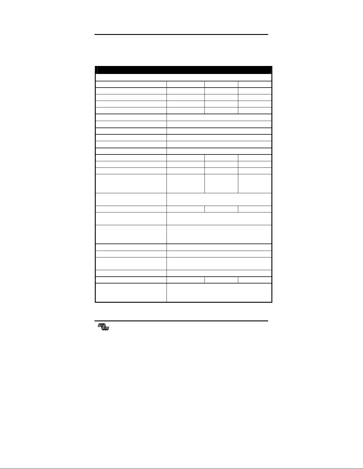
3. TECHNICAL DATA
3.1 Phoenix xx/220
TECHNICAL DATA
Ph 12/220 Ph 24/220 Ph 48/220
Cont. output at 25°C 4) 220VA 220VA 220VA
Cont. output power at 25°C 1) 175W 175W 175W
Cont. output power at 40°C 1) 150W 150W 150W
Peak power 350W 400W 400W
Output voltage
Output frequency
Output waveform True sinewave
Total harmonic distortion Maximum 5% 3)
Admissible cos ϕ of load
Input voltage (±3% tol.):
Nominal 12Vdc 24Vdc 48Vdc
Range 10.52) – 16Vdc 212) – 31Vdc 412) – 60Vdc
Maximum efficiency 90% 91% 93%
No load power consumption at
nominal input voltage
[economy]
Operating temperature range
(ambient)
Economy threshold Pout = 12W Pout = 15W Pout = 15W
Protections against Short circuit, overload, high temperature and
Indications (by preprogrammed flashing
sequences of the power LED)
DC input connection
AC output connection IEC-320 AC outlet
Enclosure body size
(l x h x w)
Protection class IP20
Total weight 2.3 kg 2.3 kg 2.4 kg
The inverter complies with the
following standards :
230Vac ± 2% or 115Vac ± 2%
50Hz ± 0.05% or 60Hz ± 0.05%
0.6 – 1
< 2.8W
[0.6W]
Power on, short circuit/overload, high
temperature, high/low battery voltage and
Two wires, length 1.5 meters, ∅ 4mm²
154 x 98 x 130 (without mounting brackets)
EN50081-1 Generic Emissions Standard
EN50082-1 Generic Immunity Standard
EN60335-2 Safety Standard
< 3W
[0.8W]
-20 °C to +50 °C
low battery voltage
economy mode
< 4W
[1.2W]
victron energy
manual 17
Page 18
gy
3.2 Phoenix 12/300 and Phoenix 24/350
TECHNICAL DATA
Phoenix 12/300 Phoenix 24/350
Cont. output at 25°C 4) 300VA 350VA
Cont. output power at 25°C 1) 250W 300W
Cont. output power at 40°C 1) 230W 275W
Peak power 700W 800W
Output voltage
Output frequency
Output waveform True sinewave
Total harmonic distortion Maximum 5% 3)
Admissible cos ϕ of load
Input voltage (±3% tol.):
Nominal 12Vdc 24Vdc
Range 10.52) – 16Vdc 212) – 31Vdc
Maximum efficiency 91% 93%
No load power consumption at
nominal input voltage
[economy]
Operating temperature range
(ambient)
Economy threshold Pout = 12W Pout = 15W
Protections against Short circuit, overload, high temperature and
Indications (by preprogrammed flashing
sequences of the power LED)
DC input connection
AC output connection IEC-320 AC outlet
Enclosure body size
(l x h x w)
Protection class IP20
Total weight 3.5 kg 3.5 kg
The inverter complies with the
following standards :
230Vac ± 2% or 115Vac ± 2%
50Hz ± 0.05% or 60Hz ± 0.05%
0.6 – 1
< 3W
[0.7W]
-20 °C to +50 °C
low battery voltage
Power on, short circuit/overload, high
temperature, high/low battery voltage and
economy mode
Two wires, length 1.5 meters, ∅ 4mm²
184 x 98 x 130 (without mounting brackets)
EN50081-1 Generic Emissions Standard
EN50082-1 Generic Immunity Standard
EN60335-2 Safety Standard
< 3.5W
[0.8W]
Note : the given specifications are subject to change without notice
18 manual
victron ener
Page 19
3.3 Phoenix 12/600, 24/800 and 48/800
TECHNICAL DATA
Ph 12/600 Ph 24/800 Ph 48/800
Cont. output at 25°C 4) 600VA 800VA 800VA
Cont. output power at 25°C 1) 480W 600W 600W
Cont. output power at 40°C 1) 430W 540W 540W
Peak power 1000W 1200W 1250W
Output voltage
Output frequency
Output waveform True sinewave
Total harmonic distortion Maximum 5% 3)
Admissible cos ϕ of load
Input voltage (±3% tol.):
Nominal 12Vdc 24Vdc 48Vdc
Range 10.52) – 16Vdc 212) – 31Vdc 412) – 60Vdc
Maximum efficiency 92% 94% 94%
No load power consumption at
nominal input voltage
[economy]
Operating temperature range
(ambient)
Economy threshold Pout = 15W Pout = 15W Pout = 15W
Protections against Short circuit, overload, high temperature and
Indications (by preprogrammed flashing
sequences of the power LED)
DC input connection
AC output connection IEC-320 AC outlet
Enclosure body size
(l x h x w)
Protection class IP20
Total weight 6.2 kg 6.2 kg 6.2 kg
The inverter complies with the
following standards :
1)
Measured with resistive load. Power ratings are subject to a
tolerance of ± 4%.
2)
Undervoltage limit is dynamic. This limit decreases with increasing
230Vac ± 2% or 115Vac ± 2%
50Hz ± 0.05% or 60Hz ± 0.05%
0.2 – 1
< 4.8W
[0.4W]
high/low battery voltage
Power on, short circuit/overload, high
temperature, high/low battery voltage and
Two wires, length 1.5 meters, ∅ 10mm²
228 x 113 x 163 (without mounting brackets)
EN50081-1 Generic Emissions Standard
EN50082-1 Generic Immunity Standard
EN60335-2 Safety Standard
< 6.5W
[0.7W]
-20 °C to +50 °C
economy mode
< 8.2W
[0.5W]
load to compensate the voltage drop across cables and connections.
victron energy
manual 19
Page 20

gy
3)
Measured with nominal load at Ta=25ºC and at nominal input and
outputvoltage.
4)
Non linear load, crest factor 3:1
3.4 Enclosure dimensions Ph xx/220, Ph 12/300 and Ph
24/350
See page 79.
3.5 Enclosure dimensions Ph 12/600, Ph 24/800 and Ph
48/800
See page 80.
20 manual
victron ener
Page 21

4. BATTERY CAPACITY
4.1 Calculation of the minimum required battery capacity
If the power ratings of the equipment to be powered by the Phoenix
inverter and the duration that the inverter is expected to power the
equipment are known, the minimum battery capacity can be calculated.
Make a list of all equipment to be powered by the Phoenix inverter and
sum up each single power consumption multiplied by the duration of time
in hours, during which power will be consumed (Watt-hours). Add the
internal loss of the Phoenix inverter.
The calculation on the internal loss is a two step process. First we
calculate the loss when the inverter is supplying power to a load. The
efficiency of the inverter in this state is 85%, adding roughly 15% to the
power consumption. When the inverter is not supplying power to a load,
power consumption is approximately 4W.
Determine the number of Ah by dividing the power consumption by the
nominal battery voltage (for example 24 V
battery capacity-consumption in Ah's. Multiply this value with a safety
factor of 1,7 and the result is the recommended minimum battery
capacity.
). The result is the total
DC
victron energy
manual 21
Page 22
victron energy
GEBRUIKSAANWIJZING
Phoenix 12/220
Phoenix 24/220
Phoenix 48/220
Phoenix 12/300
Phoenix 24/350
Phoenix 12/600
Phoenix 24/800
Phoenix 48/800
22 Gebruiksaanwijzing
victron energy
Page 23

gy
INLEIDING
Victron Energy heeft op het gebied van het ontwikkelen en produceren
van elektrische energievoorzieningsystemen internationale bekendheid
verworven.
Victron Energy heeft deze wereldfaam met name te danken aan de
voortdurende inspanningen van de ontwikkelingsafdeling. Deze afdeling
houdt zich bezig met onderzoek naar en realisatie van mogelijkheden om
nieuwe technologieën die zinvolle technische en economische bijdragen
leveren, in de producten van Victron Energy te implementeren.
Deze beproefde filosofie heeft geleid tot de ontwikkeling van een
complete serie energieverzorgende apparatuur waarin de laatste
technische ontwikkelingen zijn verwerkt. De apparatuur van Victron
Energy voldoet aan de strengste eisen.
Victron Energy levert kwalitatief hoogwaardige wisselstroomvoorzieningen voor gebruik op plaatsen waar geen permanente aansluiting op
het elektriciteitsnet (230 of 115 Vac) voorhanden is.
Met behulp van de apparatuur van Victron Energy kan een automatisch
‘stand alone’ energievoorzieningsysteem worden gecreëerd. Maak voor
de configuratie naast krachtige accu’s gebruik van een omvormer en een
acculader.
De apparatuur van Victron Energy is geschikt voor alle soorten
elektrische apparaten voor huishoudelijk, technisch, en industrieel
gebruik, inclusief storingsgevoelige instrumenten. De Victron Energy
systemen zijn hoogwaardige energiebronnen die borg staan voor een
storingsvrije werking.
Deze gebruiksaanwijzing beschrijft de installatie, de werking en de
praktische toepassing van de Ph 12/220, Ph 24/220, Ph 48/220, Ph
12/300, Ph 24/350, Ph 12/600, Ph 24/800 en de Ph 48/800
sinusomvormers. Bovendien wordt in deze gebruiksaanwijzing ingegaan
op de beveiligingsvoorzieningen en de technische specificaties van de
Phoenix omvormer.
N.B. : in deze gebruiksaanwijzing wordt in sommige gevallen gebruik
gemaakt van de afkorting ‘Ph’ in plaats van Phoenix .
victron ener
Gebruiksaanwijzing 23
Page 24

INHOUD
INLEIDING........................................................................ 23
1. INSTALLATIE............................................................... 25
1.1 Plaatsing van de omvormer 25
1.2 De “Remote on/off” functie (alleen voor Ph 12/600 en Ph
1.3 Accu eisen 27
1.4 Het aansluiten van de accu 28
1.4.1 Voorzorgsmaatregelen omtrent het werken met accu's 28
1.5 Aansluiting van de belasting 29
1.6 Activeren van de omvormer 30
2. HET OPLOSSEN VAN STORINGEN.......................... 32
2.1 Optische alarmen 32
2.2 Akoestische alarmen (behalve bij Ph xx/220 modellen) 33
2.3 Storingen met mogelijke oplossingen 33
3. TECHNISCHE GEGEVENS......................................... 36
3.1 Phoenix xx/220 36
3.2 Phoenix 12/300 en Phoenix 24/350 37
3.3 Phoenix 12/600, 24/800 en 48/800 38
3.4 Afmetingen behuizing Ph xx/220, Ph 12/300 en Ph 24/350 39
3.5 Afmetingen behuizing Ph 12/600, Ph 24/800 en Ph 48/800 39
xx/800 modellen) 26
4. ACCUCAPACITEIT ...................................................... 40
4.1 Het bereken van de minimaal benodigde accucapaciteit 40
24 Gebruiksaanwijzing
victron energy
Page 25
gy
1. INSTALLATIE
1.1 Plaatsing van de omvormer
1 Plafond montage Niet aanbevolen
2 Vloer montage OK
3 Verticale muur montage,
ventilator onder
OK (pas op kleine objecten die door
de ventilatie openingen aan de
bovenkant kunnen vallen)
4 Verticale muur montage,
Niet aanbevolen
ventilator boven
5 Horizontale muur
OK
montage
Om een probleemloze werking van de omvormer te kunnen garanderen,
moet de locatie waarin deze wordt geïnstalleerd aan de volgende eisen
voldoen:
a) Vermijdt elk contact met water. Stel de omvormer niet bloot aan
regen of mist.
b) Plaats de omvormer niet in direct zonlicht.
De omgevingstemperatuur moet tussen 0 °C en 40 °C liggen
(luchtvochtigheid < 95% niet condenserend). In extreme situaties
kan de behuizing van de omvormer een temperatuur bereiken van
meer dan 70 °C.
c) Vermijd obstructie van de luchtstroming rond de omvormer. Laat
minstens 10 centimeter ruimte vrij rond de omvormer. Wanneer de
omvormer een te hoge temperatuur heeft bereikt, zal deze zichzelf
uitschakelen. Als de omvormer is afgekoeld tot een acceptabele
temperatuur schakelt deze weer in.
victron ener
Gebruiksaanwijzing 25
Page 26

1.2 De “Remote on/off” functie (alleen voor Ph 12/600
en Ph xx/800 modellen)
De Phoenix 12/600, 24/800 en 48/800 modellen bieden de mogelijkheid
een externe aan/uit schakelaar aan te sluiten. De twee draden van deze
schakelaar moeten aangesloten worden op de klemmen zoals hieronder
is aangegeven. Wanneer de omvormer bedient gaat worden door een
externe aan/uit schakelaar, moet de schuif schakelaar op het frontpaneel
naar rechts geschoven worden (af fabriek positie is links).
bediening do or lokale
schakelaar
De lokale aan/uit schakelaar op het frontpaneel zal altijd de omvormer
kunnen uitschakelen, ongeacht de stand van de externe schakelaar. De
lokale schakelaar moet altijd in de stand ‘power on’ of ‘economy’ staan
om de externe schakelaar te kunnen gebruiken.
BIJ HET INSTALLEREN VAN DE EXTERNE
AAN/UIT SCHAKELAAR MAG DE
OMVORMER NIET ZIJN AANGESLOTEN OP
DE ACCU.
bedi eni ng d oo r externe
schakelaar
schakelaar
max. 50 meter
externe
26 Gebruiksaanwijzing
victron energy
Page 27

gy
1.3 Accu eisen
Voor een correcte werking moet de accuspanning tussen 0,92xVnom en
1,23xVnom liggen, Vnom is afhankelijk van het model 12V, 24V of
48V. De accu moet in staat zijn om voldoende stroom te kunnen leveren
aan de omvormer. De volgende tabel geeft de geadviseerde accu
capaciteit weer:
Omvormer model: Iin bij Pnom : Geadviseerde accu
capaciteit:
Ph 12/220 18 Adc
Ph 24/220 9 Adc
Ph 48/220 4 Adc
Ph 12/300 26 Adc
Ph 24/350 15 Adc
Ph 12/600 47 Adc
Ph 24/800 29 Adc
Ph 48/800 14 Adc
≥ 50Ah
≥ 30Ah
≥ 20Ah
≥ 100 Ah
≥ 60 Ah
≥ 200 Ah
≥ 120 Ah
≥ 60 Ah
De omvormer schakelt uit wanneer de accuspanning onder ca.
0,88xVnom of boven ca. 1,3xVnom ligt. Bij een te lage/hoge
accuspanning genereert de omvormer één akoestisch signaal per
seconde (behalve Ph xx/220 modellen).
DE Ph 12/220, Ph 12/300 EN Ph 12/600 MOGEN
ALLEEN OP EEN 12V ACCU AANGESLOTEN
WORDEN. De omvormer werkt niet op een 6V accu.
De omvormer zal beschadigen als de accu spanning
hoger wordt dan 24V.
DE Ph 24/220, Ph 24/350 EN Ph 24/800 MOGEN
ALLEEN OP EEN 24V ACCU AANGESLOTEN
WORDEN. De omvormer werkt niet op een 12V
accu. De omvormer kan beschadigen als de
accuspanning hoger wordt dan 31V.
DE Ph 48/220 EN Ph 48/800 MOGEN ALLEEN
OP EEN 48V ACCU AANGESLOTEN WORDEN.
De omvormer werkt niet op een < 40V accu. De
omvormer kan beschadigen als de accuspanning hoger
wordt dan 60V.
victron ener
Gebruiksaanwijzing 27
Page 28

1.4 Het aansluiten van de accu
De Phoenix omvormers zijn uitgerust met twee accukabels met een
lengte van 1,5 meter. Als verlenging van de accukabels onvermijdelijk
is, moet een draad diameter worden gebruikt van minstens 1,5 keer de
diameter van de vaste omvormer kabels. De maximum aanbevolen
accukabel lengte is circa 3 meter.
1.4.1 Voorzorgsmaatregelen omtrent het werken met accu's
1. Werken in de nabijheid van accu's kan gevaarlijk zijn. Accu's
kunnen explosieve gassen produceren. Vermijd roken, vonken of
open vuur in de buurt van accu's. Zorg voor voldoende ventilatie.
2. Draag oog en kleding bescherming. Vermijd het aanraken van de
ogen wanneer er met accu's gewerkt wordt. Was de handen na het
werken met accu's.
3. Als accuzuur in contact komt met de huid of kleding, was dit dan
onmiddellijk af met water en zeep. Als het zuur in contact komt
met de ogen, spoel dan onmiddellijk met koud stromend water. Doe
dit gedurende 15 minuten en roep zo nodig medische hulp in.
4. Wees voorzichtig met het gebruik van metalen gereedschap in de
buurt van accu's. Het laten vallen van metalen objecten op de accu
kan kortsluiting en explosie gevaar opleveren.
5. Verwijder persoonlijke zaken zoals ringen, armbanden, horloges en
kettingen wanneer met accu's gewerkt wordt. Accu's kunnen
kortsluitstromen veroorzaken die metalen objecten volledig kunnen
laten smelten met ernstige brandwonden tot gevolg.
28 Gebruiksaanwijzing
victron energy
Page 29

gy
DE RODE DRAAD MOET AANGESLOTEN
WORDEN OP DE POSITIEVE (+)
ACCUKLEM EN DE ZWARTE DRAAD OP
DE NEGATIEVE (-) ACCUKLEM.
Verkeerd om aansluiten van de accukabels kan de
omvormer beschadigen!
Schade ontstaan door het verkeerd om aansluiten
van de accukabels valt niet binnen de garantie.
Zorg ervoor dat de aan/uit schakelaar in de ‘0’
positie staat voordat u de accu aansluitingen
maakt.
1.5 Aansluiting van de belasting
Controleer voordat u uw apparatuur op de omvormer uitgang aansluit,
of het totale stroomverbruik van de betreffende apparaten niet hoger is
dan de nominale uitgangsstroom van de omvormer. Sommige apparaten
zoals elektrisch gereedschap en pompen hebben een hoge
inschakelstroom bij het opstarten. In dit geval is het mogelijk dat zo'n
inschakelstroom de interne stroombeveiliging van de omvormer
aanspreekt waardoor de uitgangsspanning van omvormer kortstondig
daalt. Als deze stroom beveiliging in een korte tijd een aantal keren
achter elkaar wordt aangesproken, zal de omvormer in de
overbelastingsbeveiliging springen zodat de uitgangsspanning
verdwijnt. In dit geval is het raadzaam om de aangesloten belasting te
verminderen omdat deze te zwaar is voor de omvormer.
Na ca. 18 seconden start de omvormer automatisch weer op. Bij hogere
omgevingstemperaturen daalt de overbelastingscapaciteit van de
omvormer.
victron ener
Gebruiksaanwijzing 29
Page 30

1.6 Activeren van de omvormer
Wanneer aan alle eerder genoemde eisen is voldaan en alle
aansluitingen zijn gemaakt, kan uw Phoenix omvormer worden
ingeschakeld door de aan/uit schakelaar in de ' I ' positie (zie sticker
voor aanwijzingen) te zetten. Na een kort tweetonig audiosignaal
(behalve bij Ph xx/220 modellen), wordt de sinusvormige
uitgangsspanning opgebouwd totdat 230V/50Hz ± 2% bereikt is.
Wanneer de omvormer voor een langere tijd geen vermogen hoeft de
leveren aan een belasting, wordt het aanbevolen om de omvormer in de
"economy" modus te zetten. Op deze manier wordt het eigenverbruik
van de omvormer drastisch gereduceerd. Om de economy modus in te
schakelen, dient u de aan/uit schakelaar in de ' II ' stand te zetten. In de
economy modus genereert de omvormer elke seconde een testpuls op de
uitgang, om te controleren of er een belasting is aangesloten. Wanneer
de economy modus wordt geactiveerd (bevestiging middels omgekeerd
tweetonig audio signaal, behalve bij Ph xx/220 modellen), zal de
indicatie LED 4 seconden lang continu branden. Hierbij is er continu
230VAC (of 115Vac) aanwezig op de uitgang. Na deze 4 seconden zal
de continue uitgangsspanning overgaan in een pulserende
uitgangsspanning, waarbij de indicatie LED knippert. Als nu de
WANNEER ER MEER DAN ÉÉN APPARAAT
WAARONDER EEN COMPUTER WORDT
AANGESLOTEN OP DE OMVORMER, KAN
HET VOORKOMEN DAT WANNEER ÉÉN
VAN DE APPARATEN OPSTART, DE
COMPUTER GERESET WORDT VANWEGE
EEN PLOTSELINGE SPANNINGSVAL.
SLUIT DE UITGANG VAN DE OMVORMER
NOOIT AAN OP HET VASTE
ELEKTRICITEITSNET VIA BIJV. EEN
WANDCONTACTDOOS. HIERDOOR KAN DE
OMVORMER ZWAAR BESCHADIGEN.
30 Gebruiksaanwijzing
victron energy
Page 31

gy
belasting op de uitgang van de omvormer wordt ingeschakeld, waarbij
het opgenomen vermogen 12W (of 15W, afhankelijk van model) of
meer bedraagt, geeft de omvormer direct een continue uitgangsspanning
af. En wanneer de belasting weer afgekoppeld of uitgeschakeld wordt,
gaat de indicator LED na 4 seconden wederom knipperen. De
omvormer is nu weer overgeschakeld naar een energie besparende
pulserende uitgangsspanning.
Sommige belastingen zoals TV/video apparatuur (met standby mode) en
wekkers, kunnen alleen goed functioneren met een continue
voedingsspanning waardoor de ASB modus niet kan worden gebruikt.
Met sommige kleine ongecompenseerde belastingen is het mogelijk dat
de omvormer steeds tussen een continue en een pulserende uitgang blijft
springen. In dit geval is het raadzaam om een extra belasting aan te
sluiten op de AC uitgang.
WANNEER DE OMVORMER IN EEN
‘ERROR MODE’ SPRINGT (ZIE
HOOFDSTUK 2.1) VANWEGE
OVERBELASTING OF KORTSLUITING,
ZAL DE OMVORMER WEER
AUTOMATISCH OPSTARTEN NA CIRCA 18
SEC.
In het geval van een temperatuur error, zal de
omvormer pas weer automatisch opstarten nadat er
een acceptabele omvormer temperatuur is bereikt.
Vlak voordat de omvormer weer opstart, wordt dit
kenbaar gemaakt door een kort akoestisch signaal
(behalve bij Ph xx/220 modellen).
VERRICHT NOOIT WERKZAAMHEDEN AAN
DE AC AANSLUITINGEN WANNEER DE
OMVORMER IN EEN ‘ERRORMODE’
WERKT!
DE GROTE INTERNE CONDENSATOR KAN
OP SPANNING BLIJVEN STAAN WANNEER
DE ACCU’S ZIJN AFGEKOPPELD.
Om vonken of korte omvormer werking te
voorkomen, is het raadzaam om de omvormer
circa 10 seconden aan te zetten nadat deze is
losgekoppeld van de accu’s. Hierna kunt u de
omvormer veilig transporteren.
victron ener
Gebruiksaanwijzing 31
Page 32

2. HET OPLOSSEN VAN STORINGEN
2.1 Optische alarmen
Uw Phoenix omvormer is uitgerust met een zelf diagnose systeem om u
te kunnen informeren over de oorzaak van een automatische omvormer
uitschakeling. Om dit te visualiseren kan de rode indicatie LED, in
bepaalde patronen gaan knipperen. De tijdsduur van zo'n knipper
patroon is circa 1 seconde. Gedurende deze tijd kan de rode LED
maximaal 4 licht signalen geven.
In de volgende tabel kunt u zien welk error/alarm type er bij welk
knipper patroon hoort.
32 Gebruiksaanwijzing
victron energy
Page 33

gy
2.2 Akoestische alarmen (behalve bij Ph xx/220 modellen)
De omvormer is uitgerust met een akoestisch alarm.
Er zijn drie verschillende akoestische alarmen ingebouwd. Deze zijn
qua patroon gerelateerd aan eerder genoemde optische alarmen:
Alarm 1: Eén signaal per seconde. De accuspanning heeft een te lage
of te hoge spanningsbereik gehaald. Als de accuspanning
respectievelijk iets verder daalt of stijgt, zal de omvormer in
de accuspanningserror springen om accu beschadiging tegen
te gaan.
Alarm 2: Twee signalen per seconde. De omvormer zal uitschakelen
vanwege een overbelaste uitgang. Bij zeer zware
overbelastingen zal dit alarm niet geactiveerd worden omdat
de omvormer dan snel in de errormode zal springen.
Alarm 3: Drie signalen per seconde. De omvormer zal uitschakelen
wanneer de temperatuur nog verder toeneemt met 3 graden
Celsius.
2.3 Storingen met mogelijke oplossingen
PROBLEEM : Omvormer werkt niet (Rode LED is uit)
Mogelijke oorzaak : Remedie :
Aan/uit schakelaar staat in de UIT (0)
positie.
Slecht contact tussen de omvormer
accukabels en de accupolen.
Zekering defect. De omvomer moet geretourneerd worden
Zeer slechte accu conditie. Herlaad of vervang de accu.
Druk deze schakelaar in de AAN (I)
positie.
Maak de accupolen en/of draadcontacten
schoon. Draai de bevestigingsschroeven
goed aan.
voor service.
victron ener
Gebruiksaanwijzing 33
Page 34

PROBLEEM : ‘Accuspanning te laag of te hoog’ alarm blijft optreden
Mogelijke oorzaak : Remedie :
Slechte accu conditie. Herlaad of vervang de accu.
Slechte verbinding of verkeerde
bedrading tussen omvormer en accu,
resulterend in een te hoog
spanningsverlies.
Een fout in uw elektrische systeem (in
het geval van een niet directe
verbinding met de accu).
Ga alle verbindingen na. Als de
accukabels verlengd zijn moet de juiste
draaddikte worden gebruikt (≥ 1.5 keer
de bijgeleverde draad oppervlakte). Het
wordt niet aanbevolen de accukabels tot
meer dan circa 3 meter te verlengen.
Controleer uw elektrische systeem of
raadpleeg hiervoor een elektrotechnicus.
PROBLEEM : ‘Uitgang overbelast of kortgesloten’ alarm blijft optreden
Mogelijke oorzaak : Remedie :
Omvormer is overbelast. Controleer of het totale vermogen van de
aangesloten belasting niet het nominale
vermogen van de omvormer overschrijdt.
Aangesloten belasting heeft een
slechte power factor (cosϕ bij
sinusvormige stromen).
Aangesloten belasting veroorzaakt
een kortsluiting aan de uitgang van
de omvormer.
Reduceer de grootte van de belasting. N.B.
een computer bijvoorbeeld, heeft een
slechte power factor waardoor het
maximale werkelijke uitgangssvermogen
van de omvormer met ca. 20% daalt.
Controleer of de aangesloten belasting niet
defect is inclusief het netsnoer tussen de
belasting en de omvormer. Een fysiek
beschadigd netsnoer kan een kortsluiting
veroorzaken. Wees voorzichtig in dit soort
omstandigheden!
34 Gebruiksaanwijzing
victron energy
Page 35

gy
PROBLEEM : ‘Omvormer temperatuur te hoog’ alarm blijft optreden
Mogelijke oorzaak : Remedie :
Luchtstroom rond de omvormer is
geblokkeerd.
Te hoge omgevingstemperatuur. Verplaats de omvormer naar een koelere
Zorg voor minstens 10 centimeter ruimte
om de omvormer. Verwijder eventuele
voorwerpen die op of over de omvormer
liggen. Houd de omvormer uit direct
zonlicht of warmte producerende
apparatuur.
plaats of zorg voor extra koeling met een
extra externe ventilator.
N.B.: Zet de omvormer niet uit wanneer deze werkt in een 'Omvormer
temperatuur te hoog' alarm. De omvormer heeft deze tijd nodig om af te
koelen en laat daarom ook de interne ventilator draaien.
PROBLEEM : Omvormer springt steeds tussen continu en economy mode
Mogelijke oorzaak : Remedie :
Aangesloten belasting is niet
gecompenseerd of de verhouding
tussen inschakelstroom en continu
stroom is te groot.
Sluit een kleine extra belasting aan.
Als géén van de bovengenoemde remedies een oplossing bieden bij de
problemen die u ondervindt, is het raadzaam om contact op te nemen
met uw locale Victron Energy dealer voor verdere hulp en/of eventuele
reparatie. Open zelf nooit de omvormer, er kunnen gevaarlijk hoge
spanningen aanwezig zijn in de omvormer! Tevens zal in dat geval de
12 maanden garantie periode komen te vervallen.
victron ener
Gebruiksaanwijzing 35
Page 36

3. TECHNISCHE GEGEVENS
3.1 Phoenix xx/220
TECHNICAL DATA
Ph 12/220 Ph 24/220 Ph 48/220
Verm. P cont. bij 25°C 4) 220VA 220VA 220VA
Verm. P cont. bij 25°C 1) 175W 175W 175W
Verm. P cont. bij 40°C 1) 150W 150W 150W
Piekvermogen 350W 400W 400W
Uitgangsspanning
Uitgangsfrequentie
Spanningsvorm Zuiver sinus
Totale harmonische
vervorming (THD)
Toegestane cos ϕ van de
belasting
Ingangsspanning (± 3% tol.):
Nominaal 12Vdc 24Vdc 48Vdc
Bereik 10.52) – 16Vdc 212) – 31Vdc 412) – 60Vdc
Maximaal rendement 90% 91% 93%
Nullast vermogens consumptie
bij nominale ingangsspanning
[economy]
Aanbevolen
omgevingstemperatuur
Economy vanaf Pout = 12W Pout = 15W Pout = 15W
Beveiligd tegen Kortsluiting, overbelasting, te hoge
Indicaties (d.m.v. knipper
patronen voor de indicatie
LED)
Aansluiting DC ingang
Aansluiting AC uitgang IEC-320 Euro chassisdeel female
Afmetingen (l x h x b) 154 x 98 x 130 (excl. bevestigingslippen)
Beschermingsklasse IP20
Gewicht 2.3 kg 2.3 kg 2.4 kg
De omvormer voldoet aan de
volgende normen:
230Vac ± 2% of 115Vac ± 2%
50Hz ± 0.05% of 60Hz ± 0.05%
Maximaal 5% 3)
0.6 – 1
< 2.8W
[0.6W]
temperatuur en te lage accuspanning
Omvormer in bedrijf,
kortsluiting/overbelasting, te hoge temperatuur
te hoge of lage accuspanning en Economy
Twee draden, lengte 1.5 meter, ∅ 4mm²
EN50081-1 Generic Emissions Standard
EN50082-1 Generic Immunity Standard
EN60335-2 Safety Standard
< 3W
[0.8W]
-20 °C tot +50 °C
< 4W
[1.2W]
36 Gebruiksaanwijzing
victron energy
Page 37

gy
3.2 Phoenix 12/300 en Phoenix 24/350
TECHNISCHE GEGEVENS
Phoenix 12/300 Phoenix 24/350
Verm. P cont. bij 25°C 4) 300VA 350VA
Verm. P cont. bij 25°C 1) 250W 300W
Verm. P cont. bij 40°C 1) 230W 275W
Piekvermogen 700W 800W
Uitgangsspanning
Uitgangsfrequentie
Spanningsvorm Zuiver sinus
Totale harmonische
vervorming (THD)
Toegestane cos ϕ van de
belasting
Ingangsspanning (± 3% tol.):
Nominaal 12Vdc 24Vdc
Bereik 10.52) – 16Vdc 212) – 31Vdc
Maximaal rendement 91% 93%
Nullast vermogens consumptie
bij nominale ingangsspanning
[economy]
Aanbevolen
omgevingstemperatuur
Economy vanaf Pout = 12W Pout = 15W
Beveiligd tegen Kortsluiting, overbelasting, te hoge
Indicaties (d.m.v. knipper
patronen voor de indicatie
LED)
Aansluiting DC ingang
Aansluiting AC uitgang IEC-320 Euro chassisdeel female
Afmetingen (l x h x b) 184 x 98 x 130 (excl. bevestigingslippen)
Beschermingsklasse IP20
Gewicht 3.5 kg 3.5 kg
De omvormer voldoet aan de
volgende normen:
N.B.: voorgaande gegevens kunnen zonder aankondiging van de fabrikant
veranderen.
230Vac ± 2% of 115Vac ± 2%
50Hz ± 0.05% of 60Hz ± 0.05%
Maximaal 5% 3)
0.6 – 1
< 3W
[0.7W]
-20 °C tot +50 °C
temperatuur en te lage accuspanning
Omvormer in bedrijf,
kortsluiting/overbelasting, te hoge temperatuur
te hoge of lage accuspanning en Economy
Twee draden, lengte 1.5 meter, ∅ 4mm²
EN50081-1 Generic Emissions Standard
EN50082-1 Generic Immunity Standard
EN60335-2 Safety Standard
< 3.5W
[0.8W]
victron ener
Gebruiksaanwijzing 37
Page 38

3.3 Phoenix 12/600, 24/800 en 48/800
TECHNICAL DATA
Ph 12/600 Ph 24/800 Ph 48/800
Verm. P cont. bij 25°C 4) 600VA 800VA 800VA
Verm. P cont. bij 25°C 1) 480W 600W 600W
Verm. P cont. bij 40°C 1) 430W 540W 540W
Piekvermogen 1000W 1200W 1250W
Uitgangsspanning
Uitgangsfrequentie
Spanningsvorm Zuiver sinus
Totale harmonische
vervorming (THD)
Toegestane cos ϕ van de
belasting
Ingangsspanning (± 3% tol.):
Nominaal 12Vdc 24Vdc 48Vdc
Bereik 10.52) – 16Vdc 212) – 31Vdc 412) – 60Vdc
Maximaal rendement 92% 94% 94%
Nullast vermogens consumptie
bij nominale ingangsspanning
[economy]
Aanbevolen
omgevingstemperatuur
Economy vanaf Pout = 15W Pout = 15W Pout = 15W
Beveiligd tegen Kortsluiting, overbelasting, te hoge
Indicaties (d.m.v. knipper
patronen voor de indicatie
LED)
Aansluiting DC ingang
Aansluiting AC uitgang IEC-320 Euro chassisdeel female
Afmetingen (l x h x b) 228 x 113 x 163 (excl. bevestigingslippen)
Beschermingsklasse IP20
Gewicht 6.2 kg 6.2 kg 6.2 kg
De omvormer voldoet aan de
volgende normen:
1)
Gemeten met Ohmse belasting. Vermogensopgaves hebben een tolerantie
van ± 4%
2)
Het onder voltage is dynamisch. Deze limiet daalt bij toenemende belasting
om spanningsverliezen over kabels en/of aansluitingen te compenseren.
38 Gebruiksaanwijzing
230Vac ± 2% of 115Vac ± 2%
50Hz ± 0.05% of 60Hz ± 0.05%
Maximaal 5% 3)
0.2 – 1
< 4.8W
[0.4W]
< 6.5W
[0.7W]
< 8.2W
[0.5W]
-20 °C tot +50 °C
temperatuur en te hoge/lage accuspanning
Omvormer in bedrijf,
kortsluiting/overbelasting, te hoge temperatuur
te hoge of lage accuspanning en Economy
Twee draden, lengte 1.5 meter, ∅ 10mm²
EN50081-1 Generic Emissions Standard
EN50082-1 Generic Immunity Standard
EN60335-2 Safety Standard
victron energy
Page 39

gy
3)
Gemeten bij nominale belasting bij Ta=25º Cen bij nominale in- en
uitgangsspanning.
4)
Niet lineaire belasting, crest faktor 3:1
3.4 Afmetingen behuizing Ph xx/220, Ph 12/300 en Ph 24/350
Zie pagina 79.
3.5 Afmetingen behuizing Ph 12/600, Ph 24/800 en Ph 48/800
Zie pagina 80.
victron ener
Gebruiksaanwijzing 39
Page 40

4. ACCUCAPACITEIT
4.1 Het bereken van de minimaal benodigde accucapaciteit
De benodigde minimale accucapaciteit kan worden berekend. Als
uitgangspunt voor de berekening dienen de tijdsduur en het opgenomen
vermogen van de apparatuur die met behulp van de omvormer moet
worden gevoed bekend te zijn.
Maak voor de berekening allereerst een lijst waarin de apparatuur wordt
opgesomd die met behulp van de omvormer moet worden gevoed. Noteer
voor ieder afzonderlijk apparaat het opgenomen vermogen en
vermenigvuldig dat met de tijd (in uren) gedurende desbetreffende
vermogen wordt opgenomen (Watt uur). Tel het inwendige verlies van de
omvormer hierbij op.
Het interne verlies wordt berekend uit twee componenten. Als de
omvormer vermogen levert, heeft de omvormer een rendement van 85%.
Bij het berekende vermogen moet daarom nog 15% worden opgeteld. Als
geen vermogen wordt geleverd moet er worden gerekend met het nullast
verbruik van de omvormer, circa 4 W.
Bepaal vervolgens het aantal ampère-uren (Ah) door het opgenomen
vermogen te delen door de nominale accuspanning (12 V of 24 V). De
uitkomst van deze berekening geeft het stroomverbruik in ampère-uren
en daarmee de totale verbruikscapaciteit van de accu in ampère-uren
(Ah). Vermenigvuldig deze waarde met een veiligheidsfactor van 1,7.
De aldus verkregen uitkomst geeft de benodigde accucapaciteit.
40 Gebruiksaanwijzing
victron energy
Page 41

victron energy
MODE D'EMPLOI
Phoenix 12/220
Phoenix 24/220
Phoenix 48/220
Phoenix 12/300
Phoenix 24/350
Phoenix 12/600
Phoenix 24/800
Phoenix 48/800
victron energy
Mode d'emploi 41
Page 42

INTRODUCTION
Victron Energy a acquis une renommée internationale dans le domaine du
développement et de la production de systèmes autonomes d'alimentation
électrique .
Victron Energy doit plus particulièrement cette renommée mondiale aux
efforts permanents de son département Recherche et Développement.
Celui-ci étudie et concrétise la mise en œuvre de nouvelles technologies
qui contribuent techniquement et économiquement aux performances des
produits de Victron Energy.
Cette philosophie qui a fait ses preuves a permis le développement d'une
gamme très complète d'appareils de conversion d'énergie qui intègrent les
technologies les plus avancées. Les appareils produits par Victron Energy
répondent aux exigences les plus sévères. Victron Energy fournit des
équipements d'alimentation en courant alternatif qui s'utilisent là où il
n'existe pas de raccordement au réseau électrique (230 / 115 Vac).
Les appareils de Victron Energy permettent de créer un système
d'alimentation électrique autonome et automatique, composé d'un
chargeur, de batteries puissantes et d'un convertisseur.
L'appareillage de Victron Energy convient à tous les types d'appareils
électriques à usage ménager, technique et industriel, notamment aux
instruments sensibles aux perturbations . Les systèmes Victron Energy
sont des sources d'énergie de grande qualité qui garantissent un
fonctionnement fiable et durable .
Ce mode d'emploi décrit l'installation, le fonctionnement et l'application
pratique des convertisseurs sinusoïdaux Ph 12/220, Ph 24/220, Ph 48/220,
Ph 12/300, Ph 24/350, Ph 12/600, Ph 24/800 et Ph 48/800. De plus, ce
mode d'emploi évoque les précautions de sécurité et les spécifications
techniques du convertisseur Phoenix.
N.B. : dans certains cas, ce mode d'emploi utilise l'abréviation 'Ph' au
lieu du nom complet Phoenix. Te terme "Charge" est utilisé dans le sens
de consommation en sortie, à ne pas confondre avec la charge d'une
batterie.
42 Mode d'emploi
victron energy
Page 43

SOMMAIRE
INTRODUCTION .............................................................. 42
1. INSTALLATION ............................................................ 44
1.1 Installation du convertisseur 44
1.2 La fonction "Marche/Arrêt à distance" (modèles Ph 12/600
et Ph xx/800 uniquement) 45
1.3 Exigences relatives à la batterie 46
1.4 Raccordement de la batterie 47
1.4.1 Précautions relatives à l'utilisation de batteries 47
1.5 Raccordement de la charge 48
1.6 Activation du convertisseur 49
2. DIAGNOSTIC ET RÉSOLUTION DE PANNES........... 51
2.1 Alarmes visuelles 51
2.2 Alarmes sonores (A l'exception des modèles Ph xx/220) 52
2.3 Pannes et solutions possibles 52
3. CARACTÉRISTIQUES TECHNIQUES........................ 55
3.1 Phoenix xx/220 55
3.2 Phoenix 12/300 et Phoenix 24/350 56
3.3 Phoenix 12/600, 24/800 et 48/800 57
3.4 Dimension du boîtier Ph xx/220, Ph 12/300 et Ph 24/350 58
3.5 Dimension du boîtier Ph 12/600, Ph 24/800 et Ph 48/800 58
4. CAPACITÉ DE LA BATTERIE ..................................... 59
victron energy
Mode d'emploi 43
Page 44

1. INSTALLATION
1.1 Installation du convertisseur
1 Montage au plafond Déconseillé
2 Montage au sol OK
3 Montage vertical sur une
cloison avec ventilateur
vers le bas
4 Montage vertical sur une
cloison avec ventilateur
vers le haut
5 Montage horizontal sur
une cloison
Pour garantir le fonctionnement correct du convertisseur, son
emplacement doit répondre aux exigences suivantes:
OK (attention aux petits objets qui
pourraient tomber dans les ouvertures
de ventilation)
Déconseillé
OK
a) évitez tout contact avec l'eau. N'exposez pas le convertisseur à la
pluie ou au brouillard;
b) ne placez pas le convertisseur dans un endroit exposé directement
au soleil;
la température ambiante doit être de 0 °C à 40 °C (humidité de l'air
<95% sans ruissellement); dans des situations extrêmes, le boîtier
du convertisseur peut atteindre une température de plus de 70 °C;
c) évitez toute obstruction de la circulation de l'air autour du
convertisseur; laissez au moins 10 cm d'espace libre autour du
convertisseur; lorsque le convertisseur atteint une température trop
élevée, il s'éteint automatiquement; lorsque la température du
convertisseur devient à nouveau acceptable, il redémarre
automatiquement.
44 Mode d'emploi
victron energy
Page 45

1.2 La fonction "Marche/Arrêt à distance" (modèles Ph
12/600 et Ph xx/800 uniquement)
Les modèles Ph 12/600 et Ph xx/800 sont équipés de bornes “Remote
on/off” (Marche/Arrêt à distance) permettant de raccorder un
interrupteur Marche/Arrêt externe. Les deux fils de l'interrupteur
externe doivent être raccordés à ces bornes comme indiqué ci-dessous.
Pour utiliser l'appareil avec un interrupteur à distance, l'interrupteur
coulissant sur la face-avant doit être positionné à droite (réglage usine à
gauche).
Commande par
interrupteur local
L'interrupteur Marche/Arrêt local sur la face-avant prévaut toujours sur
l'interrupteur à distance. Donc pour pouvoir utiliser l'interrupteur à
distance, l'interrupteur sur l'appareil doit être dans la position ‘on’ ou
‘economy’.
S'ASSURER QUE LORS DE
L'INSTALLATION DE LA COMMANDE À
DISTANCE LA BATTERIE N'EST PAS
RACCORDEE.
Commande par
interrupteur à distance
interrupteur
à distance
Maxi 50 mètres
victron energy
Mode d'emploi 45
Page 46
1.3 Exigences relatives à la batterie
Pour un fonctionnement correct, la tension de la batterie doit varier de
0,92xVnom à 1,23xVnom (Vnom dépend du modèle 12V, 24V ou
48V). La batterie doit pouvoir fournir suffisamment d'électricité au
convertisseur. Le tableau suivant indique la capacité conseillée de la
batterie:
Modèle de
convertisseur
Ph 12/220 18 Adc
Ph 24/220 9 Adc
Ph 48/220 4 Adc
Ph 12/300 26 Adc
Ph 24/350 15 Adc
Ph 12/600 47 Adc
Ph 24/800 29 Adc
Ph 48/800 14 Adc
Ientrée pour Pnom : Capacité batterie
conseillée:
≥ 50 Ah
≥ 30 Ah
≥ 20 Ah
≥ 100 Ah
≥ 60 Ah
≥ 200 Ah
≥ 120 Ah
≥ 60 Ah
Le convertisseur s'éteint automatiquement lorsque la tension de la
batterie est inférieure à 0,88xVnom ou supérieure à 1,3xVnom. Lorsque
la tension de la batterie est trop élevée ou trop faible, le convertisseur
émet un signal sonore toutes les secondes (A l'exception des modèles Ph
xx/220).
LES MODÈLES 12/220, 12/300 ET 12/600
DOIVENT EXCLUSIVEMENT ÊTRE
RACCORDÉS SUR UNE BATTERIE 12V.
Le convertisseur ne fonctionne pas avec une batterie
de 6V. Si la tension de la batterie dépasse 24 volts,
le convertisseur sera endommagé.
LES MODÈLES 24/220, 24/350 ET 24/800
DOIVENT EXCLUSIVEMENT ÊTRE
RACCORDES SUR UNE BATTERIE 24V.
Le convertisseur ne fonctionne pas avec une batterie
de 12V. Si la tension de la batterie dépasse 31 volts,
le convertisseur sera endommagé.
LES MODÈLES 48/220 ET 48/800 DOIVENT
EXCLUSIVEMENT ÊTRE RACCORDES SUR
46 Mode d'emploi
victron energy
Page 47

UNE BATTERIE 48V.
Le convertisseur ne fonctionne pas avec une batterie
de < 40V. Si la tension de la batterie dépasse 60
volts, le convertisseur sera endommagé.
1.4 Raccordement de la batterie
Si un rallongement des câbles de la batterie est indispensable, il
convient d'utiliser un câble d'au moins 1,5 fois la section des câbles
fixes du convertisseur. La longueur maximale conseillée pour les câbles
vers la batterie est d'environ 3 mètres.
1.4.1 Précautions relatives à l'utilisation de batteries
1. Travailler à proximité de batteries peut être dangereux. Les
batteries peuvent produire des gaz explosifs. Évitez de fumer, de
provoquer des étincelles ou de faire du feu avec flammes nues à
proximité batteries. Veillez à disposer d'une ventilation suffisante.
2.
Portez une protection oculaire et vestimentaire. Évitez de toucher
vos yeux lorsque vous avez travaillé avec des batteries. Lavez-vous
les mains lorsque vous avez fini de travailler.
3.
Si de l'acide contenu dans les batteries entre en contact avec votre
peau ou vos vêtements, lavez-les immédiatement à l'eau et au
savon. Si l'acide entre en contact avec les yeux, rincez-les
immédiatement à l'eau courante. Rincez vos yeux pendant 15
minutes et si nécessaire, faites appel à un médecin.
4.
Soyez prudent lorsque vous utilisez des outils métalliques à
proximité des batteries. Si vous laissez tomber un objet métallique
sur une batterie, celui-ci peut provoquer un court-circuit et/ou une
explosion.
5.
Ne portez pas d'objets tels que bagues, bracelets, montres et chaînes
lorsque vous travaillez près de batteries. En contact avec les
batteries ces objets peuvent provoquer des court-circuits qui les
feront fondre totalement et entraîneront des brûlures graves.
victron energy
Mode d'emploi 47
Page 48

1.5 Raccordement de la charge
Avant de raccorder votre appareillage au convertisseur, vérifiez si la
puissance électrique totale des appareils en question n'est pas supérieure
à puissance de sortie nominale du convertisseur. Certains appareils tels
les outils électriques et des pompes ont une très forte consommation
électrique au démarrage. Dans ce cas, il se peut qu'un tel appel de
courant de démarrage déclenche la protection interne du convertisseur,
ce qui fait momentanément chuter sa tension de sortie. Si cette
protection est sollicitée rapidement et à plusieurs reprises, le
convertisseur se mettra en sécurité "surcharge" et sa tension de sortie
sera coupée. Dans ce cas, la charge raccordée au convertisseur est trop
importante et nous vous conseillons de la réduire.
Après environ 18 secondes, le convertisseur redémarre
automatiquement. Si la température ambiante est élevée, la capacité de
surcharge du convertisseur diminue.
LE FIL ROUGE DOIT ÊTRE RACCORDE A
LA BORNE POSITIVE (+) ET LE FIL ROUGE
A LA BORNE NÉGATIVE (-).
Toute erreur de raccordement des câbles vers la
batterie peut provoquer des dégâts!
Les dégâts provoqués par un raccordement erroné
des câbles vers la batterie ne sont pas couverts par la
garantie. Veillez à ce que l'interrupteur se trouve en
position '0' avant de procéder aux raccordements de
la batterie.
SI VOUS RACCORDEZ AU CONVERTISSEUR
PLUSIEURS APPAREILS, DONT UN
ORDINATEUR, IL SE PEUT QUE LORSQUE
L'UN DE CES APPAREILS EST MIS EN
ROUTE, L'ORDINATEUR SOIT PERTURBÉ
ET RELANCÉ DU FAIT D'UNE SOUDAINE
CHUTE DE TENSION.
48 Mode d'emploi
victron energy
Page 49

NE RACCORDEZ JAMAIS LA SORTIE DU
CONVERTISSEUR A UNE AUTRE SOURCE
ÉLECTRIQUE (SECTEUR) . CELA
POURRAIT GRAVEMENT ENDOMMAGER
LE CONVERTISSEUR.
1.6 Activation du convertisseur
Lorsque toutes les instructions qui précèdent sont respectées et les
raccordements sont réalisés, le convertisseur peut être mis en marche en
plaçant l'interrupteur marche/arrêt sur la position ' I '. Après un bref
signal sonore à deux tons (A l'exception des modèles Ph xx/220) la
tension de sortie sinusoïdale apparaît et se stabilise à 230V/50Hz ± 2%.
Lorsque l'utilisation en sortie du convertisseur n'est pas permanente, il
est recommandé de le mettre en mode "economy". Ceci permet de
réduire considérablement la consommation interne du convertisseur.
Pour activer le mode "economy", mettre l'interrupteur marche/arrêt en
position ' II '. En mode "economy" le convertisseur génère toutes les
secondes une impulsion de contrôle pour sonder si une utilisation est
présente ou non sur sa sortie. Lorsque le mode "economy" est activé
(confirmation par un signal sonore deux tons inversé, a l'exception des
modèles Ph xx/220) le témoin LED 4 s'allume pendant 4 secondes, et la
tension de sortie est présente. Après 4 secondes, la tension de sortie
disparaît et les impulsions de contrôle sont activées. Lorsqu'une
utilisation en sortie du convertisseur est enclenchée et dont la puissance
est supérieure à 12W (ou 15W, selon modèle) le convertisseur se met
immédiatement en marche. Lorsque l'utilisation en sortie est arrêtée le
convertisseur se remet en mode "economy" et les impulsions de
contrôle sont activées.
Certaines utilisations comme le matériel TV/Vidéo (avec mode veille)
ou les horloges ne peuvent fonctionner correctement q'avec une
alimentation permanente. Le mode ASB ne peut donc pas être utilisé.
Avec certaines utilisations non compensées il se peut que le
convertisseur passe continuellement du mode permanent au mode
"economy". Dans ce cas il est recommandé de raccorder une
victron energy
Mode d'emploi 49
Page 50

consommation supplémentaire en sortie ou de désactiver le mode
"economy".
LORSQUE LE CONVERTISSEUR PASSE EN
'MODE DÉFAUT' (VOIR CHAPITRE 2.1) A
CAUSE D'UNE SURCHARGE OU D'UN
COURT-CIRCUIT, IL REDÉMARRE DE
NOUVEAU AUTOMATIQUEMENT APRÈS
ENVIRON 18 SECONDES.
En cas de défaut lié à la température, le
convertisseur ne redémarrera automatiquement
qu'après avoir atteint une température acceptable.
Le redémarrage est signalé un peu à l'avance par
un signal sonore (A l'exception des modèles Ph
xx/220).
N'INTERVENEZ JAMAIS SUR LES
RACCORDS AC LORSQUE LE
CONVERTISSEUR EST EN MODE DÉFAUT
LE GRAND CONDENSATEUR INTERNE
PEUT RESTER SOUS TENSION LORSQUE
LES BATTERIES SONT DÉCONNECTÉES.
Pour éviter des étincelles ou un fonctionnement
bref du convertisseur, nous vous conseillons de le
mettre en position 'marche' pendant environ 10
secondes après l'avoir déconnecté des batteries,
ceci déchargera le condensateur. Vous pourrez
alors manipuler le convertisseur en toute sécurité.
50 Mode d'emploi
victron energy
Page 51

2. DIAGNOSTIC ET RÉSOLUTION DE PANNES
2.1 Alarmes visuelles
Votre convertisseur Phoenix est équipé d'un système de diagnostic
automatique qui vous informe des causes d'un arrêt automatique suite à
un défaut. Pour visualiser la nature du défaut, une LED rouge
'error/power' sur convertisseur clignote selon des séquences
déterminées. La durée de chaque séquence est d'environ 1 seconde.
Pendant cette période, la LED rouge peut envoyer au maximum 4
impulsions lumineuses.
Le tableau suivant vous permet de savoir le type d'erreur ou d'alarme
correspondant à un mode de clignotement déterminé.
victron energy
Mode d'emploi 51
Page 52

2.2 Alarmes sonores (A l'exception des modèles Ph xx/220)
Le convertisseur est équipé d'une alarme sonore.
Il y a trois alarmes sonores différentes dont la séquence et la
signification sont associées aux alarmes visuelles mentionnées
précédemment:
Alarme 1: Un signal par seconde. Pré-alarme tension de la batterie
trop élevée ou trop basse. Si la tension de la batterie diminue
ou augmente encore un peu, le convertisseur passera en
mode 'défaut de la tension batterie' afin d'éviter tout
dommage.
Alarme 2: Deux signaux par seconde. Pré-alarme surcharge. Le
convertisseur va s'arrêter suite à une surcharge en sortie. En
cas de surcharge forte, cette alarme n'est pas activée car le
convertisseur passera immédiatement en mode défaut.
Alarme 3: Trois signaux par seconde. Pré-alarme température. Le
convertisseur s'arrêtera si la température augmente d'encore
de 3°C.
2.3 Pannes et solutions possibles
PROBLÈME: Le convertisseur ne fonctionne pas (LED rouge éteinte)
Cause possible: Remède:
L'interrupteur est en position ARRÊT
(0).
Mauvais contact entre les câbles
batterie du convertisseur et les cosses
de la batterie.
Fusible défectueux. Convertisseur doivent être renvoyés pour
La batterie est en très mauvais état. Rechargez ou remplacez la batterie.
Actionnez l'interrupteur pour le mettre
en position MARCHE (I).
Nettoyez les cosses de la batterie et/ou
les contacts. Serrez bien les vis de
fixation.
réparation.
52 Mode d'emploi
victron energy
Page 53

PROBLÈME: L'alarme 'Défaut de la tension batterie' se maintient
Cause possible: Remède:
La batterie est en mauvais état. Rechargez ou remplacez la batterie.
Les raccordements ou le câblage entre
le convertisseur et la batterie sont
mauvais et entraînent d'importantes
chutes de tension.
Erreur dans votre système électrique
(dans le cas d'un raccordement indirect
à la batterie).
Vérifiez tous les raccordements. Si vous
avez rallongé les câbles vers la batterie,
vous devez utiliser la section adéquate
(≥ 1,5 fois le câble livré de série). Nous
déconseillons de rallonger les câbles
batterie de plus de 3 mètres environ.
Vérifiez votre système électrique ou
consultez un électrotechnicien.
PROBLÈME: L'alarme 'Court-circuit ou surcharge en sortie' se maintient
Cause possible: Remède:
Le convertisseur est surchargé. Vérifiez si la puissance totale de la charge
raccordée n'excède pas la puissance
nominale du convertisseur.
La charge raccordée a un mauvais
facteur de puissance (cosϕ sur
courant sinusoïdal).
La charge raccordée provoque un
court-circuit à la sortie du
convertisseur.
Réduisez la charge. N.B. un ordinateur par
exemple a un mauvais facteur de
puissance, ce qui entraîne une diminution
de la puissance maximale de sortie utile
d'environ 20%.
Vérifiez si la charge raccordée n'est pas
défectueuse, y compris le câblage entre la
charge et le convertisseur. Un câblage
endommagé peut entraîner un court-
circuit. Dans ces circonstances, soyez
prudent!
victron energy
Mode d'emploi 53
Page 54

PROBLÈME: L'alarme 'Température trop élevée' se maintient
Cause possible: Remède:
Le flux d'air autour du convertisseur
est bloqué.
La température environnante est trop
élevée.
Veillez à laisser au moins un espace de 10
centimètres autour du convertisseur.
Supprimez éventuellement les objets qui se
trouvent sur le convertisseur. Enlevez le
convertisseur de la lumière directe du
soleil ou de la proximité d'appareils qui
produisent de la chaleur.
Déplacez le convertisseur dans un lieu plus
frais ou apportez un refroidissement
supplémentaire à l'aide d'un ventilateur
externe.
N.B. : N'éteignez pas le convertisseur lorsqu'il est en défaut
température. Le convertisseur a besoin de temps pour refroidir,
son ventilateur fonctionne.
PROBLÈME: Le convertisseur bascule continuellement entre les modes
'continu' et 'economy'
Cause possible: Remède:
La charge raccordée n'est pas
compensée ou le rapport entre son
appel de courant et son régime établi
est trop important.
Raccordez une faible charge
supplémentaire.
Si aucun des remèdes proposés n'apporte de solution à vos problèmes,
nous vous conseillons de prendre contact avec votre revendeur local
Victron Energy pour obtenir son aide et / ou pour une réparation
éventuelle. N'ouvrez jamais vous-même le convertisseur, il peut
contenir des tensions dangereusement élevées! Toute tentative
d'intervention par du personnel non habilité annulera la garantie.
54 Mode d'emploi
victron energy
Page 55

3. CARACTÉRISTIQUES TECHNIQUES
3.1 Phoenix xx/220
TECHNICAL DATA
Ph 12/220 Ph 24/220 Ph 48/220
Puissance perm. 25°C 4) 220VA 220VA 220VA
Puissance permanente 25°C 1) 175W 175W 175W
Puissance permanente 40°C 1) 150W 150W 150W
Puissance maxi 350W 400W 400W
Tension de sortie
Fréquence de sortie
Forme de l'onde de sortie Sinusoïde pure
Taux global de distorsion
harmonique (TDH)
cos ϕ accepté en sortie
Tension d'entrée (±3% tol.):
Nominale 12Vdc 24Vdc 48Vdc
Plage 10.52) – 16Vdc 212) – 31Vdc 412) – 60Vdc
Rendement maximum 90% 91% 93%
Consommation à vide à tension
d'entrée nominale [economy]
Température ambiante
admissible
Economy à partir de Psort. = 12W Psort. = 15W Psort. = 15W
Protections Court-circuits, surcharges, températures trop
Indications de défauts
(Séquences de clignotement de
la LED)
Raccordement entrée DC
Raccordement sortie AC Embase femelle IEC-320 Euro
Dimensions (L x h x l) 154 x 98 x 130 (hors bords de fixation)
Degré de protection IP20
Poids 2.3 kg 2.3 kg 2.4 kg
Conformité aux normes:
230Vac ± 2% ou 115Vac ± 2%
50Hz ± 0.05% ou 60Hz ± 0.05%
Maximum 5% 3)
0.6 – 1
< 2.8W
[0.6W]
défauts de tensions de la batterie
Convertisseur en fonctionnement, court-
circuits, surcharges, températures trop élevées,
défauts de tensions de la batterie et economy
Deux fils, longueur 1,5 mètres, ∅ 4mm²
EN50081-1 Generic Emissions Standard
EN50082-1 Generic Immunity Standard
EN60335-2 Safety Standard
< 3W
[0.8W]
-20 °C .. +50 °C
< 4W
[1.2W]
victron energy
Mode d'emploi 55
Page 56

3.2 Phoenix 12/300 et Phoenix 24/350
CARACTÉRISTIQUES TECHNIQUES
Phoenix 12/300 Phoenix 24/350
Puissance perm. 25°C 4) 300VA 350VA
Puissance permanente 25°C 1) 250W 300W
Puissance permanente 40°C 1) 230W 275W
Puissance maxi 700W 800W
Tension de sortie
Fréquence de sortie
Forme de l'onde de sortie Sinusoïde pure
Taux global de distorsion
harmonique (TDH)
cos ϕ accepté en sortie
Tension d'entrée (±3% tol.):
Nominale 12Vdc 24Vdc
Plage 10.52) – 16Vdc 212) – 31Vdc
Rendement maximum 91% 93%
Consommation à vide à tension
d'entrée nominale [economy]
Température ambiante
admissible
Economy à partir de Psortie = 12W Psortie = 15W
Protections Court-circuits, surcharges, températures trop
Indications de défauts
(Séquences de clignotement de
la LED)
Raccordement entrée DC
Raccordement sortie AC Embase femelle IEC-320 Euro
Dimensions (L x h x l) 184 x 98 x 130 (hors bords de fixation)
Degré de protection IP20
Poids 3.5 kg 3.5 kg
Conformité aux normes: EN50081-1 Generic Emissions Standard
230Vac ± 2% ou 115Vac ± 2%
50Hz ± 0.05% ou 60Hz ± 0.05%
Maximum 5% 3)
0.6 – 1
< 3W
[0.7W]
-20 °C .. +50 °C
défauts de tensions de la batterie
Convertisseur en fonctionnement, court-
circuits, surcharges, températures trop élevées,
défauts de tensions de la batterie et economy
Deux fils, longueur 1,5 mètres, ∅ 4mm²
EN50082-1 Generic Immunity Standard
EN60335-2 Safety Standard
< 3.5W
[0.8W]
N.B. : les données ci-dessus peuvent être modifiées sans avis préalable.
56 Mode d'emploi
victron energy
Page 57

3.3 Phoenix 12/600, 24/800 et 48/800
TECHNICAL DATA
Ph 12/600 Ph 24/800 Ph 48/800
Puissance perm. 25°C 4) 600VA 800VA 800VA
Puissance permanente 25°C 1) 480W 600W 600W
Puissance permanente 40°C 1) 430W 540W 540W
Puissance maxi 1000W 1200W 1250W
Tension de sortie
Fréquence de sortie
Forme de l'onde de sortie Sinusoïde pure
Taux global de distorsion
harmonique (TDH)
cos ϕ accepté en sortie
Tension d'entrée (±3% tol.):
Nominale 12Vdc 24Vdc 48Vdc
Plage 10.52) – 16Vdc 212) – 31Vdc 412) – 60Vdc
Rendement maximum 92% 94% 94%
Consommation à vide à tension
d'entrée nominale [economy]
Température ambiante
admissible
Economy à partir de Psort. = 15W Psort. = 15W Psort. = 15W
Protections Court-circuits, surcharges, températures trop
Indications de défauts
(Séquences de clignotement de
la LED)
Raccordement entrée DC
Raccordement sortie AC Embase femelle IEC-320 Euro
Dimensions (L x h x l) 228 x 113 x 163 (hors bords de fixation)
Degré de protection IP20
Poids 6.2 kg 6.2 kg 6.2 kg
Conformité aux normes:
1)
Valeurs mesurées avec charge résistive. Les puissances peuvent
230Vac ± 2% ou 115Vac ± 2%
50Hz ± 0.05% ou 60Hz ± 0.05%
Maximum 5% 3)
0.2 – 1
< 4.8W
[0.4W]
défauts de tensions de la batterie
Convertisseur en fonctionnement, court-
circuits, surcharges, températures trop élevées,
défauts de tensions de la batterie et economy
Deux fils, longueur 1,5 mètres, ∅ 10mm²
EN50081-1 Generic Emissions Standard
EN50082-1 Generic Immunity Standard
EN60335-2 Safety Standard
< 6.5W
[0.7W]
-20 °C .. +50 °C
< 8.2W
[0.5W]
varier de ± 4%.
victron energy
Mode d'emploi 57
Page 58

2)
La tension inférieure est dynamique. Cette limite diminue lorsque
la charge augmente afin de compenser les pertes de tension sur les
câbles et / ou raccordements.
3)
Valeur mesurée avec une charge nominale à Ta=25°C et avec les
tensions d'entrée et de sortie nominales.
4)
Charge non-lineaire, facteur crête 3:1
3.4 Dimension du boîtier Ph xx/220, Ph 12/300 et Ph 24/350
Voir page 79.
3.5 Dimension du boîtier Ph 12/600, Ph 24/800 et Ph 48/800
Voir page 80.
58 Mode d'emploi
victron energy
Page 59

4. CAPACITÉ DE LA BATTERIE
La capacité minimale nécessaire de la batterie peut se calculer. Pour
procéder au calcul, vous devez connaître la durée de fonctionnement et la
puissance de l'appareillage qui sera alimenté par le convertisseur.
Pour procéder au calcul, commencez par établir une liste de tous les
appareils qui seront alimentés par le convertisseur. Notez la puissance (en
Watts) de chaque appareil et multipliez-la par le temps (en heures)
pendant lequel cette puissance sera utilisée (Watt heure). Ajoutez la perte
interne du convertisseur à ces chiffres.
Cette perte interne est calculée à partir de deux composantes. Lorsque le
convertisseur alimente une charge, il a un rendement moyen de 85%. Lors
du calcul de capacité, vous devez donc ajouter 15%. Lorsque aucune
charge n'est alimentée, il faut compter la consommation à vide du
convertisseur, qui est d'environ 4W.
Déterminez ensuite le nombre d'ampères-heure (Ah) en divisant la valeur
obtenue par la tension nominale de la batterie (12 ou 24V). Le résultat de
ce calcul vous donne la capacité utilisée en ampères-heure et par
conséquent la puissance totale utilisée de la batterie en ampère-heure
(Ah). Multipliez cette valeur par un facteur de sécurité de 1,7. Le résultat
ainsi obtenu vous donne la capacité minimale de batterie nécessaire.
victron energy
Mode d'emploi 59
Page 60

gy
victron energy
BEDIENUNGSANLEITUNG
Phoenix 12/220
Phoenix 24/220
Phoenix 48/220
Phoenix 12/300
Phoenix 24/350
Phoenix 12/600
Phoenix 24/800
Phoenix 48/800
60 Bedienungsanleitung
victron ener
Page 61

EINLEITUNG
Victron Energy ist auf dem Gebiet der Entwicklung und der Produktion
von elektrischen Energieversorgungssystemen international bekannt.
Victron Energy hat diesen Ruf insbesondere den ständigen
Anstrengungen seiner Entwicklungsabteilung zu danken. Diese ist stets
bestrebt, neuste Technologien wirtschaftlich sinnvoll in die Produkte von
Victron Energy zu implementieren.
Diese bewährte Philosophie führte zur Entwicklung einer kompletten
Serie von Stromversorgungsgeräten, die alle dem neusten Stand der
Technik und strengsten Vorschriften entsprechen.
Victron Energy liefert qualitativ hochwertige
Wechselstromversorgungsanlagen für den Einsatz an Orten, wo kein
permanenter Anschluss an das Stromnetz (230V/115V) vorhanden ist.
Mit Hilfe eines Victron Energy Sinus Wechselrichters, eines Ladegeräts
und nicht zuletzt einer Batterie mit ausreichender Kapazität kann eine
völlig autonome Energieversorgung aufgebaut werden.
Unsere Geräte werden für unzählige Anwendungen sowohl an Land, als
auch auf Schiffen und überall dort, wo eine mobile 230V/115V
Stromversorgung notwendig ist, eingesetzt.
Die Geräte von Victron Energy sind für alle Arten von elektrischen
Verbrauchern in Haushalt, Technik und Industrie, inklusive empfindlicher
Instrumente geeignet. Victron Energiesysteme sind hochwertige
Energiequellen, die einen störungsfreien Betrieb garantieren.
Victron Energy Phoenix Sinus-Wechselrichter
Diese Bedienungsanleitung beschreibt die Installation, den Betrieb und
die praktische Anwendung von Ph 12/220, Ph 24/220, Ph 48/220, Ph
12/300, Ph 24/350, Ph 12/600, Ph 24/800 und Ph 48/800 Sinus
Wechselrichtern. Darüber hinaus wird in dieser Bedienungsanleitung auf
den sicheren Umgang mit und die technischen Spezifikationen der
Phoenix Sinus Wechselrichter eingegangen.
Anmerkung: In dieser Bedienungsanleitung wird in einigen Fällen die
Abkürzung "Ph" anstelle von Phoenix verwendet.
victron energy
Bedienungsanleitung 61
Page 62

gy
CONTENTS
EINLEITUNG .................................................................... 61
1. INSTALLATION ............................................................ 63
1.1 Montage des Sinus Wechselrichters 63
1.2 Verwendung der externen Ein- und Ausschaltfunktion (nur
Ph 12/600 und Ph xx/800 Modelle) 64
1.3 Anforderungen an die Batterie 65
1.4 Anschließen der Batterie 66
1.4.1 Warnungshinweise für den Umgang mit Batterien 66
1.5 Anschluss der Verbraucher 67
1.6 Aktivieren des Sinus Wechselrichters 68
2. BEHEBEN VON STÖRUNGEN ................................... 70
2.1 Optische Alarme 70
2.2 Akustische Alarme (außen Ph xx/220 Modelle) 71
2.3 Störungen mit möglichen Lösungen 71
3. TECHNISCHE DATEN................................................. 75
3.1 Phoenix xx/220 75
3.2 Phoenix 12/300 und Phoenix 24/350 76
3.3 Phoenix 12/600, 24/800 und 48/800 77
3.4 Abmessungen Ph xx/220, Ph 12/300 und Ph 24/350 79
3.5 Abmessungen Ph 12/600, Ph 24/800 und Ph 48/800 80
4. BESTIMMUNG BATTERIEGRÖSSE........................... 81
4.1 Berechnung von Die minimum benötigte Batteriekapazität 81
62 Bedienungsanleitung
victron ener
Page 63

1. INSTALLATION
1.1 Montage des Sinus Wechselrichters
1 Deckenmontage Nicht zu empfehlen
2. Bodenmontage
3 Vertikale Wandmontage,
Ventilator unten
4 Vertikale Wandmontage,
Ventilator oben
5 Horizontale
Wandmontage
Am besten ist der Sinus Wechselrichter auf einer ebenen Oberfläche zu
montieren. Um einen problemlosen Betrieb des Sinus Wechselrichters
zu garantieren, muss der Ort, an dem der Sinus Wechselrichter
aufgestellt wird, den folgenden Anforderungen entsprechen:
a) Vermeiden Sie jeden Kontakt mit Wasser. Setzen Sie den Sinus
Wechselrichter weder Regen noch Feuchtigkeit aus.
b) Setzen Sie den Sinus Wechselrichter nicht direkter
Sonnenbestrahlung aus. Die Umgebungstemperatur muss zwischen
0°C und 40°C liegen (Luftfeuchtigkeit < 95% nicht kondensierend).
In extremen Situationen kann das Gehäuse des Sinus
Wechselrichters eine Temperatur von über 70°C erreichen.
c) Vermeiden Sie eine Behinderung der Luftzirkulation rund um den
Sinus Wechselrichter. Halten Sie den Raum rund um den Sinus
Wechselrichter in einem Abstand von mindestens 10 Zentimeter
frei. Wenn der Sinus Wechselrichter zu warm wird, schaltet er sich
selbst ab. Ist der Sinus Wechselrichter auf eine akzeptable
Temperatur abgekühlt, schaltet er sich wieder automatisch ein.
In Ordnung
In Ordnung (darauf achten, dass
kleine Objekte nicht durch die
Ventilatoröffnungen an der Oberseite
fallen)
Nicht zu empfehlen
In Ordnung
victron energy
Bedienungsanleitung 63
Page 64

gy
1.2 Verwendung der externen Ein- und Ausschaltfunktion
r
h
h
(nur Ph 12/600 und Ph xx/800 Modelle)
Der Ph 12/600, Ph 24/800 und Ph 48/800 ermöglichen den Anschluss
eines externen (entlegenen) Ein-/Ausschalters. Die beiden Kabel des
Außenschalters müssen wie unten gezeigt an die Klemmleisten
angeschlossen werden. Wenn Sie den Wechselrichter durch einen
externen Außenschalter bedienen, so muß der Schiebeschalter auf dem
Frontdisplay nach Rechts bewegt werden.
Bedienung d urc
Hauptschalter
Bedienung d urc
Außenschalter
max. 50 mete
Der Hauptschalter an der Frontplatte des Wechselrichters ist immer
ausschlaggebend. Um den Außenschalter zu benutzen, muss der
Hauptschalter auf ON oder auf der Economy Position stehen.
ACHTEN SIE DARAUF, DASS DIE
BATTERIE BEIM INSTALLIEREN DES
AUßENSCHALTERS NOCH NICHT
ANGESCHLOSSEN IST.
Außen-
schalter
64 Bedienungsanleitung
victron ener
Page 65

1.3 Anforderungen an die Batterie
Für einen korrekten Betrieb muss die Batteriespannung zwischen
0,92Vnom und 1,23Vnom liegen, wobei Vnom (Nennspannung)
abhängig ist vom Modell: 12V, 24V oder 48V. Die Batterie muss in der
Lage sein, ausreichend Strom an den Sinus Wechselrichter zu liefern.
Die folgende Tabelle nennt die empfohlene Batteriekapazität :
Wechselrichter
Modell:
Ph 12/220 18 Adc
Ph 24/220 9 Adc
Ph 48/220 4 Adc
Ph 12/300 26 Adc
Ph 24/350 15 Adc
Ph12/600 47 Adc
Ph 24/800 29 Adc
Ph 48/800 14 Adc
Strom bei
Nennleistung
Empfohlene
Batteriekapazität:
≥ 50Ah
≥ 30Ah
≥ 20Ah
≥ 100Ah
≥ 60Ah
≥ 200Ah
≥ 120Ah
≥ 60Ah
Der Sinus Wechselrichter schaltet sich aus, wenn die Batteriespannung
unter ca. 0,88xVnom. oder über 1,3xVnom. liegt. Bei zu niedriger /
hoher Batteriespannung gibt der Sinus Wechselrichter jede Sekunde ein
akustisches Signal (Außen Ph xx/220 Modelle).
DER 12/220, 12/300 UND 12/600 DÜRFEN
NUR AN EINE 12V BATTERIE
ANGESCHLOSSEN WERDEN. Der Sinus
Wechselrichter arbeitet nicht bei Anschluss an
eine 6V Batterie. Der Sinus Wechselrichter
wird beschädigt, wenn die Batteriespannung
24V übersteigt.
DER 24/220, 24/350 UND 24/800 DÜRFEN
NUR AN EINE 24V BATTERIE
ANGESCHLOSSEN WERDEN. Der Sinus
Wechselrichter arbeitet nicht bei Anschluss an
eine 12V Batterie. Der Sinus Wechselrichter
wird beschädigt, wenn die Batteriespannung
31V übersteigt.
victron energy
Bedienungsanleitung 65
Page 66

gy
DER 48/220 UND 48/800 DÜRFEN NUR AN
EINE 48V BATTERIE ANGESCHLOSSEN
WERDEN. Der Sinus Wechselrichter arbeitet
nicht bei Anschluss an eine < 40V Batterie. Der
Sinus Wechselrichter wird beschädigt, wenn
die Batteriespannung 60V übersteigt.
1.4 Anschließen der Batterie
Der Phoenix Wechselrichtern werden mit zwei BatterieAnschlusskabeln mit einer Länge von 1,5 Meter ausgerüstet. Wenn eine
Verlängerung der Batteriekabel unvermeidlich ist, muss ein Kabel von
mindestens dem 1 1/2-fachen des Querschnitts des Originalkabels
genommen werden. Die maximale Länge der Batteriekabel beträgt 3
Meter.
1.4.1 Warnungshinweise für den Umgang mit Batterien
1. Das Arbeiten in der Nähe von Batterien kann gefährlich sein.
Batterien können explosive Gase produzieren. Rauchen, Funken
oder offenes Feuer sind in der Nähe von Batterien zu vermeiden.
Sorgen Sie für eine ausreichende Belüftung
2. Tragen Sie Augen- und Kleidungsschutz. Berühren Sie nicht Ihre
Augen während der Arbeit mit Batterien. Waschen Sie sich nach
der Arbeit an Batterien gründlich die Hände.
3. Wenn Batteriesäure mit der Haut oder der Kleidung in Kontakt
kommt, waschen Sie die Säure unmittelbar mit Wasser und Seife
ab. Kommt die Säure mit den Augen in Kontakt, spülen Sie die
Augen sofort mit kaltem, fließenden Wasser. Spülen Sie 15
Minuten lang und suchen Sie dann unverzüglich einen Arzt auf.
4. Seien Sie vorsichtig beim Gebrauch von metallenen Gerätschaften
in der Nähe von Batterien. Fallenlassen von Objekten aus Metall
auf die Batteriepole kann zu einem Kurzschluss führen und die
Batterie explodieren lassen.
5. Legen Sie persönliche Gegenstände wie Ringe, Armbänder, Uhren
und Ketten ab, wenn Sie an Batterien arbeiten. Batterien können
Kurzschlussströme verursachen, die Objekte aus Metall schmelzen
lassen und somit ernsthafte Brandwunden zur Folge haben.
66 Bedienungsanleitung
victron ener
Page 67

DER ROTE DRAHT MUSS AN DIE POSITIVE
(+) BATTERIEKLEMME UND DER
SCHWARZE DRAHT AN DIE NEGATIVE (-)
BATTERIEKLEMME ANGESCHLOSSEN
WERDEN.
Falscher Anschluss der Batteriekabel kann den
Sinus Wechselrichter beschädigen!
Durch falschen Anschluss der Batteriekabel
entstandener Schaden fällt nicht unter die Garantie.
Sorgen Sie dafür, dass der An/Aus-Schalter in der
AUS = 0-Position steht, bevor Sie die
Batterieanschlüsse anschließen.
1.5 Anschluss der Verbraucher
Kontrollieren Sie die maximale Leistung der Verbraucher, die Sie
anschließen wollen. Bevor Sie die Verbraucher an den Ausgang des
Sinus Wechselrichters anschließen, überprüfen Sie, ob deren gesamte
Leistung nicht höher ist als die nominale Leistung des Sinus
Wechselrichters. Einige Verbraucher, wie zum Beispiel elektrische
Pumpen, haben einen höheren Einschaltstrom beim Starten. In diesem
Fall ist es möglich, dass dieser Einschaltstrom die interne
Strombegrenzung des Sinus Wechselrichters anspricht, wodurch die
Ausgangsspannung des Sinus Wechselrichters kurzfristig absinkt. Wenn
diese Strombegrenzung innerhalb einer kurzen Zeit mehrmals
hintereinander angesprochen wird, schaltet sich der Sinus
Wechselrichter aus und startet nach 18 Sekunden wieder. In diesem Fall
ist es angeraten die angeschlossene Belastung zu verringern, da diese
für den Sinus Wechselrichter zu groß ist. Auch bei einer höheren
Umgebungstemperatur sinkt die Überlastungskapazität des Sinus
Wechselrichters.
WIRD ZUSÄTZLICH ZU EINEM AM
SINUS WECHSELRICHTER
ANGESCHLOSSENEN COMPUTER EIN
GERÄT MIT HOHEM ANLAUFSTROM
GESCHALTET, KANN DAS DURCH DEN
PLÖTZLICHEN SPANNUNGSFALL ZU
victron energy
Bedienungsanleitung 67
EINEM „RESET“ DES COMPUTERS
FÜHREN.
Page 68

gy
SCHLIESSEN SIE DEN AUSGANG DES
SINUS WECHSELRICHTERS NIEMALS
AN DAS ELEKTRIZITÄTSNETZ,
BEISPIELSWEISE DURCH EINE
WANDSTECKDOSE, AN. HIERDURCH
KANN DER SINUS WECHSELRICHTER
SCHWER BESCHÄDIGT WERDEN.
1.6 Aktivieren des Sinus Wechselrichters
Wenn die vorgenannten Anforderungen erfüllt und alle Anschlüsse
hergesellt sind, kann Ihr Phoenix Sinus Wechselrichter durch Drücken
des An/Aus-Schalters auf Position ' I ' (siehe Aufkleber) eingeschaltet
werden. Nachdem alle internen Kreise automatisch kontrolliert sind,
ertönt einem kurzen Doppelpiepton (außen Ph xx/220 Modelle) und die
sinusförmige Ausgangsspannung wird aufgebaut, bis 230V/50Hz ± 2%
erreicht sind.
Wenn Sie für eine längere Zeit kein Gerät mit dem Wechselrichter
betreiben wollen, ist es empfehlenswert, den Wechselrichter auf
Economy Modus zu stellen, um den Stromverbrauch des
Wechselrichters stark zu reduzieren. In diesem Fall muss der An/AusSchalter auf Position ’II’ gestellt werden. Im Economy-Modus erzeugt
der Wechselrichter an seinem Ausgang einmal pro Sekunde einen
Testimpuls, um zu überprüfen, ob eine Verbraucherlast angeschlossen
ist. Wenn der Economy-Modus aktiviert ist (indem ein umgekehrter
Doppelpiepton erzeugt wird, außen Ph xx/220 Modelle), leuchtet die
rote LED Anzeige vier Sekunden lang auf, während der Wechselrichter
eine gleichbleibende 230V- (oder 115V-) Sinuswelle aussendet. Nach
vier Sekunden wechselt der Dauerausgang zu einem Impulsausgang und
leuchtet die rote LED anzeige blinkend auf. Wird nun eine
Verbraucherlast, deren Leistungsaufnahme 12W (oder 15W, abhängig
von Typ) übersteigt, an den Wechselrichter angeschlossen (oder
angeschaltet), schaltet der Wechselrichter unverzüglich auf
Dauerbetrieb um und versorgt die Last mit dem erforderlichen
Wechselstrom. Wird die Last dann irgendwann wieder abgenommen
(oder ausgeschaltet), blinkt die rote LED Anzeige erneut nach 4
Sekunden und der Wechselrichter schaltet wieder auf ImpulsausstoßEconomy-Modus um. Auf diese Weise schaltet der Wechselrichter
automatisch auf einen Niedrigenergie-„Schlaf“-Modus, wenn an seinem
Ausgang kein Energiebedarf vorhanden ist.
68 Bedienungsanleitung
victron ener
Page 69

Einige Verbraucher wie TV- und Video-Geräte (im Standby Modus)
und z.B. Wecker, brauchen ständig Strom, so dass sie im Stand by
Modus nicht funktionieren.
Bei einigen kleinen, unkompensierten Verbrauchern ist es möglich, dass
der Sinus Wechselrichter stets zwischen dem Continuous und dem
Economy Modus hin- und her springt. In diesem Fall ist es ratsam,
einen zusätzlichen Verbraucher an den Wechselstrom-Ausgang
anzuschließen.
WENN DER SINUS WECHSELRICHTER,
WEGEN ÜBERLASTUNG ODER
KURZSCHLUSS, IN EINEN "ERROR
MODE" GEHT (SIEHE KAPITEL 2.1),
STARTET DER SINUS
WECHSELRICHTER NACH CA. 18
SEKUNDEN AUTOMATISCH WIEDER .
Im Falle eines Temperaturfehlers startet der
Sinus Wechselrichter erst dann wieder
automatisch, wenn eine für den Sinus
Wechselrichter akzeptable Temperatur erreicht
ist. Kurz bevor der Sinus Wechselrichter wieder
startet, wird dies durch ein kurzes akustisches
Signal angezeigt (außen Ph xx/220 Modelle).
FÜHREN SIE NIEMALS ARBEITEN AN
DEN 230-V-WECHSELSPANNUNGSAUSGÄNGEN AUS, WENN DER SINUS
WECHSELRICHTER IN EINEM "ERROR
MODE" ARBEITET.
DER GROSSE INTERNE KONDENSATOR
KANN, WENN DIE BATTERIE SCHON
ABGEKOPPELT IST, NOCH UNTER
SPANNUNG STEHEN.
Um Funken oder weiteren kurzen,
unbeabsichtigten kurzen Sinus WechselrichterBetrieb zu vermeiden, ist es ratsam, den Sinus
Wechselrichter nach cirka 10 Sekunden,
nachdem dieser von der Batterien abgekoppelt
wurde, laufen zu lassen. Danach können Sie den
Sinus Wechselrichter sicher transportieren.
victron energy
Bedienungsanleitung 69
Page 70

gy
2. BEHEBEN VON STÖRUNGEN
2.1 Optische Alarme
Ihr Phoenix Sinus Wechselrichter ist mit einem Selbstdiagnosesystem
ausgestattet, um Sie über die Ursache einer automatischen Abschaltung
des Sinus Wechselrichters zu informieren. Um das anzuzeigen, kann bei
ihrem Phoenix Sinus Wechselrichter die rote "Error/Power" LED
Anzeige mit unterschiedlicher Frequenz blinken. Die Zeitdauer solch
einer Signalfolge beträgt cirka 1 Sekunde. Während dieser Zeit kann die
rote LED Anzeige maximal 4mal blinken. Die Anzahl der
Blinkfrequenz zeigt die Fehlerquelle an.
In der nachfolgenden Tabelle können Sie sehen welcher "Error/Alarm"Typ zu welchem Fehler gehört.
70 Bedienungsanleitung
victron ener
Page 71

2.2 Akustische Alarme (außen Ph xx/220 Modelle)
Der Sinus Wechselrichter ist mit einem akustischen Alarm ausgestattet.
Es gibt drei verschiedene akustische Alarme eingebaut, die in ihrer
Signalfolge den vorher genannten optischen Alarmen entsprechen:
Alarm 1: Ein Signalton pro Sekunde. Die Spannung der Batterie
ist zu niedrig oder zu hoch.
Alarm 2: Zwei Signaltöne pro Sekunde. Der Sinus Wechselrichter
schaltet sich wegen seines überlasteten Ausgangs ab. Bei
sehr hoher Überlastung wird dieser Alarm nicht aktiviert,
da der Sinus Wechselrichter dann sofort in den
Fehlermodus schaltet.
Alarm 3: Drei Signaltöne pro Sekunde. Der Sinus Wechselrichter
schaltet sich ab, wenn die Temperatur um weitere 3 Grad
Celsius zunimmt.
2.3 Störungen mit möglichen Lösungen
PROBLEM : Wechselrichter arbeitet nicht (rote LED ist AUS)
Mögliche Ursache : Lösung :
Ein/Aus-Schalter steht in der
AUS (0) Position.
Schlechter Kontakt zwischen den
Kabeln des Sinus
Wechselrichters und den
Batteriepolen.
Sicherung defekt. Der Wechselrichter muss an den
Schlechter Zustand der Batterie. Batterie ersetzen.
Schalten Sie den Schalter in die
EIN (I) Position.
Reinigen Sie die Batteriepole
und/oder die Batterieklemmen.
Ziehen Sie die
Befestigungsschrauben gut an.
Service eingeschickt werden.
victron energy
Bedienungsanleitung 71
Page 72

gy
PROBLEM : 'Batteriespannung zu niedrig oder zu hoch'- Alarm
schaltet sich fortwährend ein
Mögliche Ursache : Lösung :
Schlechter Zustand der Batterie. Batterie aufladen oder ersetzen.
Schlechte Verbindung oder
falsche Verdrahtung zwischen
dem Sinus Wechselrichter und
der Batterie führen zu
Spannungsverlusten.
Kontrollieren Sie alle
Verbindungen. Wenn die
Batteriekabel verlängert wurden,
muss der richtige Querschnitt
verwendet worden sein (≥1,5-fache
des Querschnitts des mitgelieferten
Drahtes). Eine Verlängerung der
Batteriekabel von mehr als 3 Meter
wird nicht empfohlen.
Ein Fehler in der Verdrahtung
(Leitung zur Batterie
unterbrochen ).
Kontrollieren Sie Ihre Verdrahtung
oder fragen Sie einen
Elektrotechniker um Rat.
PROBLEM : 'Überlastung oder Kurzschluss Ausgang'-Alarm
schaltet sich fortwährend ein
Mögliche Ursache : Lösung :
Sinus Wechselrichter ist
überlastet.
Kontrollieren Sie, ob die
Gesamtleistung der
angeschlossenen Geräte nicht die
nominale Leistung des Sinus
Wechselrichters überschreitet.
Die angeschlossenen
Verbraucher haben einen
schlechten Leistungsfaktor (cosϕ
bei sinusförmigen Strömen).
Reduzieren Sie die Leistung der
angeschlossenen Verbraucher.
ZUR BEACHTUNG: Ein
Computer hat beispielsweise einen
schlechten Leistungsfaktor,
wodurch sich die maximal zur
Verfügung stehende
Ausgangsleistung des Sinus
Wechselrichters um cirka 20%
verringert.
72 Bedienungsanleitung
victron ener
Page 73

Die angeschlossenen
Verbraucher verursachen einen
Kurzschluss am Ausgang des
Sinus Wechselrichters.
Kontrollieren Sie die
angeschlossenen Verbraucher
inklusive ihrer Netzanschlusskabel
zum Sinus Wechselrichter hin auf
Defekte. Ein defektes
Netzanschlusskabel kann einen
Kurzschluss verursachen. In
diesem Fall ist Vorsicht geboten!
PROBLEM : 'Sinus Wechselrichter Temperatur zu hoch'-Alarm
bleibt an
Mögliche Ursache : Lösung :
Die Luftzirkulation rund um den
Sinus Wechselrichter wird
behindert.
Sorgen Sie dafür, dass der Raum in
Abstand von 10 Zentimetern rund
um den Sinus Wechselrichter frei
bleibt. Entfernen Sie eventuelle auf
dem Sinus Wechselrichter liegende
Gegenstände. Schützen Sie den
Sinus Wechselrichter vor direkter
Sonnenbestrahlung und halten Sie
wärmeerzeugender Geräte von ihm
fern.
Zu hohe Umgebungstemperatur. Versetzen Sie den Sinus
Wechselrichter an einen kühleren
Platz oder sorgen Sie für Extra-
Kühlung durch einen zusätzlichen
externen Ventilator.
Achtung: Stellen Sie den Sinus Wechselrichter nicht aus, wenn dieser im
'Sinus Wechselrichtertemperatur zu hoch'-Alarm arbeitet. Der Sinus
Wechselrichter braucht Zeit, um abzukühlen und lässt deshalb den
internen Ventilator laufen.
victron energy
Bedienungsanleitung 73
Page 74

gy
PROBLEM : Sinus Wechselrichter springt stets zwischen
Continuous und Standby Modus hin und her
Mögliche Ursache : Lösung :
Die angeschlossenen
Verbraucher sind unkompensiert
Schließen Sie einen kleinen,
zusätzlichen Verbraucher an.
oder das Verhältnis zwischen
Einschaltstrom und
kontinuierlichem Strom ist zu
groß.
Wenn keiner der oben genannten Vorschläge zur Lösung der von Ihnen
beobachteten Probleme führt, sollten Sie Ihren lokalen Victron Energy
Händler zu Rate ziehen. Öffnen Sie niemals selbst den Sinus
Wechselrichter; es können gefährlich hohe Spannungen im Sinus
Wechselrichter vorhanden sein! Darüber hinaus erlischt in solch einem
Fall die 12-monatige Garantie.
74 Bedienungsanleitung
victron ener
Page 75

3. TECHNISCHE DATEN
3.1 Phoenix xx/220
TECHNICAL DATA
Ph 12/220 Ph 24/220 Ph 48/220
Ausgangsleistung bei 25°C
Ausgangsleistung bei 25°C
Ausgangsleistung bei 40°C
P Startleistung 350W 400W 400W
Ausgangsspannung
Ausgangsfrequenz
Spannungsform Reine Sinuswelle
Harmonische Verformung
gesamt
Zulässige cos ϕ der Belastung
Eingangsspannung (±3% tol.):
Nominal 12Vdc 24Vdc 48Vdc
Bereich 10.52) – 16Vdc 212) – 31Vdc 412) – 60Vdc
Maximaler Wirkungsgrad 90% 91% 93%
Leistung im Leerlauf bei Nenn
eingangsspannung [Economy]
Empfohlene
Umgebungstemperatur
'Economy' von Pout = 12W Pout = 15W Pout = 15W
Gesichert gegen Kurzschluss, Überlastung, zu hohe Temperatur
Anzeigen (durch
vorprogrammierte
Blinkfrequenzen der LEDAnzeige)
Gleichstromeingangsanschluss
Wechselstromausgangs
anschluss
Abmessungen (L x H x B) 154 x 98 x 130 (exkl. Befestigungslappen)
Sicherungsklasse IP20
Gewicht 2.3 kg 2.3 kg 2.4 kg
Der Sinus Wechselrichter
entspricht den folgenden
Normen:
victron energy
Bedienungsanleitung 75
4)
220VA 220VA 220VA
1)
175W 175W 175W
1)
150W 150W 150W
230Vac ± 2% oder 115Vac ± 2%
50Hz ± 0.05% oder 60Hz ± 0.05%
Maximal 5% 3)
0.6 – 1
< 2.8W
[0.6W]
und zu niedrige Batteriespannung
Sinus Wechselrichter in Betrieb,
Kurzschluss/Überlastung, zu hohe Temperatur,
zu hohe oder zu niedrige Batteriespannung und
Zwei Drähte, Länge 1.5 Meter, ∅ 4mm²
< 3W
[0.8W]
-20 °C bis +50 °C
Economy modus
< 4W
[1.2W]
IEC-320 Euro Kaltgeräte-
Einbausteckdose
EN50081-1 Generic Emissions Standard
EN50082-1 Generic Immunity Standard
EN60335-2 Safety Standard
Page 76

gy
3.2 Phoenix 12/300 und Phoenix 24/350
TECHNISCHE DATEN
Phoenix 12/300 Phoenix 24/350
Ausgangsleistung bei 25°C
Ausgangsleistung bei 25°C
Ausgangsleistung bei 40°C
P Startleistung 700W 800W
Ausgangsspannung
Ausgangsfrequenz
Spannungsform Reine Sinuswelle
Harmonische Verformung
gesamt
Zulässige cos ϕ der Belastung
Eingangsspannung (±3% tol.):
Nominal 12Vdc 24Vdc
Bereich 10.52) - 16Vdc 212) – 31Vdc
Maximaler Wirkungsgrad 91% 92%
Leistung im Leerlauf bei Nenn
eingangsspannung [Economy]
Empfohlene
Umgebungstemperatur
'Economy' von Pout = 12W Pout = 15W
Gesichert gegen Kurzschluss, Überlastung, zu hohe Temperatur
Anzeigen (durch
vorprogrammierte
Blinkfrequenzen der LEDAnzeige)
Gleichstromeingangsanschluss
Wechselstromausgangs
anschluss
Abmessungen (L x H x B) 184 x 98 x 130 (exkl. Befestigungslappen)
Sicherungsklasse IP20
Gewicht 3.5 kg 3.5 kg
Der Sinus Wechselrichter
entspricht den folgenden
Normen:
4)
300VA 350VA
1)
250W 300W
1)
230W 275W
230Vac ± 2% oder 115Vac ± 2%
50Hz ± 0.05% oder 60Hz ± 0.05%
Maximal 5% 3)
0.6 – 1
< 3W
[0.7W]
< 3.5W
[0.8W]
-20 °C bis +50 °C
und zu niedrige Batteriespannung
Sinus Wechselrichter in Betrieb,
Kurzschluss/Überlastung, zu hohe Temperatur,
zu hohe oder zu niedrige Batteriespannung und
Economy modus
Zwei Drähte, Länge 1.5 Meter, ∅ 4mm²
IEC-320 Euro Kaltgeräte-
Einbausteckdose
EN50081-1 Generic Emissions Standard
EN50082-1 Generic Immunity Standard
EN60335-2 Safety Standard
Achtung: Die vorgenannten Angaben können sich ohne Ankündigung
des Herstellers ändern.
76 Bedienungsanleitung
victron ener
Page 77

3.3 Phoenix 12/600, 24/800 und 48/800
TECHNICAL DATA
Ph 12/600 Ph 24/800 Ph 48/800
Ausgangsleistung bei 25°C
Ausgangsleistung bei 25°C
Ausgangsleistung bei 40°C
P Startleistung 1000W 1200W 1250W
Ausgangsspannung
Ausgangsfrequenz
Spannungsform Reine Sinuswelle
Harmonische Verformung
gesamt
Zulässige cos ϕ der Belastung
Eingangsspannung (±3% tol.):
Nominal 12Vdc 24Vdc 48Vdc
Bereich 10.52) – 16Vdc 212) – 31Vdc 412) – 60Vdc
Maximaler Wirkungsgrad 92% 94% 94%
Leistung im Leerlauf bei Nenn
eingangsspannung [Economy]
Empfohlene
Umgebungstemperatur
'Economy' von Pout = 15W Pout = 15W Pout = 15W
Gesichert gegen Kurzschluss, Überlastung, zu hohe Temperatur
Anzeigen (durch
vorprogrammierte
Blinkfrequenzen der LEDAnzeige)
Gleichstromeingangsanschluss
Wechselstromausgangs
anschluss
Abmessungen (L x H x B) mm 228 x 113 x 163 (exkl. Befestigungslappen)
Sicherungsklasse IP20
Gewicht 6.2 kg 6.2 kg 6.2 kg
Der Sinus Wechselrichter
entspricht den folgenden
Normen:
1)
Gemessen mit Ohmscher Leistung. Ausgangsleistungen sind einer
4)
600VA 800VA 800VA
1)
480W 600W 600W
1)
430W 540W 540W
230Vac ± 2% oder 115Vac ± 2%
50Hz ± 0.05% oder 60Hz ± 0.05%
Maximal 5% 3)
0.2 – 1
< 4.8W
[0.4W]
< 6.5W
[0.7W]
< 8.2W
[0.5W]
-20 °C bis +50 °C
und zu hohe/niedrige Batteriespannung
Sinus Wechselrichter in Betrieb,
Kurzschluss/Überlastung, zu hohe Temperatur,
zu hohe oder zu niedrige Batteriespannung und
Economy modus
Zwei Drähte, Länge 1.5 Meter, ∅ 10mm²
IEC-320 Euro Kaltgeräte-
Einbausteckdose
EN50081-1 Generic Emissions Standard
EN50082-1 Generic Immunity Standard
EN60335-2 Safety Standard
Toleranz von ± 4% unterworfen
victron energy
Bedienungsanleitung 77
Page 78

gy
2)
Die Unterspannungsgrenze ist dynamisch. Dieses Limit sinkt bei
zunehmender Belastung, um Spannungsverluste über Kabel
und/oder Anschlüsse zu kompensieren.
3)
Gemessen bei nominaler Belastung bei Ta=25°C und bei nominaler
Ein- und Ausgangsspannung.
4)
Leistung nicht linear, Crest-faktor 3:1
78 Bedienungsanleitung
victron ener
Page 79

3.4 Abmessungen Ph xx/220, Ph 12/300 und Ph 24/350
INVERTERS
D. Schouten1.1
69,0 mm
Drawn by :
DC TO AC SINEWAVE
3
0
0
2
PROTECTION CLASS : IP20
m
E
98,0 mm
5
0
1
0
:
e
t
a
D
Project : Phoenix 220..350VA
Rev :
Enclosure images of Phoenix 220VA inverter types are represented by
dotted lines. See corresponding dimensions for enclosure length.
)
1
h
o
d
(
i
e
l
a
S
R
C
T
N
I
G
U
M
N
O
168,0 mm
1
)
)
)
1
1
1
1)
24/350 : 3.5 kg
12/220 : 2.3 kg
24/220 : 2.3 kg
266,0 mm
W
E
I
V
E
D
I
S
WIRES
DC INPUT
236,0 mm
INVERTER WEIGHT :
NEEDED SPACE FOR DC INPUT WIRES
TOTAL LENGTH INCLUDING IEC320 PLUG AND
T
G
H
48/220 : 2.3 kg
Phoenix 12/300 : 3.5 kg
Phoenix
Phoenix
Phoenix
Phoenix
5
.
5
m
)
m
e
t
e
r
=
S
W
A
P
L
C
G
I
E
N
N
1)
A4
:
t
a
m
r
o
F
Notes :
: GLOBAL ENCLOSURE DIMENSIONS
Victron Energy B.V.
Titl e
Scale : 1:2
20_350 dimensions
De Paal 35
1351 JG ALMERE
The Netherlands
File : Ph2
W
H
E
T
R
D
C
I
S
m
W
m
G
G
N
0
I
N
,
I
T
0
C
9
130,0 mm
98,0 mm
97,0 mm
FRONT/
REAR
VIEW
N
A
U
P
O
S
M
208,0 mm
178,0 mm
TOPVIEW
victron energy
Bedienungsanleitung 79
Page 80

gy
3.5 Abmessungen Ph 12/600, Ph 24/800 und Ph 48/800
A4
SIDEVIEW
1)
70.00 m m
This d imens ion c an be halved b y
impleme nting the op tional ang led
IEC320 plug.
1)
320.00 m m
NEED ED SPAC E FOR DC INPUT W IRES
TOTAL LENGTH INCL UDING IEC320 PLUG AND
WIRE S
DC INPUT
163.00 m m
113.00 mm
SPACING WIDTH
MOUNTING S CREW
Phoen ix 12/600 : 6. 2 kg
Phoen ix 24/800 : 6. 2 kg
Phoen ix 48/800 : 6. 2 kg
INVERTER W EIGHT :
D. Sc houten1.2
Notes :
Enclos ure material is alumi nium
with Zi ncor-steel fr ont- and
rear pa nel endplates .
Enclos ure is fully pow der
Drawn by :
DC TO AC SINEWAVE INVERTERS
Title : GLOB AL ENCLOS URE DIMENSIONS
Project : Phoenix 6 00-800VA
Rev : Date : 0 8-11-2004
PROTECTION CLASS : IP20
(hole di ameter = 6 mm )
244.0 m m
MOUNTING SCRE W SPACING LENGTH
coate d.
Scale : 1:2File : PH600- 800V2 dimens ions For mat :
Victron Energy B.V.
De Paal 35
1351 JG ALMERE
The Net herl and s
112.00 mm
FRONT/
BACK
VIEW
258.00 m m
TOPVIEW
80 Bedienungsanleitung
victron ener
Page 81

4. BESTIMMUNG BATTERIEGRÖSSE
4.1 Berechnung von Die minimum benötigte Batteriekapazität
Die benötigte minimale Batteriekapazität kann berechnet werden. Als
Ausgangspunkt für die Berechnung müssen die Zeitspanne und die
aufgenommene Leistung der Verbraucher, die mit Hilfe des Sinus
Wechselrichters versorgt werden müssen, bekannt sein.
Erstellen Sie zunächst eine Liste, in der alle Verbraucher für den Sinus
Wechselrichter aufgeführt werden. Notieren Sie für jeden Verbraucher
gesondert die aufgenommene Leistung (in Watt) und multiplizieren Sie
diese mit der Zeit (in Stunden), während der die betreffende Leistung
aufgenommen wird (=Wattstunden). Addieren Sie hierzu den internen
Verlust des Sinus Wechselrichters.
Der interne Verlust wird aus zwei Komponenten berechnet. Wenn der
Sinus Wechselrichter Leistung abgibt, hat der Sinus Wechselrichter einen
Wirkungsgrad von 85%. Zu der berechneten Leistung müssen darum
noch 15% hinzugerechnet werden. Wenn keine Leistung angefordert
wird, muss mit dem Eigenverbrauch, cirka 4 W, des Sinus
Wechselrichters gerechnet werden.
Bestimmen Sie anschließend die Anzahl Amperestunden (Ah), indem Sie
die aufgenommene Leistung durch die nominale Batteriespannung (z.B.
24V) teilen. Das Ergebnis dieser Berechnung ergibt den Stromverbrauch
in Amperestunden (Ah). Multiplizieren Sie diesen Wert mit einem
Sicherheitsfaktor von 1,7. Das somit erhaltene Ergebnis gibt die benötigte
Gesamt-Batteriekapazität an.
victron energy
Bedienungsanleitung 81
Page 82

gy
Stock number:
Dealer:
Victron Energy B.V.
The Netherlands
General phone: +31 - (0)36 - 535 97 00
General and Service fax: +31 - (0)36 - 531 16 66
Sales fax: +31 - (0)36 - 535 97 40
E-mail: sales@victronenergy.com
Internet site: http://www.victronenergy.com
Article Number: ISM010039000
Doc. no. ISM010039000-*-REV01
Version 01
Date 09-11-2004
82 Bedienungsanleitung
victron ener
 Loading...