

Victron energy Phoenix 12-180, Phoenix 24-180, Phoenix 12-350, Phoenix 24-350, Phoenix 48-350 User Manual
...Page 1
Manual
EN
Handleiding
NL
Manuale
FR
Anleitung
DE
Manual
ES
Appendix
Phoenix Inverter
12 | 180 12 | 350
24 | 180 24 | 350
48 | 180 48 | 350
Page 2

Page 3

Copyrights 2008 Victron Energy B.V.
All Rights Reserved
This publication or parts thereof, may not be reproduced in any form, by any method,
for any purpose.
For conditions of use and permission to use this manual for publication in other than
the English language, contact Victron Energy B.V.
VICTRON ENERGY B.V. MAKES NO WARRANTY, EITHER EXPESSED OR
IMPLIED, INCLUDING BUT NOT LIMITED TO ANY IMPLIED WARRANTIES OF
MERCHANTABILITY OR FITNESS FOR A PARTICULAR PURPOSE, REGARDING
THESE VICTRON ENERGY PRODUCTS AND MAKES SUCH VICTRON ENERGY
PRODUCTS AVAILABLE SOLELY ON AN “AS IS” BASIS.
IN NO EVENT SHALL VICTRON ENERGY B.V. BE LIABLE TO ANYONE FOR
SPECIAL, COLLATERAL, INCIDENTAL, OR CONSEQUENTIAL DAMAGES IN
CONNECTION WITH OR ARISING OUT OF PURCHASE OR USE OF THESE
VICTRON ENERGY PRODUCTS. THE SOLE AND EXCLUSIVE LIABILITY TO
VICTRON ENERGY B.V., REGARDLESS OF THE FORM OF ACTION, SHALL NOT
EXCEED THE PURCHASE PRICE OF THE VICTRON ENERGY PRODUCTS
DESCRIBED HERE IN.
Victron Energy B.V. reserves the right to revise and improve its products as it sees fit.
This publication describes the state of this product at the time of its publication and
may not reflect the product at all times in the future.
Page 4

Page 5

1
EN NL FR DE ES Appendix
Introduction
Victron Energy has established an international reputation as a leading designer and
manufacturer of energy systems. Our R&D department is the driving force behind this
reputation. It is continually seeking new ways of incorporating the latest technology in
our products. Each step forward results in value-added technical and economical
features.
Our proven philosophy has resulted in a full range of state-of-the-art equipment for the
supply of electrical power. All our equipment meets the most stringent requirements.
Victron Energy energy systems provide you with high quality AC supplies at places
where there are no permanent sources of mains power.
An automatic stand-alone power system can be created with a configuration
comprising of a Victron Energy inverter, battery charger and last but not least,
batteries with sufficient capacity.
Our equipment is suitable for countless situations in the field, on ships or other places
where a mobile 230 or 115 VoltAC power supply is indispensable.
Victron Energy has the ideal power source for all kinds of electrical appliances used
for household, technical and industrial purposes, including instruments susceptible to
interference. All of these applications require a high quality power supply in order to
function properly.
Victron Energy Phoenix sine wave inverter
This manual contains instructions for installing the Ph 12/180, Ph 24/180, Ph48/180,
Ph 12/350, Ph 24/350 and Ph 48/350 sine wave inverters. It describes the
functionality and operation of the Phoenix inverter, including its protective devices and
other technical features.
Note: where the abbreviation ‘Ph’ is used please read ‘Phoenix’ instead.
Page 6
2
1. Installation
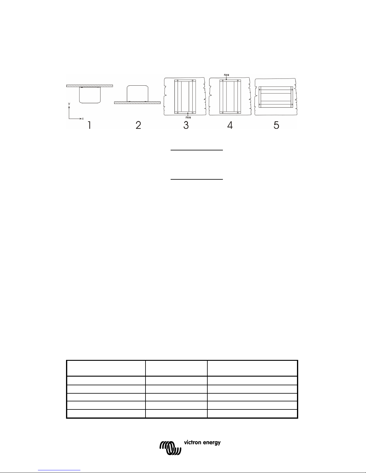
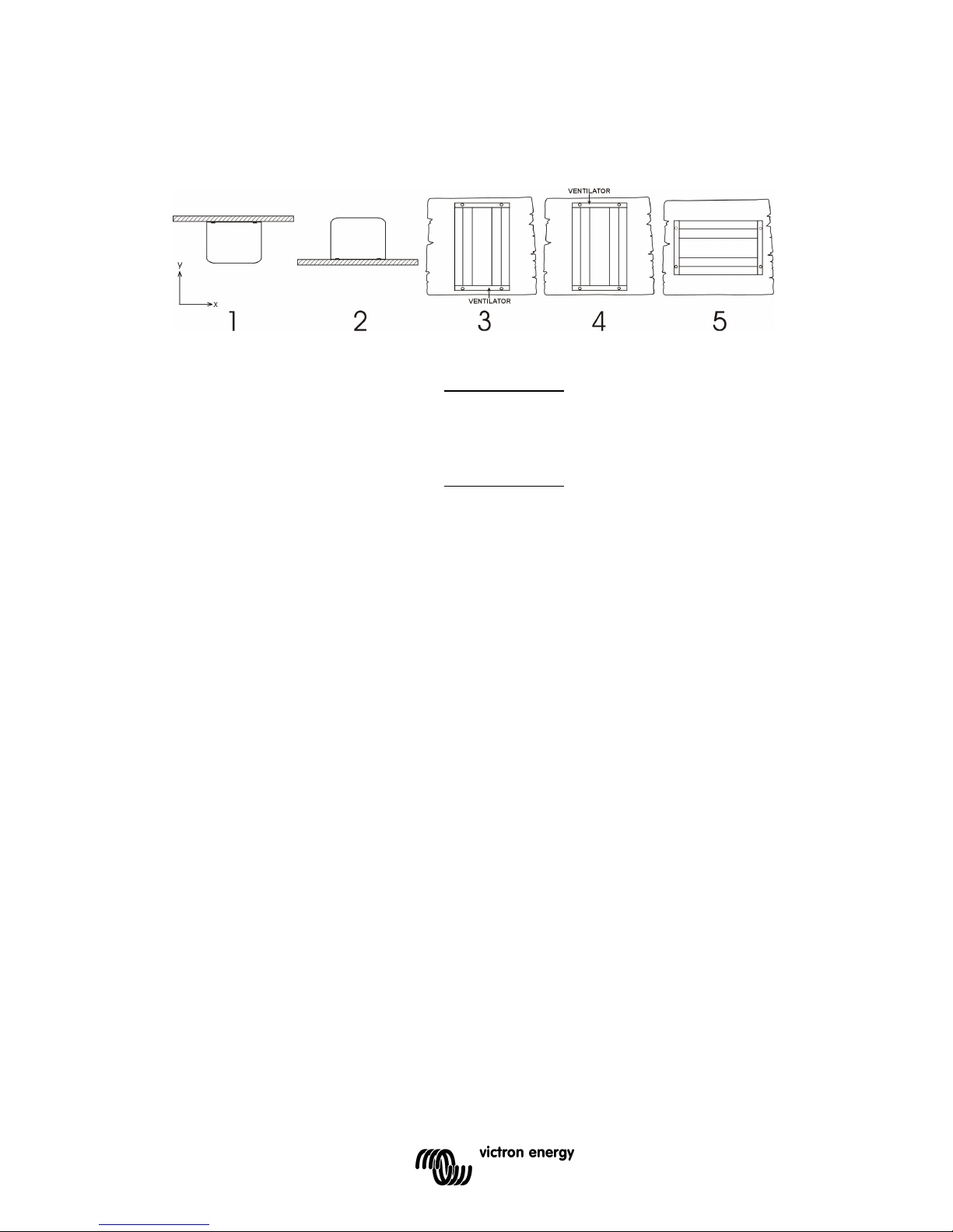
1.1 Location of the inverter
1 Ceiling mounting (inverted). Not recommended
2. Base mounting.
OK
3 Vertical wall mounting, fan at
bottom.
OK
(beware of small objects falling through
the ventilation openings on top).
4 Vertical wall mounting, fan on
top.
Not recommended
5 Horizontal wall mounting.
OK
For best operating results, the inverter should be placed on a flat surface. To ensure a
trouble free operation of the inverter, it must be used in locations that meet the
following requirements:
a) Avoid any contact with water. Do not expose the inverter to rain or moisture.
b) Do not place the unit in direct sunlight. Ambient air temperature should be
between -20 °C and 40 °C (humidity < 95% non condensing). Note that in
extreme situations the inverter’s case temperature can exceed 70 °C.
c) Do not obstruct the airflow around the inverter. Leave at least 10
centimetres clearance around the inverter. When the inverter is running too
hot, it will shut down. When the inverter has reached a safe temperature
level the unit will automatically restart again.
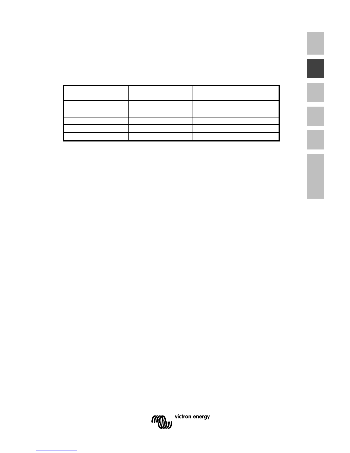
1.2 Battery requirements
For correct operation, the battery voltage should be between 0.88xVnom and
1.25xVnom where Vnom is 12V or 24V depending on the model, and must be able to
supply sufficient current to your inverter. The following table displays the
recommended battery capacity per inverter type :
Inverter type : Iin at Pnom : Recommended battery
capacity:
Ph 12/180 15 Adc
≥
60Ah
Ph 24/180 7,5 Adc
≥
30Ah
Ph 12/350 30 Adc
≥
100Ah
Ph 24/350 15 Adc
≥
60Ah
Page 7
3
EN NL FR DE ES Appendix
The inverter shuts down when the battery voltage is below 0.88xVnom or above
1.3xVnom.
Shut down and restart voltages: see technical data.
1.3 Connection to the battery
The inverters are equipped with two wires with a length of 1.5 meters. If it is
unavoidable to extend these wires, use a wire gauge of at least 1.5 times larger than
the ones supplied with the inverter. Maximum recommended battery wire length is
approx. 3 meters.
1.3.1 General precautions when working with batteries
1. Working in vicinity of a lead acid battery is dangerous. Batteries can
generate explosive gases during operation. Never smoke or allow a spark
or flame in the vicinity of a battery. Provide sufficient ventilation around the
battery.
2. Wear eye and clothing protection. Avoid touching eyes while working near
batteries. Wash your hands when done.
3. If battery acid contacts skin or clothing, wash immediately with soap and
water. If acid enters eye, immediately flood eye with running cold water for
at least 15 minutes and get medical attention immediately.
4. Be careful when using metal tools in vicinity of batteries. Dropping a metal
tool onto a battery might cause a short-circuit battery and, possibly an
explosion.
5. Remove personal metal items such as rings, bracelets, necklaces, and
watches when working with a battery. A battery can produce a short-circuit
current high enough to melt a ring or the like to metal, causing severe
burns.
CAUTION
The red wire must be connected to the positive
(+) terminal and the black wire to the negative (-)
terminal of the battery.
Reverse polarity connection of the battery wires can
damage the inverter!
Damage caused by reversed polarity is not covered
by the warranty. Make sure the power switch is in the
OFF ‘0’ position before connecting the battery.
1.4 Connecting the load
Before you connect your appliance(s) to the inverter, always check it’s maximum
power consumption. Do not connect appliances to the inverter needing more than the
nominal power rating of the inverter continuously. Some appliances like motors or
pumps, draw large inrush currents in a start-up situation. In such circumstances, it is
possible that the start-up current exceeds the over current trip level of the inverter. In
this case the output voltage will quickly decrease to limit the output current of the
inverter. If the over current trip level is continuously exceeded, the inverter will shut
down and restart within 18 seconds. In this case it is advisable to disconnect the
appliance from the inverter, since it requires too much power to be driven by this
Page 8
4
inverter. Note that at higher ambient temperature levels, the overload capacity of the
inverter is reduced.
1.5 Turning the inverter on
When all the above requirements are checked and satisfied and all connections are
made, it’s time to turn on your Phoenix inverter by pushing the power switch to the '
On ' position.
WARNING
IF THE INVERTER SWITCHES TO AN ‘ERROR
MODE’ (SEE CHAPTER 2.1) DUE TO AN
OVERLOAD OR SHORT CIRCUIT, THE INVERTER
WILL AUTOMATICALLY RESTART AFTER ABOUT
18 SECONDS.
In case of an over-temperature error, the inverter will
automatically restart after it has reached an
acceptable temperature
NEVER TOUCH THE AC CONNECTIONS WHEN
THE INVERTER IS STILL RUNNING IN AN ERROR
MODE!
WARNING
The builT in large electrolytic capacitors can hold
significant DC voltage when the batteries are
disconnected.
To avoid sparks or short inverter operation, it is
advisable to switch on the inverter for 10 seconds
after battery disconnection, before you transport the
inverter.
WARNING
WHEN CONNECTING MORE THAN ONE
APPLIANCE TO THE INVERTER, IN
COMBINATION WITH A COMPUTER, NOTE
THAT IF ONE OF THE APPLIANCES DRAWS A
HIGH START CURRENT, IT CAN CAUSE YOUR
COMPUTER TO REBOOT DUE TO A SUDDEN
VOLTAGE DROP.
CAUTION
Never connect the inverter’s output to the AC
distribution grid, SUCH AS your household AC
wall outlet. IT WILL DAMAGE THE INVERTER.
Page 9
5
EN NL FR DE ES Appendix
2. Troubleshooting
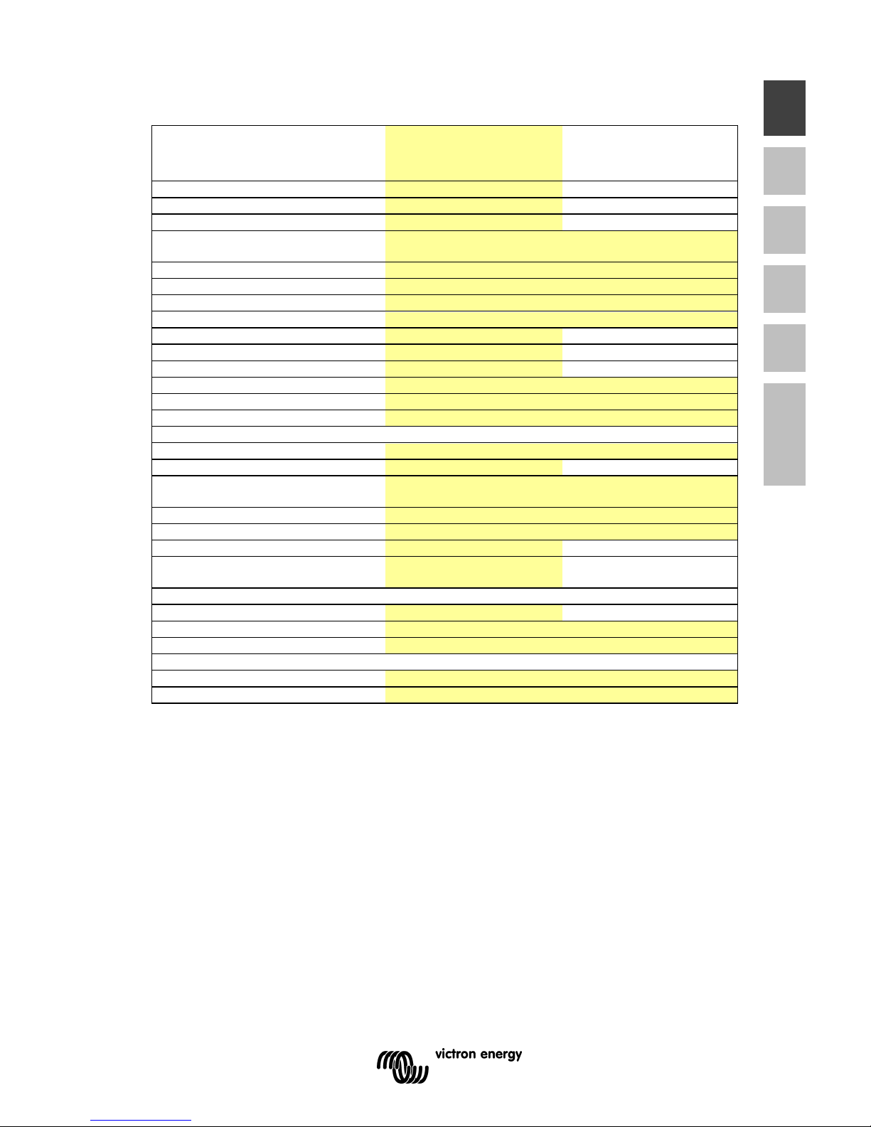
2.1 The flash sequence table
Your Phoenix inverter is equipped with a self-diagnosis system, to inform you about
the cause of inverter shut down.
In the table below you can find out what kind of flashing sequence belongs to which
error.
2.2 Troubleshooting guidelines
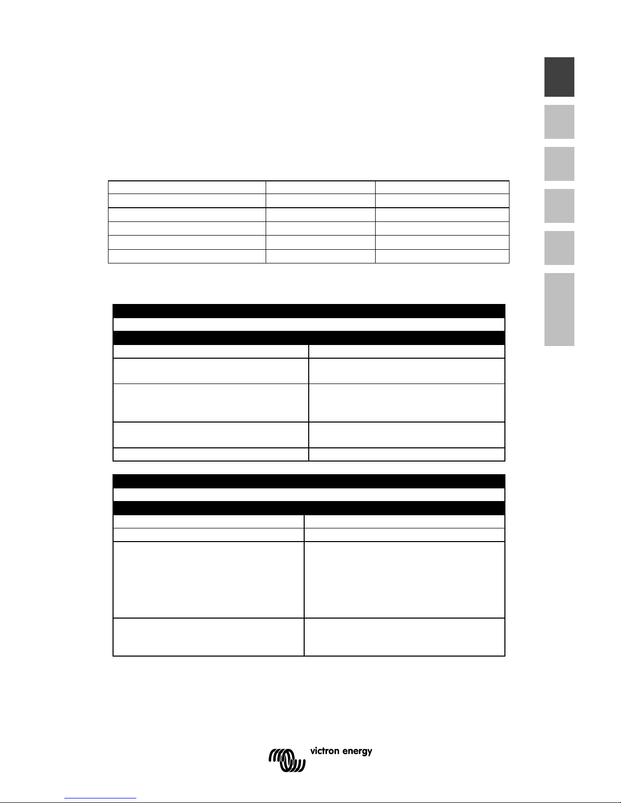
PROBLEM : Inverter is not working (LED OFF)
Possible cause : Remedy :
Power switch in OFF position. Push the power switch to the ON
position.
Poor contact between the inverter’s
battery wires and the battery terminals.
Clean battery terminals or inverter wire
contacts. Tighten battery terminal
screws.
Blown inverter fuse. The inverter has to be returned for
service.
Very poor battery condition. Replace battery.
PROBLEM : ‘Battery voltage too low or too high’ error keeps on appearing
Possible cause :
Remedy :
Poor battery condition. Replace battery or charge it first.
Poor connection or inadequate wiring
between battery and inverter,
resulting in too much voltage drop.
When extending the battery wires of the
inverter make sure you use the correct
wire gauge (≥ 1.5 times larger than the
fixed battery wires). It’s not advisable to
extend the battery wires to more than 3
meters.
General failure in your electrical
system (in case of no direct battery
connection).
Check your electrical system or consult
an electrical engineer to check it for
you.
LED
Status
Solid green
OK
Red, blinking fast
−−−− −−−− −−−− −−−− −−−− −−−− −−−− −−−−
Over voltage
Red, blinking slow
Under voltage
Red, intermittent blinking
−−−− −−−−
−−−− −−−−
−−−− −−−−
Over temperature
Solid red
Overload
Page 10
6
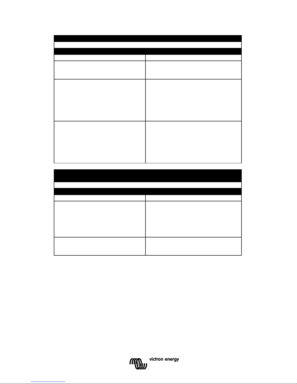
PROBLEM
: ‘Overloaded or shorted output’ error keeps on appearing
Possible cause :
Remedy :
Inverter is overloaded. Make sure that the total power rating of
the connected equipment is lower than
the nominal inverter power rating.
Connected equipment features a bad
power factor
Reduce the required power
consumption of the load. Please note
that, for example, a computer load
features a bad power factor, which
causes a reduction of the maximum
output power of the inverter by approx.
20%.
Connected equipment causes a short
circuit at the inverter’s output.
Make sure that the connected
equipment is not broken or
malfunctioning. Check if the AC power
cord between the inverter and the
connected equipment is OK. Any
physical damage on the power cord can
produce a short circuit. Be careful!.
PROBLEM : ‘Inverter temperature too high. Cooling down’ error keeps on
appearing
Possible cause :
Remedy :
Airflow around the inverter is
obstructed.
Make sure there is at least 10
centimetres of clearance around the
inverter. Remove any items placed on
or over the inverter. Keep the inverter
away from direct sunlight or heat
producing equipment.
Too high ambient temperature. Move the inverter to a cooler place or
provide additional cooling by an
external fan.
Note: Don’t turn-off the inverter when it’s operating in an ‘Inverter temperature too
high. Cooling down’ error. The inverter needs this error time to cool down.
If none of the above remedies helps to solve the problem you encounter, contact your
local Victron Energy distributor for further help and/or possible repair of your inverter.
Do not open the inverter yourself, there are dangerous high voltages present inside.
Opening the inverter will directly void your 12 months warranty period.
Page 11
7
EN NL FR DE ES Appendix
3. Technical data
3. Description of the Digital Multi Control panel
Phoenix Inverter
12 Volt
24 Volt
48 Volt
12/180
24/180
48/180
12/350
24/350
48/350
Cont. AC power at 25 °C (VA)
(3)
180 350
Cont. power at 25 °C / 40 °C (W) 175 / 150 300 / 250
Peak power (W) 350 700
Output AC voltage / frequency
110VAC +/- 5% or 230VAC +/- 3%
50Hz or 60Hz +/- 0,1%
Input voltage range (V DC) 10,5 - 15,0 / 21,0 - 30,0 / 42,0 - 60,0
Low battery alarm (V DC) 11,0 / 22 / 44
Low battery shut down (V DC) 10,5 / 21 / 42
Low battery auto recovery (V DC) 12,5 / 25 / 50
Max. efficiency 12 / 24 / 48 V (%) 87 / 88 / 89 89 / 89/ 90
Zero-load power 12 / 24 / 48 V (W) 2,6 / 3,8 / 4,0 3,1 / 5,0 / 6,0
Zero-load power in Power Saving mode
n. a. n. a.
Protection
(2)
a - e
Operating temperature range -20 to +50°C (fan assisted cooling)
Humidity (non condensing) max 95%
ENCLOSURE
Material & Colour aluminium (blue Ral 5012)
Battery-connection 1) 1)
Standard AC outlets
IEC-320 (IEC-320 plug included), Schuko,
or Nema 5-15R
Other outlets (at request) United Kingdom, Australia/New Zealand
Protection category IP 20
Weight (kg / lbs) 2,7 / 5,4 3,5 / 7,7
Dimensions (hxwxd in mm)
(hxwxd in inches)
72x132x200
2.8x5.2x7.9
72x155x237
2.8x6.1x9.3
ACCESSORIES
Remote control panel n. a. n. a.
Remote on-off switch Two pole connector
Automatic transfer switch Filax
STANDARDS
Safety EN 60335-1
Emission / Immunity EN55014-1 / EN 55014-2
1. Battery cables of 1.5 meter (12/180 with cigarette plug)
2. Protection
a. Output short circuit
b. Overload
c. Battery voltage too high
d. Battery voltage too low
e. Temperature too high
3. Non linear load, crest factor 3:1
Page 12

Page 13

1
EN NL FR DE ES Appendix
Inleiding
Victron Energy heeft op het gebied van het ontwikkelen en produceren van
elektrische energievoorzieningsystemen internationale bekendheid verworven.
Victron Energy heeft deze wereldfaam met name te danken aan de voortdurende
inspanningen van de ontwikkelingsafdeling. Deze afdeling houdt zich bezig met
onderzoek naar en realisatie van mogelijkheden om nieuwe technologieën die zinvolle
technische en economische bijdragen leveren, in de producten van Victron Energy te
implementeren.
Deze beproefde filosofie heeft geleid tot de ontwikkeling van een complete serie
energieverzorgende apparatuur waarin de laatste technische ontwikkelingen zijn
verwerkt. De apparatuur van Victron Energy voldoet aan de strengste eisen.
Victron Energy levert kwalitatief hoogwaardige wisselstroomvoor-zieningen voor
gebruik op plaatsen waar geen permanente aansluiting op het elektriciteitsnet (230 of
115 Vac) voorhanden is.
Met behulp van de apparatuur van Victron Energy kan een automatisch ‘stand alone’
energievoorzieningsysteem worden gecreëerd. Maak voor de configuratie naast
krachtige accu’s gebruik van een omvormer en een acculader.
De apparatuur van Victron Energy is geschikt voor alle soorten elektrische apparaten
voor huishoudelijk, technisch, en industrieel gebruik, inclusief storingsgevoelige
instrumenten. De Victron Energy systemen zijn hoogwaardige energiebronnen die
borg staan voor een storingsvrije werking.
Victron Energy Phoenix omvormer
Deze gebruiksaanwijzing beschrijft de installatie, de werking en de praktische
toepassing van de Ph 12/180, Ph 24/180, Ph 48/350, Ph 12/350, Ph 24/350 en de
Ph 48/350 sinusomvormers. Bovendien wordt in deze gebruiksaanwijzing ingegaan
op de beveiligingsvoorzieningen en de technische specificaties van de Phoenix
omvormer.
N.B. : in deze gebruiksaanwijzing wordt in sommige gevallen gebruik gemaakt van de
afkorting ‘Ph’ in plaats van Phoenix .
Page 14
2
1. Installatie
1.1 Plaatsing van de omvormer
1 Plafond montage Niet aanbevolen
2 Vloer montage
OK
3 Verticale muur montage,
ventilator onder
OK
(pas op kleine objecten die door de
ventilatie openingen aan de bovenkant
kunnen vallen)
4 Verticale muur montage,
ventilator boven
Niet aanbevolen
5 Horizontale muur montage
OK
Om een probleemloze werking van de omvormer te kunnen garanderen, moet de
locatie waarin deze wordt geïnstalleerd aan de volgende eisen voldoen:
a) Vermijdt elk contact met water. Stel de omvormer niet bloot aan regen of
mist.
b) Plaats de omvormer niet in direct zonlicht.
De omgevingstemperatuur moet tussen -20 °C en 40 °C liggen
(luchtvochtigheid < 95% niet condenserend). In extreme situaties kan de
behuizing van de omvormer een temperatuur bereiken van meer dan 70 °C.
c) Vermijd obstructie van de luchtstroming rond de omvormer. Laat minstens
10 centimeter ruimte vrij rond de omvormer. Wanneer de omvormer een te
hoge temperatuur heeft bereikt, zal deze zichzelf uitschakelen. Als de
omvormer is afgekoeld tot een acceptabele temperatuur schakelt deze
weer in.
Page 15
3
EN NL FR DE ES Appendix
1.2 Accu eisen
Voor een correcte werking moet de accuspanning tussen 0,88xVnom en 1,25xVnom
liggen, Vnom is afhankelijk van het model 12V of 24V. De accu moet in staat zijn om
voldoende stroom te kunnen leveren aan de omvormer. De volgende tabel geeft de
geadviseerde accu capaciteit weer:
Omvormer model: Iin bij Pnom : Geadviseerde
accu capaciteit:
Ph 12/180 15 Adc
≥
60Ah
Ph 24/180 7,5 Adc
≥
30Ah
Ph 12/350 30 Adc
≥
100Ah
Ph 24/350 15 Adc
≥
60Ah
De omvormer schakelt uit wanneer de accuspanning onder 0,88xVnom of boven
1,3xVnom ligt.
Start en stop spanningen: zie technische gegevens.
1.3 Het aansluiten van de accu
De omvormers zijn uitgerust met twee accu aansluit kabels met een lengte van 1,5
meter. Als verlenging van de accukabels onvermijdelijk is, moet een draad diameter
worden gebruikt van minstens 1,5 keer de diameter van de vaste omvormer kabels.
De maximum aanbevolen accukabel lengte is circa 3 meter.
1.3.1 Voorzorgsmaatregelen omtrent het werken met accu's
1. Werken in de nabijheid van accu's kan gevaarlijk zijn. Accu's kunnen
explosieve gassen produceren. Vermijd roken, vonken of open vuur in de
buurt van accu's. Zorg voor voldoende ventilatie.
2. Draag oog en kleding bescherming. Vermijd het aanraken van de ogen
wanneer er met accu's gewerkt wordt. Was de handen na het werken met
accu's.
3. Als accuzuur in contact komt met de huid of kleding, was dit dan
onmiddellijk af met water en zeep. Als het zuur in contact komt met de
ogen, spoel dan onmiddellijk met koud stromend water. Doe dit gedurende
15 minuten en roep zo nodig medische hulp in.
4. Wees voorzichtig met het gebruik van metalen gereedschap in de buurt van
accu's. Het laten vallen van metalen objecten op de accu kan kortsluiting en
explosie gevaar opleveren.
5. Verwijder persoonlijke zaken zoals ringen, armbanden, horloges en
kettingen wanneer met accu's gewerkt wordt. Accu's kunnen
kortsluitstromen veroorzaken die metalen objecten volledig kunnen laten
smelten met ernstige brandwonden tot gevolg.
Page 16

4
DE RODE DRAAD MOET A
ANGESLOTEN WORDEN
OP DE POSITIEVE (+) ACCUKLEM EN DE ZWARTE
DRAAD OP DE NEGATIEVE (-) ACCUKLEM.
Verkeerd om aansluiten van de accukabels kan de
omvormer beschadigen!
Schade ontstaan door het verkeerd om aansluiten van de
accukabels valt niet binnen de garantie. Zorg ervoor dat
de aan/uit schakelaar in de ‘0’ positie staat voordat u de
accu aansluitingen maakt.
1.4 Aansluiting van de belasting
Controleer voordat u uw apparatuur op de omvormer uitgang aansluit, of het totale
stroomverbruik van de betreffende apparaten niet hoger is dan de nominale
uitgangsstroom van de omvormer. Sommige apparaten zoals elektrisch gereedschap
en pompen hebben een hoge inschakelstroom bij het opstarten. In dit geval is het
mogelijk dat zo'n inschakelstroom de interne stroombeveiliging van de omvormer
aanspreekt waardoor de uitgangsspanning van omvormer kortstondig daalt. Als deze
stroom beveiliging in een korte tijd een aantal keren achter elkaar wordt
aangesproken, zal de omvormer in de overbelastingsbeveiliging springen zodat de
uitgangsspanning verdwijnt. In dit geval is het raadzaam om de aangesloten belasting
te verminderen omdat deze te zwaar is voor de omvormer.
Na ca. 18 seconden start de omvormer automatisch weer op. Bij hogere
omgevingstemperaturen daalt de overbelastingscapaciteit van de omvormer.
WANNEER ER MEER DAN ÉÉN APPARAAT
WAARONDER EEN COMPUTER WORDT
AANGESLOTEN OP DE OMVORMER, KAN HET
VOORKOMEN DAT WANNEER ÉÉN VAN DE
APPARATEN OPSTART, DE COMPUTER GERESET
WORDT VANWEGE EEN PLOTSELINGE
SPANNINGSVAL.
SLUIT DE UITGANG VAN DE OMVORMER NOOIT AAN
OP HET VASTE ELEKTRICITEITSNET VIA BIJV. EEN
WANDCONTACTDOOS. HIERDOOR KAN DE
OMVORMER ZWAAR BESCHADIGEN.
Page 17

5
EN NL FR DE ES Appendix
1.5 Activeren van de omvormer
Wanneer aan alle eerder genoemde eisen is voldaan en alle
aansluitingen zijn gemaakt, kan uw Phoenix omvormer worden
ingeschakeld door de aan/uit schakelaar in de ' On ' positie te zetten.
WANNEER DE OMVORMER IN EEN ‘ERROR MODE
’
SPRINGT (ZIE HOOFDSTUK 2.1) VANWEGE
OVERBELASTING OF KORTSLUITING, ZAL DE
OMVORMER WEER AUTOMATISCH OPSTARTEN NA
CIRCA 18 SEC.
In het geval van een temperatuur error, zal de omvormer
pas weer automatisch opstarten nadat er een
acceptabele omvormer temperatuur is bereikt..
VERRICHT NOOIT WERKZAAMHEDEN AAN DE AC
AANSLUITINGEN WANNEER DE OMVORMER IN EEN
‘ERRORMODE’ WERKT!
DE GROTE INTERNE CONDENSATOR KAN OP
SPANNING BLIJVEN STAAN WANNEER DE ACCU’S
ZIJN AFGEKOPPELD.
Om vonken of korte omvormer werking te voorkomen, is
het raadzaam om de omvormer circa 10 seconden aan te
zetten nadat deze is losgekoppeld van de accu’s. Hierna
kunt u de omvormer veilig transporteren.
Page 18

6
2. Het oplossen van storingen
2.1 Optische alarmen
Uw Phoenix omvormer is uitgerust met een zelf diagnose systeem om u te kunnen
informeren over de oorzaak van een automatische omvormer uitschakeling.
In de volgende tabel kunt u zien welk error/alarm type er bij welk LED knipper patroon
hoort.
LED
Status
Groen, continu
OK
Rood,
snel knipperend
−−−− −−−− −−−− −−−− −−−− −−−− −−−− −−−−
Overspanning
Rood, traag knipperend
Onderspanning
Rood, onderbroken
−−−− −−−−
−−−− −−−−
−−−− −−−−
Overtemperatuur
Rood, continu
Overbelasting
2.2 Storingen met mogelijke oplossingen
PROBLEEM : Omvormer werkt niet (LED is uit)
Mogelijke oorzaak : Remedie :
Aan/uit schakelaar staat in de UIT
(OFF) positie.
Druk deze schakelaar in de AAN (ON)
positie.
Slecht contact tussen de omvormer
accukabels en de accupolen.
Maak de accupolen en/of draadcontacten
schoon. Draai de bevestigingsschroeven
goed aan.
Zekering defect. De omvomer moet geretourneerd worden
voor service.
Zeer slechte accu conditie. Herlaad of vervang de accu.
PROBLEEM : ‘Accuspanning te laag of te hoog’ alarm blijft optreden
Mogelijke oorzaak : Remedie :
Slechte accu conditie. Herlaad of vervang de accu.
Slechte verbinding of verkeerde
bedrading tussen omvormer en accu,
resulterend in een te hoog
spanningsverlies.
Ga alle verbindingen na. Als de
accukabels verlengd zijn moet de juiste
draaddikte worden gebruikt (≥ 1.5 keer de
bijgeleverde draad oppervlakte). Het
wordt niet aanbevolen de accukabels tot
meer dan circa 3 meter te verlengen.
Een fout in uw elektrische systeem (in
het geval van een niet directe
verbinding met de accu).
Controleer uw elektrische systeem of
raadpleeg hiervoor een elektrotechnicus.
Page 19

7
EN NL FR DE ES Appendix
PROBLEEM : ‘Uitgang overbelast of kortgesloten’ alarm blijft optreden
Mogelijke oorzaak : Remedie :
Omvormer is overbelast. Controleer of het totale vermogen van de
aangesloten belasting niet het nominale
vermogen van de omvormer overschrijdt.
Aangesloten belasting heeft een
slechte power factor (cosϕ bij
sinusvormige stromen).
Reduceer de grootte van de belasting. N.B.
een computer bijvoorbeeld, heeft een
slechte power factor waardoor het
maximale werkelijke uitgangssvermogen
van de omvormer met ca. 20% daalt.
Aangesloten belasting veroorzaakt
een kortsluiting aan de uitgang van
de omvormer.
Controleer of de aangesloten belasting niet
defect is inclusief het netsnoer tussen de
belasting en de omvormer. Een fysiek
beschadigd netsnoer kan een kortsluiting
veroorzaken. Wees voorzichtig in dit soort
omstandigheden!
PROBLEEM : ‘Omvormer temperatuur te hoog’ alarm blijft optreden
Mogelijke oorzaak : Remedie :
Luchtstroom rond de omvormer is
geblokkeerd.
Zorg voor minstens 10 centimeter ruimte
om de omvormer. Verwijder eventuele
voorwerpen die op of over de omvormer
liggen. Houd de omvormer uit direct
zonlicht of warmte producerende
apparatuur.
Te hoge omgevingstemperatuur. Verplaats de omvormer naar een koelere
plaats of zorg voor extra koeling met een
extra externe ventilator.
N.B.: Zet de omvormer niet uit wanneer deze werkt in een 'Omvormer temperatuur te
hoog' alarm. De omvormer heeft deze tijd nodig om af te koelen en laat daarom ook
de interne ventilator draaien.
Als géén van de bovengenoemde remedies een oplossing bieden bij de problemen
die u ondervindt, is het raadzaam om contact op te nemen met uw locale Victron
Energy dealer voor verdere hulp en/of eventuele reparatie. Open zelf nooit de
omvormer, er kunnen gevaarlijk hoge spanningen aanwezig zijn in de omvormer!
Tevens zal in dat geval de 12 maanden garantie periode komen te vervallen.
Page 20

8
3. Technische gegevens
Phoenix Inverter
12 Volt
24 Volt
48 Volt
12/180
24/180
48/180
12/350
24/350
48/350
Continu vermogen bij 25°C (VA)
(3)
180 350
Continu vermogen bijt 25°C / 40°C (W) 175 / 150 300 / 250
Peak power (W) 350 700
Uitgangsspanning en frequentie
110VAC +/- 5% of 230VAC +/- 3%
50Hz of 60Hz +/- 0,1%
Ingangsspanning bereik (V DC) 10,5 - 15,0 / 21,0 - 30,0 / 42,0 - 60,0
Onderspanning alarm (V DC) 11,0 / 22 / 44
Afschakelspanning (V DC) 10,5 / 21 / 42
Startspanning (V DC) 12,5 / 25 / 50
Maximaal rendement 12 / 24 / 48 V (%) 87 / 88 / 89 89 / 89/ 90
Nullast 12 / 24 / 48 V (W) 2,6 / 3,8 / 4,0 3,1 / 5,0 / 6,0
Nullast in Power Saving mode (W)
Beveiligingen
(2)
a - e
Temperatuur bereik -20 to +50°C (fan assisted cooling)
Vocht (niet condenserend) max 95%
BEHUIZING
Materiaal & kleur aluminium (blauw Ral 5012)
Accu-aansluiting 1) 1)
230 V AC-aansluiting
IEC-320 (IEC-320 stekker bijgeleverd), Schuko, of
Nema 5-15R
Beschermklasse IP 20
Gewicht (kg) 2,7 / 5,4 3,5 / 7,7
Afmetingen (hxbxd in mm)
(hxwxd in inches)
72x132x200
2.8x5.2x7.9
72x155x237
2.8x6.1x9.3
ACCESSOIRES
Afstandbediening paneel nee nee
Afstandbediening (aan/uit schakelaar) Dubbelpolige connector
Omschakelautomaat Filax
NORMEN
Veiligheid EN 60335-1
Emissie / Immuniteit EN55014-1 / EN 55014-2
1. 2 kabels van 1,5 meter (12/180 voorzien van stekker voor sigaretten aansteker
2. Beveiligingen
a. Kortsluiting
b. Overbelasting
c. Accuspanning te hoog
d. Accuspanning te laag
e. Temperatuur te hoog
3. Niet lineaire belasting, crest faktor 3:1
Page 21

1
EN NL FR DE ES Appendix
Introduction
Victron Energy a acquis une renommée internationale dans le domaine du
développement et de la production de systèmes autonomes d'alimentation électrique .
Victron Energy doit plus particulièrement cette renommée mondiale aux efforts
permanents de son département Recherche et Développement. Celui-ci étudie et
concrétise la mise en œuvre de nouvelles technologies qui contribuent techniquement
et économiquement aux performances des produits de Victron Energy.
Cette philosophie qui a fait ses preuves a permis le développement d'une gamme très
complète d'appareils de conversion d'énergie qui intègrent les technologies les plus
avancées. Les appareils produits par Victron Energy répondent aux exigences les
plus sévères. Victron Energy fournit des équipements d'alimentation en courant
alternatif qui s'utilisent là où il n'existe pas de raccordement au réseau électrique (230
/ 115 Vac).
Les appareils de Victron Energy permettent de créer un système d'alimentation
électrique autonome et automatique, composé d'un chargeur, de batteries puissantes
et d'un convertisseur.
L'appareillage de Victron Energy convient à tous les types d'appareils électriques à
usage ménager, technique et industriel, notamment aux instruments sensibles aux
perturbations . Les systèmes Victron Energy sont des sources d'énergie de grande
qualité qui garantissent un fonctionnement fiable et durable .
Victron Energy Phoenix convertisseur
Ce mode d'emploi décrit l'installation, le fonctionnement et l'application pratique des
convertisseurs sinusoïdaux Phoenix 12/180, Phoenix 24/180, Phoenix 48/180,
Phoenix 12/350, Phoenix 24/350 et Phoenix 48/350. De plus, ce mode d'emploi
évoque les précautions de sécurité et les spécifications techniques du convertisseur
Phoenix.
N.B.: dans certains cas, ce mode d'emploi utilise l'abréviation 'Ph' au lieu du nom
complet Phoenix. Te terme "Charge" est utilisé dans le sens de consommation en
sortie, à ne pas confondre avec la charge d'une batterie.
Page 22

2
1. Installation
1.1 Installation du convertisseur
1 Montage au plafond Déconseillé
2 Montage au sol
OK
3 Montage vertical sur une
cloison avec ventilateur vers
le bas
OK
(attention aux petits objets qui pourraient
tomber dans les ouvertures de ventilation)
4 Montage vertical sur une
cloison avec ventilateur vers
le haut
Déconseillé
5 Montage horizontal sur une
cloison
OK
Pour garantir le fonctionnement correct du convertisseur, son emplacement doit
répondre aux exigences suivantes:
a) évitez tout contact avec l'eau. N'exposez pas le convertisseur à la pluie ou
au brouillard;
b) ne placez pas le convertisseur dans un endroit exposé directement au
soleil;
la température ambiante doit être de -20 °C à 40 °C (humidité de l'air <95%
sans ruissellement); dans des situations extrêmes, le boîtier du
convertisseur peut atteindre une température de plus de 70 °C;
c) évitez toute obstruction de la circulation de l'air autour du convertisseur;
laissez au moins 10 cm d'espace libre autour du convertisseur; lorsque le
convertisseur atteint une température trop élevée, il s'éteint
automatiquement; lorsque la température du convertisseur devient à
nouveau acceptable, il redémarre automatiquement.
Page 23

3
EN NL FR DE ES Appendix
1.2 Exigences relatives à la batterie
Pour un fonctionnement correct, la tension de la batterie doit varier de 0,88xVnom à
1,25xVnom (Vnom dépend du modèle 12V ou 24V). La batterie doit pouvoir fournir
suffisamment d'électricité au convertisseur. Le tableau suivant indique la capacité
conseillée de la batterie:
Modèle de
convertisseur
Ientrée pour Pnom : Capacité batterie
conseillée:
Ph 12/180 15 Adc
≥
60Ah
Ph 24/180 7,5 Adc
≥
30Ah
Ph 12/350 30 Adc
≥
100Ah
Ph 24/350 15 Adc
≥
60Ah
Le convertisseur s’arrête quand la tension de batterie se trouve au- dessous de
0,88xVnom ou au- dessus de 1,3xVnom.
Tensions de mise en marche et d’arrêt : voir caractéristiques techniques.
1.3 Raccordement de la batterie
Les convertisseurs sinusoïdaux Phoenix sont équipés de deux câbles électriques
d'une longueur de 1,5 mètres. Si un rallongement des câbles de la batterie est
indispensable, il convient d'utiliser un câble d'au moins 1,5 fois la section des câbles
fixes du convertisseur. La longueur maximale conseillée pour les câbles vers la
batterie est d'environ 3 mètres.
1.3.1 Précautions relatives à l'utilisation de batteries
1. Travailler à proximité de batteries peut être dangereux. Les batteries
peuvent produire des gaz explosifs. Évitez de fumer, de provoquer des
étincelles ou de faire du feu avec flammes nues à proximité batteries.
Veillez à disposer d'une ventilation suffisante.
2. Portez une protection oculaire et vestimentaire. Évitez de toucher vos yeux
lorsque vous avez travaillé avec des batteries. Lavez-vous les mains
lorsque vous avez fini de travailler.
3. Si de l'acide contenu dans les batteries entre en contact avec votre peau ou
vos vêtements, lavez-les immédiatement à l'eau et au savon. Si l'acide
entre en contact avec les yeux, rincez-les immédiatement à l'eau courante.
Rincez vos yeux pendant 15 minutes et si nécessaire, faites appel à un
médecin.
4. Soyez prudent lorsque vous utilisez des outils métalliques à proximité des
batteries. Si vous laissez tomber un objet métallique sur une batterie, celuici peut provoquer un court-circuit et/ou une explosion.
5. Ne portez pas d'objets tels que bagues, bracelets, montres et chaînes
lorsque vous travaillez près de batteries. En contact avec les batteries ces
objets peuvent provoquer des court-circuits qui les feront fondre totalement
et entraîneront des brûlures graves.
Page 24

4
LE FIL ROUGE DOIT ÊTRE RACCORDE A LA BORNE
POSITIVE (+) ET LE FIL Noir A LA BORNE NÉGATIVE
(-).
Toute erreur de raccordement des câbles vers la batterie
peut provoquer des dégâts!
Les dégâts provoqués par un raccordement erroné des
câbles vers la batterie ne sont pas couverts par la
garantie. Veillez à ce que l'interrupteur se trouve en
position '0' avant de procéder aux raccordements de la
batterie.
1.4 Raccordement de la charge
Avant de raccorder votre appareillage au convertisseur, vérifiez si la puissance
électrique totale des appareils en question n'est pas supérieure à puissance de sortie
nominale du convertisseur. Certains appareils tels les outils électriques et des
pompes ont une très forte consommation électrique au démarrage. Dans ce cas, il se
peut qu'un tel appel de courant de démarrage déclenche la protection interne du
convertisseur, ce qui fait momentanément chuter sa tension de sortie. Si cette
protection est sollicitée rapidement et à plusieurs reprises, le convertisseur se mettra
en sécurité "surcharge" et sa tension de sortie sera coupée. Dans ce cas, la charge
raccordée au convertisseur est trop importante et nous vous conseillons de la réduire.
Après environ 18 secondes, le convertisseur redémarre automatiquement. Si la
température ambiante est élevée, la capacité de surcharge du convertisseur diminue.
SI VOUS RACCORDEZ AU CONVERTISSEUR
PLUSIEURS APPAREILS, DONT UN ORDINATEUR, IL
SE PEUT QUE LORSQUE L'UN DE CES APPAREILS
EST MIS EN ROUTE, L'ORDINATEUR SOIT
PERTURBÉ ET RELANCÉ DU FAIT D'UNE SOUDAINE
CHUTE DE TENSION.
NE RACCORDEZ
JAMAIS LA SORTIE DU
CONVERTISSEUR A UNE AUTRE SOURCE
ÉLECTRIQUE (SECTEUR) . CELA POURRAIT
GRAVEMENT ENDOMMAGER LE CONVERTISSEUR.
Page 25

5
EN NL FR DE ES Appendix
1.5 Activation du convertisseur
Lorsque toutes les instructions qui précèdent sont respectées et les raccordements
sont réalisés, le convertisseur peut être mis en marche en plaçant l'interrupteur
marche/arrêt sur la position ' On '
LORSQUE LE CONVERTISSEUR PASSE EN 'MODE
DÉFAUT' (VOIR CHAPITRE 2.1) A CAUSE D'UNE
SURCHARGE OU D'UN COURT-CIRCUIT, IL
REDÉMARRE DE NOUVEAU AUTOMATIQUEMENT
APRÈS ENVIRON 18 SECONDES.
En cas de défaut lié à la température, le convertisseur ne
redémarrera automatiquement qu'après avoir atteint une
température acceptable.
N'INTERVENEZ JAMAIS SUR LES RACCORDS AC
LORSQUE LE CONVERTISSEUR EST EN MODE
DÉFAUT
LE GRAND CONDENSATEUR INTERNE PEUT
RESTER SOUS TENSION LORSQUE LES BATTERIES
SONT DÉCONNECTÉES.
Pour éviter des étincelles ou un fonctionnement bref du
convertisseur, nous vous conseillons de le mettre en
position 'marche' pendant environ 10 secondes après
l'avoir déconnecté des batteries, ceci déchargera le
condensateur. Vous pourrez alors manipuler le
convertisseur en toute sécurité.
Page 26

6
2. Diagnostic et r’esolution de pannes
2.1 Alarmes visuelles
Votre convertisseur Phoenix est équipé d'un système de diagnostic automatique qui
vous informe des causes d'un arrêt automatique suite à un défaut.
Le tableau suivant vous permet de savoir le type d'erreur ou d'alarme correspondant
à un mode de clignotement déterminé.
LED
Nature du d
é
faut
Verte
, continu
OK
Rouge, clignotant
rapidement
−−−− −−−− −−−− −−−− −−−− −−−− −−−− −−−−
Surtension
Rouge, clignotant lentement
Soustension
Rouge, intermittant
−−−− −−−−
−−−− −−−−
−−−− −−−−
Temp
érature trop
élevée
Rouge, continu
Surcharge
2.2 Pannes et solutions possibles
PROBLÈME: Le convertisseur ne fonctionne pas (LED rouge éteinte)
Cause possible: Remède:
L'interrupteur est en position ARRÊT
(0FF).
Actionnez l'interrupteur pour le mettre en
position MARCHE (ON).
Mauvais contact entre les câbles
batterie du convertisseur et les cosses
de la batterie.
Nettoyez les cosses de la batterie et/ou
les contacts. Serrez bien les vis de
fixation.
Fusible défectueux. Convertisseur doivent être renvoyés pour
réparation.
La batterie est en très mauvais état. Rechargez ou remplacez la batterie.
PROBLÈME: L'alarme 'Défaut de la tension batterie' se maintient
Cause possible: Remède:
La batterie est en mauvais état. Rechargez ou remplacez la batterie.
Les raccordements ou le câblage entre
le convertisseur et la batterie sont
mauvais et entraînent d'importantes
chutes de tension.
Vérifiez tous les raccordements. Si vous
avez rallongé les câbles vers la batterie,
vous devez utiliser la section adéquate (≥
1,5 fois le câble livré de série). Nous
déconseillons de rallonger les câbles
batterie de plus de 3 mètres environ.
Erreur dans votre système électrique
(dans le cas d'un raccordement indirect
à la batterie).
Vérifiez votre système électrique ou
consultez un électrotechnicien.
Page 27

7
EN NL FR DE ES Appendix
PROBLÈME: L'alarme 'Court-circuit ou surcharge en sortie' se maintient
Cause possible: Remède:
Le convertisseur est surchargé. Vérifiez si la puissance totale de la charge
raccordée n'excède pas la puissance
nominale du convertisseur.
La charge raccordée a un mauvais
facteur de puissance (cosϕ sur
courant sinusoïdal).
Réduisez la charge. N.B. un ordinateur par
exemple a un mauvais facteur de
puissance, ce qui entraîne une diminution
de la puissance maximale de sortie utile
d'environ 20%.
La charge raccordée provoque un
court-circuit à la sortie du
convertisseur.
Vérifiez si la charge raccordée n'est pas
défectueuse, y compris le câblage entre la
charge et le convertisseur. Un câblage
endommagé peut entraîner un court-circuit.
Dans ces circonstances, soyez prudent!
PROBLÈME: L'alarme 'Température trop élevée' se maintient
Cause possible: Remède:
Le flux d'air autour du convertisseur
est bloqué.
Veillez à laisser au moins un espace de 10
centimètres autour du convertisseur.
Supprimez éventuellement les objets qui se
trouvent sur le convertisseur. Enlevez le
convertisseur de la lumière directe du soleil
ou de la proximité d'appareils qui
produisent de la chaleur.
La température environnante est trop
élevée.
Déplacez le convertisseur dans un lieu plus
frais ou apportez un refroidissement
supplémentaire à l'aide d'un ventilateur
externe.
N.B. : N'éteignez pas le convertisseur lorsqu'il est en défaut température. Le
convertisseur a besoin de temps pour refroidir, son ventilateur fonctionne.
Si aucun des remèdes proposés n'apporte de solution à vos problèmes, nous vous
conseillons de prendre contact avec votre revendeur local Victron Energy pour obtenir
son aide et / ou pour une réparation éventuelle. N'ouvrez jamais vous-même le
convertisseur, il peut contenir des tensions dangereusement élevées! Toute tentative
d'intervention par du personnel non habilité annulera la garantie.
Page 28

8
3. Caractéristiques Techniques
Convertisseur
Phoenix
12 Volt
24 Volt
48 Volt
12/180
24/180
48/180
12/350
24/350
48/350
Puissance CA cont. à C (VA) (3) 180 350
Puissance cont. à 25 °C / 40 ºC(W)
175 / 150 300 / 250
Puissance de pointe (W)
350 700
Tension / fréquence de sortie CA
110 V CA ±5 % ou 230 V CA ±3 %
50 Hz ou 60 Hz ±0,1 %
Plage de tension d'entrée (V CC)
10,5 - 15,0 / 21,0 - 30,0 / 42,0 - 60,0
Alarme batterie basse (V CC)
11,0 / 22 / 44
Arrêt batterie basse (V CC)
10,5 / 21 / 42
Reprise auto. batterie basse (V CC)
12,5 / 25 / 50
Efficacité maxi 12 / 24 / 48 V (%)
87 / 88 / 89 89 / 89/ 90
Puissance de charge zéro 12 / 24 /
48 V (W)
2,6 / 3,8 / 4,0 3,1 / 5,0 / 6,0
Puissance de charge zéro en mode
économie d'énergie
n. a. n. a.
Protection (2)
a - e
Température de fonctionnement
-20 à +50 °C (refroidissement par ventilateur)
Humidité (sans condensation)
maxi 95%
BOÎTIER
Matériau et couleur
aluminium (bleu RAL 5012)
Raccordement batterie
1) 1)
Prises CA standard
IEC-320 (fiche IEC-320 fournie),
Schuko ou Nema 5-15R
Autres prises (sur demande)
Royaume-Uni, Australie / Nouvelle Zélande
Degré de protection
IP20
Poids (kg/lbs)
2,7 / 5,4 3,5 / 7,7
Dimensions (HxLxP en mm)
(HxLxP en pouces)
72x132x200
2,8x5,2x7,9
72x155x237
2.8x6.1x9.3
ACCESSOIRES
Tableau de commande à distance
NA NA
Interrupteur marche/arrêt à distance
Connecteur à deux pôles
Commutateur automatique
Filax
NORMES
Sécurité
EN 60335-1
Émission/Immunité
EN55014-1 / EN 55014-2
1. Câbles batterie de 1,5 mètres (12/180 avec fiche allume-cigare)
2. Protection
a. Court-circuit en sortie
b. Surcharge
c. Tension de batterie trop haute
d. Tension de batterie trop basse
e. Température trop élevée
3. Charge non linéaire, facteur de crête 3:1
Page 29

1
EN NL FR DE ES Appendix
Einleitung
Victron Energy ist auf dem Gebiet der Entwicklung und der Produktion von
elektrischen Energieversorgungssystemen international bekannt. Victron Energy hat
diesen Ruf insbesondere den ständigen Anstrengungen seiner Entwicklungsabteilung
zu danken. Diese ist stets bestrebt, neuste Technologien wirtschaftlich sinnvoll in die
Produkte von Victron Energy zu implementieren.
Diese bewährte Philosophie führte zur Entwicklung einer kompletten Serie von
Stromversorgungsgeräten, die alle dem neusten Stand der Technik und strengsten
Vorschriften entsprechen.
Victron Energy liefert qualitativ hochwertige Wechselstromversorgungsanlagen für
den Einsatz an Orten, wo kein permanenter Anschluss an das Stromnetz
(230V/115V) vorhanden ist.
Mit Hilfe eines Victron Energy Sinus Wechselrichters, eines Ladegeräts und nicht
zuletzt einer Batterie mit ausreichender Kapazität kann eine völlig autonome
Energieversorgung aufgebaut werden.
Unsere Geräte werden für unzählige Anwendungen sowohl an Land, als auch auf
Schiffen und überall dort, wo eine mobile 230V/115V Stromversorgung notwendig ist,
eingesetzt.
Die Geräte von Victron Energy sind für alle Arten von elektrischen Verbrauchern in
Haushalt, Technik und Industrie, inklusive empfindlicher Instrumente geeignet. Victron
Energiesysteme sind hochwertige Energiequellen, die einen störungsfreien Betrieb
garantieren.
Victron Energy Phoenix Sinus-Wechselrichter
Diese Bedienungsanleitung beschreibt die Installation, den Betrieb und die praktische
Anwendung von Ph 12/180, Ph 24/180, Ph 48 180, Ph 12/350, Ph 24/250 und Ph
48/350 Sinus Wechselrichtern. Darüber hinaus wird in dieser Bedienungsanleitung
auf den sicheren Umgang mit und die technischen Spezifikationen der Phoenix Sinus
Wechselrichter eingegangen.
Anmerkung: In dieser Bedienungsanleitung wird in einigen Fällen die Abkürzung "Ph"
anstelle von Phoenix verwendet.
Page 30

2
1. Installation
1.1 Montage des Sinus Wechselrichters
1 Deckenmontage Nicht zu empfehlen
2. Bodenmontage
In Ordnung
3 Vertikale Wandmontage,
Ventilator unten
In Ordnung
(darauf achten, dass kleine
Objekte nicht durch die Ventilatoröffnungen
an der Oberseite fallen)
4 Vertikale Wandmontage,
Ventilator oben
Nicht zu empfehlen
5 Horizontale Wandmontage
In Ordnung
Am besten ist der Sinus Wechselrichter auf einer ebenen Oberfläche zu montieren.
Um einen problemlosen Betrieb des Sinus Wechselrichters zu garantieren, muss der
Ort, an dem der Sinus Wechselrichter aufgestellt wird, den folgenden Anforderungen
entsprechen:
a) Vermeiden Sie jeden Kontakt mit Wasser. Setzen Sie den Sinus
Wechselrichter weder Regen noch Feuchtigkeit aus.
b) Setzen Sie den Sinus Wechselrichter nicht direkter Sonnenbestrahlung aus.
Die Umgebungstemperatur muss zwischen -20°C und 40°C liegen
(Luftfeuchtigkeit < 95% nicht kondensierend). In extremen Situationen kann
das Gehäuse des Sinus Wechselrichters eine Temperatur von über 70°C
erreichen.
c) Vermeiden Sie eine Behinderung der Luftzirkulation rund um den Sinus
Wechselrichter. Halten Sie den Raum rund um den Sinus Wechselrichter in
einem Abstand von mindestens 10 Zentimeter frei. Wenn der Sinus
Wechselrichter zu warm wird, schaltet er sich selbst ab. Ist der Sinus
Wechselrichter auf eine akzeptable Temperatur abgekühlt, schaltet er sich
wieder automatisch ein.
Page 31

3
EN NL FR DE ES Appendix
1.2 Anforderungen an die Batterie
Für einen korrekten Betrieb muss die Batteriespannung zwischen 0,88Vnom und
1,25Vnom liegen, wobei Vnom (Nennspannung) abhängig ist vom Modell: 12V oder
24V. Die Batterie muss in der Lage sein, ausreichend Strom an den Sinus
Wechselrichter zu liefern.
Die folgende Tabelle nennt die empfohlene Batteriekapazität :
Wechselrichter
Modell:
Strom bei
Nennleistung
Empfohlene
Batteriekapazität:
Ph 12/180 15 Adc
≥
60Ah
Ph 24/180 7,5 Adc
≥
30Ah
Ph 12/350 30 Adc
≥
100Ah
Ph 24/350 15 Adc
≥
60Ah
Der Wechselrichter schaltet ab, sobald die Batteriespannung unter 0,88 x Vnom
abfällt, oder über den Wert 1.3 x Vnom ansteigt.
Hinsichtlich der Abschalt- und Neustartspannungen siehe ‘Technische Daten’.
1.3 Anschließen der Batterie
Der Sinus Wechselrichtern werden mit zwei Batterie-Anschlusskabeln mit einer Länge
von 1,5 Meter ausgerüstet. Wenn eine Verlängerung der Batteriekabel unvermeidlich
ist, muss ein Kabel von mindestens dem 1 1/2-fachen des Querschnitts des
Originalkabels genommen werden. Die maximale Länge der Batteriekabel beträgt 3
Meter.
1.3.1 Warnungshinweise für den Umgang mit Batterien
1. Das Arbeiten in der Nähe von Batterien kann gefährlich sein. Batterien
können explosive Gase produzieren. Rauchen, Funken oder offenes Feuer
sind in der Nähe von Batterien zu vermeiden. Sorgen Sie für eine
ausreichende Belüftung
2. Tragen Sie Augen- und Kleidungsschutz. Berühren Sie nicht Ihre Augen
während der Arbeit mit Batterien. Waschen Sie sich nach der Arbeit an
Batterien gründlich die Hände.
3. Wenn Batteriesäure mit der Haut oder der Kleidung in Kontakt kommt,
waschen Sie die Säure unmittelbar mit Wasser und Seife ab. Kommt die
Säure mit den Augen in Kontakt, spülen Sie die Augen sofort mit kaltem,
fließenden Wasser. Spülen Sie 15 Minuten lang und suchen Sie dann
unverzüglich einen Arzt auf.
4. Seien Sie vorsichtig beim Gebrauch von metallenen Gerätschaften in der
Nähe von Batterien. Fallenlassen von Objekten aus Metall auf die
Batteriepole kann zu einem Kurzschluss führen und die Batterie
explodieren lassen.
5. Legen Sie persönliche Gegenstände wie Ringe, Armbänder, Uhren und
Ketten ab, wenn Sie an Batterien arbeiten. Batterien können
Kurzschlussströme verursachen, die Objekte aus Metall schmelzen lassen
und somit ernsthafte Brandwunden zur Folge haben.
Page 32

4
DER ROTE DRAHT MUSS AN DIE POSITIVE (+)
BATTERIEKLEMME UND DER SCHWARZE
DRAHT AN DIE NEGATIVE (-) BATTERIEKLEMME
ANGESCHLOSSEN WERDEN.
Falscher Anschluss der Batteriekabel kann den
Sinus Wechselrichter beschädigen!
Durch falschen Anschluss der Batteriekabel
entstandener Schaden fällt nicht unter die Garantie.
Sorgen Sie dafür, dass der An/Aus-Schalter in der
AUS = 0-Position steht, bevor Sie die
Batterieanschlüsse anschließen.
1.4 Anschluss der Verbraucher
Kontrollieren Sie die maximale Leistung der Verbraucher, die Sie anschließen wollen.
Bevor Sie die Verbraucher an den Ausgang des Sinus Wechselrichters anschließen,
überprüfen Sie, ob deren gesamte Leistung nicht höher ist als die nominale Leistung
des Sinus Wechselrichters. Einige Verbraucher, wie zum Beispiel elektrische
Pumpen, haben einen höheren Einschaltstrom beim Starten. In diesem Fall ist es
möglich, dass dieser Einschaltstrom die interne Strombegrenzung des Sinus
Wechselrichters anspricht, wodurch die Ausgangsspannung des Sinus
Wechselrichters kurzfristig absinkt. Wenn diese Strombegrenzung innerhalb einer
kurzen Zeit mehrmals hintereinander angesprochen wird, schaltet sich der Sinus
Wechselrichter aus und startet nach 18 Sekunden wieder. In diesem Fall ist es
angeraten die angeschlossene Belastung zu verringern, da diese für den Sinus
Wechselrichter zu groß ist. Auch bei einer höheren Umgebungstemperatur sinkt die
Überlastungskapazität des Sinus Wechselrichters.
WIRD ZUSÄTZLICH ZU EINEM AM SINUS
WECHSELRICHTER ANGESCHLOSSENEN
COMPUTER EIN GERÄT MIT HOHEM
ANLAUFSTROM GESCHALTET, KANN DAS
DURCH DEN PLÖTZLICHEN SPANNUNGSFALL
ZU EINEM „RESET“ DES COMPUTERS FÜHREN.
SCHLIESSEN SIE DE
N AUSGANG DES SINUS
WECHSELRICHTERS NIEMALS AN DAS
ELEKTRIZITÄTSNETZ, BEISPIELSWEISE DURCH
EINE WANDSTECKDOSE, AN. HIERDURCH KANN
DER SINUS WECHSELRICHTER SCHWER
BESCHÄDIGT WERDEN.
Page 33

5
EN NL FR DE ES Appendix
1.5 Aktivieren des Sinus Wechselrichters
Wenn die vorgenannten Anforderungen erfüllt und alle Anschlüsse hergesellt sind,
kann Ihr Phoenix Sinus Wechselrichter durch Drücken des An/Aus-Schalters auf
Position ' On '.
WENN DER SINUS WECHSELRICHTER, WEGEN
ÜBERLASTUNG ODER KURZSCHLUSS, IN EINEN
"ERROR MODE" GEHT (SIEHE KAPITEL 2.1),
STARTET DER SINUS WECHSELRICHTER NACH
CA. 18 SEKUNDEN AUTOMATISCH WIEDER.
Im Falle eines Temperaturfehlers startet der Sinus
Wechselrichter erst dann wieder automatisch, wenn
eine für den Sinus Wechselrichter akzeptable
Temperatur erreicht ist.
FÜHREN SIE NIEMALS ARBEITEN AN DEN 230-VWECHSELSPANNUNGS-AUSGÄNGEN AUS, WENN
DER SINUS WECHSELRICHTER IN EINEM "ERROR
MODE" ARBEITET.
DER GROSSE INTERNE K
ONDENSATOR KANN,
WENN DIE BATTERIE SCHON ABGEKOPPELT IST,
NOCH UNTER SPANNUNG STEHEN.
Um Funken oder weiteren kurzen, unbeabsichtigten
kurzen Sinus Wechselrichter-Betrieb zu vermeiden, ist
es ratsam, den Sinus Wechselrichter nach cirka 10
Sekunden, nachdem dieser von der Batterien
abgekoppelt wurde, laufen zu lassen. Danach können
Sie den Sinus Wechselrichter sicher transportieren.
Page 34

6
2. Beheben von Störungen
2.1 Optische Alarme
Ihr Phoenix Sinus Wechselrichter ist mit einem Selbstdiagnosesystem ausgestattet,
um Sie über die Ursache einer automatischen Abschaltung des Sinus
Wechselrichters zu informieren.
In der nachfolgenden Tabelle können Sie sehen welcher "Error/Alarm"-Typ zu
welchem Fehler gehört.
LED
Status
Grün, kontinuerlich
OK
Rot, blinkfrequenz hoch
−−−− −−−− −−−− −−−− −−−− −−−− −−−− −−−−
Zu hohe
Batteriespannung
Rot, blinkfrequenz niedrich
Zu niedrige
Batteriespannung
Rot, unterbrechend
−−−− −−−−
−−−− −−−−
−−−− −−−−
Zu hohe Temperatur
Rot, kontinuerlich
Überbelast
2.2 Störungen mit möglichen Lösungen
PROBLEM : Wechselrichter arbeitet nicht (rote LED ist AUS)
Mögliche Ursache : Lösung :
Ein/Aus-Schalter steht in der AUS
(0FF) Position.
Schalten Sie den Schalter in die EIN
(ON) Position.
Schlechter Kontakt zwischen den
Kabeln des Sinus Wechselrichters
und den Batteriepolen.
Reinigen Sie die Batteriepole und/oder
die Batterieklemmen. Ziehen Sie die
Befestigungsschrauben gut an.
Sicherung defekt. Der Wechselrichter muss an den
Service eingeschickt werden.
Schlechter Zustand der Batterie. Batterie ersetzen.
PROBLEM : 'Batteriespannung zu niedrig oder zu hoch'- Alarm schaltet sich
fortwährend ein
Mögliche Ursache : Lösung :
Schlechter Zustand der Batterie. Batterie aufladen oder ersetzen.
Schlechte Verbindung oder falsche
Verdrahtung zwischen dem Sinus
Wechselrichter und der Batterie
führen zu Spannungsverlusten.
Kontrollieren Sie alle Verbindungen.
Wenn die Batteriekabel verlängert
wurden, muss der richtige Querschnitt
verwendet worden sein (≥1,5-fache des
Querschnitts des mitgelieferten
Drahtes). Eine Verlängerung der
Batteriekabel von mehr als 3 Meter wird
nicht empfohlen.
Ein Fehler in der Verdrahtung
(Leitung zur Batterie unterbrochen ).
Kontrollieren Sie Ihre Verdrahtung oder
fragen Sie einen Elektrotechniker um
Page 35

7
EN NL FR DE ES Appendix
Rat.
PROBLEM : 'Überlastung oder Kurzschluss Ausgang'-Alarm schaltet sich
fortwährend ein
Mögliche Ursache : Lösung :
Sinus Wechselrichter ist überlastet. Kontrollieren Sie, ob die
Gesamtleistung der angeschlossenen
Geräte nicht die nominale Leistung des
Sinus Wechselrichters überschreitet.
Die angeschlossenen Verbraucher
haben einen schlechten
Leistungsfaktor (cosϕ bei
sinusförmigen Strömen).
Reduzieren Sie die Leistung der
angeschlossenen Verbraucher. ZUR
BEACHTUNG: Ein Computer hat
beispielsweise einen schlechten
Leistungsfaktor, wodurch sich die
maximal zur Verfügung stehende
Ausgangsleistung des Sinus
Wechselrichters um cirka 20%
verringert.
Die angeschlossenen Verbraucher
verursachen einen Kurzschluss am
Ausgang des Sinus Wechselrichters.
Kontrollieren Sie die angeschlossenen
Verbraucher inklusive ihrer
Netzanschlusskabel zum Sinus
Wechselrichter hin auf Defekte. Ein
defektes Netzanschlusskabel kann
einen Kurzschluss verursachen. In
diesem Fall ist Vorsicht geboten!
PROBLEM : 'Sinus Wechselrichter Temperatur zu hoch'-Alarm bleibt an
Mögliche Ursache : Lösung :
Die Luftzirkulation rund um den Sinus
Wechselrichter wird behindert.
Sorgen Sie dafür, dass der Raum in
Abstand von 10 Zentimetern rund um
den Sinus Wechselrichter frei bleibt.
Entfernen Sie eventuelle auf dem Sinus
Wechselrichter liegende Gegenstände.
Schützen Sie den Sinus Wechselrichter
vor direkter Sonnenbestrahlung und
halten Sie wärmeerzeugender Geräte
von ihm fern.
Zu hohe Umgebungstemperatur. Versetzen Sie den Sinus
Wechselrichter an einen kühleren Platz
oder sorgen Sie für Extra-Kühlung
durch einen zusätzlichen externen
Ventilator.
Achtung: Stellen Sie den Sinus Wechselrichter nicht aus, wenn dieser im 'Sinus
Wechselrichtertemperatur zu hoch'-Alarm arbeitet. Der Sinus Wechselrichter braucht
Zeit, um abzukühlen und lässt deshalb den internen Ventilator laufen.
Page 36

8
Wenn keiner der oben genannten Vorschläge zur Lösung der von Ihnen beobachteten
Probleme führt, sollten Sie Ihren lokalen Victron Energy Händler zu Rate ziehen.
Öffnen Sie niemals selbst den Sinus Wechselrichter; es können gefährlich hohe
Spannungen im Sinus Wechselrichter vorhanden sein! Darüber hinaus erlischt in
solch einem Fall die 12-monatige Garantie.
Page 37

9
EN NL FR DE ES Appendix
3. Technische Daten
Phoenix
Wechselrichter
12/180
24/180
48/180
12/350
24/350
48/350
Dauerleistung bei 25 °C (VA)
(3)
180 350
Dauerleistung bei 25 °C / 40 °C (W) 175 / 150 300 / 250
Spitzenleistung (W) 350 700
Wechselstrom-Ausgangslstg.
/Frequenz
110VAC +/- 5% or 230VAC +/- 3%
50Hz or 60Hz +/- 0,1%
Eingangs-Spannungsbereich (V DC) 10,5 - 15,0 / 21,0 - 30,0 / 42,0 - 60,0
Unterer Batteriealarm (V DC) 11,0 / 22 / 44
Abschaltspannung Batterie leer (V
DC)
10,5 / 21 / 42
Low battery auto recovery (V DC) 12,5 / 25 / 50
Max. Wirkunggrad 12 / 24 / 48 V (%) 87 / 88 / 89 89 / 89/ 90
Leistung bei Nullast 12 / 24 / 48 V (W) 2,6 / 3,8 / 4,0 3,1 / 5,0 / 6,0
Dto im Leistungs-Sparmodus
n. a. n. a.
Schutz
(2)
a - e
Bereich der Betriebstemperatur -20 to +50°C (Gebläsekühlung)
Feuchte (nicht kondensierend) max 95%
GEHÄUSE
Material & Farbe Aluminium (blau Ral 5012)
Batterie-Anschluß 1) 1)
Standard Wechselstrom-Ausgang
IEC-320 (IEC-320 einschl.Stecker), Schuko,
oder Nema 5-15R
Andere Anschlüsse (auf Anfrage) United Kingdom, Australia/New Zealand
Schutzklasse IP 20
Gewicht (kg / lbs) 2,7 / 5,4 3,5 / 7,7
Abmessungen (hxwxd in mm)
(hxwxd in inches)
72x132x200
2.8x5.2x7.9
72x155x237
2.8x6.1x9.3
ZUBEHÖR
Fernbedienungspaneel n. a. n. a.
Ein/Aus Fernbedienung Zweipoliger Anschluß
Automatischer Übergangsschalter Filax
NORMEN
Sicherheit EN 60335-1
Emission / Immunity EN55014-1 / EN 55014-2
1. Batterie-Kabel 1.5 meter (12/180 with Zigarettenanzünder-Stecker)
2. Schutz
a. Kurzschluss am Ausgang
b. Überlast
c. Batteriespannung zu hoch
d. Batteriespannung zu niedrig
e. Temperatur zu hoch
3.
Nichtlineare Belastung, Spitzenfaktor 3:1
Page 38

Page 39

EN NL FR DE ES Appendix
Introducción
Victron Energy ha establecido una reputación internacional como diseñador y
fabricante líder de sistemas energéticos. Nuestro departamento de I+D es la fuerza
que mantiene esta reputación. Se encuentra siempre buscando nuevas maneras de
incorporar la última tecnología en nuestros productos. Cada paso adelante significa
valor añadido, en forma de características técnicas y económicas.
Nuestra contrastada filosofía ha dado como resultado una completa gama de
avanzados equipos de suministro de corriente eléctrica. Todos nuestros equipos
satisfacen los requisitos más exigentes.
Los sistemas eléctricos de Victron Energy proporcionan un suministro de CA de alta
calidad en lugares dónde no se dispone de red eléctrica.
Se puede crear un sistema energético autónomo y automático formado de un inversor
y un cargador de baterías de Victron Energy, acoplados a unas baterías que
dispongan de la capacidad suficiente.
Nuestros equipos son adecuados para muchas situaciones distintas en el campo, en
barcos o en otros lugares dónde es indispensable disponer de un suministro portátil
de energía de 230 ó 115 VoltCA.
Victron Energy tiene la fuente de energía ideal para cualquier tipo de aparatos
eléctricos utilizados en el hogar o con fines técnicos e industriales, incluyendo
instrumentos susceptibles de interferencia. Todas estas aplicaciones requieren un
suministro de energía de alta calidad para funcionar adecuadamente.
Inversor sinusoidal Phoenix de Victron Energy
Este manual contiene las instrucciones necesarias para instalar los inversores
sinusoidales Ph 12/180, Ph 24/180, Ph48/180, Ph 12/350, Ph 24/350 y Ph 48/350.
También describe las características y el funcionamiento del inversor Phoenix,
incluyendo sus dispositivos de protección y otras características técnicas.
Nota: En adelante, la abreviatura “Ph” significará “Phoenix”.
Page 40

2
1. Instalación
1.1 Ubicación del inversor
1 Montaje en techo (invertido). No recomendado
2. Montaje sobre la base.
OK
3 Montaje vertical de pared,
ventilador en la parte inferior.
OK
(cuidado con los pequeños objetos que
pudieran colarse por las aperturas de la
parte superior).
4 Montaje vertical de pared,
ventilador en la parte
superior.
No recomendado
5 Montaje horizontal de pared.
OK
Para un mejor funcionamiento, el inversor deberá colocarse en una superficie plana.
Para garantizar que el inversor funcione sin problemas deberá utilizarse en
ubicaciones que cumplan las siguientes condiciones:
a) Evitar el contacto con el agua. No exponer el inversor a la lluvia o a la
humedad.
b) No colocar la unidad bajo la luz directa del sol. La temperatura ambiente
deberá situarse entre los -20ºC y 40ºC (humedad < 95% sin condensado).
Observar que en situaciones extremas, la caja del inversor puede exceder
los 70ºC.
c) No obstruir el paso de aire alrededor del inversor. Dejar un espacio de al
menos 10 centímetros alrededor del inversor. Cuando el inversor se
caliente demasiado, se apagará. Cuando el inversor vuelva a tener un nivel
de temperatura seguro, la unidad se volverá a poner en marcha
automáticamente.
1.2 Baterías necesarias
Para un funcionamiento correcto, la tensión de la batería deberá encontrarse entre los
0,88xVnom y 1,25xVnom, cuando Vnom es 12V o 24V La tabla siguiente muestra las
capacidades de batería recomendadas para cada tipo de inversor:
Tipo de inversor: Iin a Pnom : Capacidad de batería
recomendada:
Ph 12/180 15 Acc
≥
60Ah
Ph 24/180 7,5 Acc
≥
30Ah
Ph 12/350 30 Acc
≥
100Ah
Ph 24/350 15 Acc
≥
60Ah
Page 41

EN NL FR DE ES Appendix
El inversor se apaga cuando la tensión de la batería cae por debajo de 0,88xVnom o
sobrepasa los 1,3xVnom.
Apagar y reiniciar las tensiones: ver datos técnicos.
1.3 Conexión a la batería
Los inversores disponen de dos cables de 1,5 metros de longitud. Si no hubiese más
remedio que utilizar una alargadera, utilice un tamaño de cable al menos 1,5 veces
mayor que los cables suministrados con el inversor. La longitud máxima
recomendada de los cables de batería es de 3 metros aprox.
1.3.1 Precauciones al trabajar con baterías
1. Trabajar alrededor de una batería de plomo y ácido es peligroso. Las
baterías pueden producir gases explosivos durante su funcionamiento.
Nunca fume o permita que se produzcan chispas o llamas en las
inmediaciones de una batería. Proporcione una ventilación suficiente
alrededor de la batería.
2. Use indumentaria y gafas de protección. Evite tocarse los ojos cuando
trabaje cerca de baterías. Lávese las manos cuando haya terminado.
3. Si el ácido de la batería tocara su piel o su ropa, lávese inmediatamente
con agua y jabón. Si el ácido se introdujera en los ojos, enjuáguelos
inmediatamente con agua fría corriente durante al menos 15 minutos y
busque atención médica de inmediato.
4. Tenga cuidado al utilizar herramientas metálicas alrededor de las baterías.
Si una herramienta metálica cayera sobre una batería podría provocar un
corto circuito y, posiblemente, una explosión.
5. Retire sus artículos metálicos personales, como anillos, pulseras, collares y
relojes al trabajar con una batería. Una batería puede producir una
corriente de cortocircuito lo bastante alta como para fundir el metal de un
anillo o similar, provocando quemaduras severas.
CAUTION
El cable rojo deberá conectarse al terminal
positivo (+) de la batería y el cable negro al
negativo (-).
¡Si se conectan los cables de la batería al revés se
podría dañar el inversor!
Los daños causados al invertir la polaridad no están
cubiertos por la garantía. Asegúrese de que el
interruptor esté en posición OFF “0” antes de
conectar la batería.
Page 42

4
1.4 Conexión de la carga
Antes de conectar su(s) aparato(s) al inversor, compruebe siempre el consumo
máximo de dicho(s) aparato(s). No conecte aparatos al inversor que necesiten más
potencia que la potencia nominal del inversor de manera continuada. Algunos
aparatos, como motores o bombas, requieren elevadas cantidades de corriente de
entrada cuando tienen que arrancar. En tales circunstancias, es posible que la
corriente de arranque exceda la tensión de conmutación de red del inversor. En este
caso, la tensión de salida disminuirá rápidamente para limitar la corriente de salida
del inversor. Si se excede continuamente la tensión de conmutación, el inversor se
apagará y se reiniciará tras 18 segundos. En estos casos es aconsejable desconectar
el aparato del inversor, ya que necesita más potencia de la que pueda proporcionarle
este inversor. Observe que a mayor temperatura ambiente, menor capacidad de
sobrecarga del inversor.
WARNING
SI CONECTA MÁS DE UN APARATO AL
INVERSOR, JUNTO CON UN ORDENADOR,
TENGA EN CUENTA QUE SI UNO DE LOS
APARATOS REQUIERE UNA ELEVADA
CORRIENTE DE ARRANQUE PODRÍA HACER
QUE SU ORDENADOR SE REINICIE AL BAJAR
SÚBITAMENTE LA TENSIÓN.
CAUTION
NUNCA CONECTE LA SALIDA DEL INVERSOR A
LA RED CA, COMO POR EJEMPLO A UN
ENCHUFE DE SU CASA. ESTO DAÑARÁ EL
INVERSOR.
Page 43

EN NL FR DE ES Appendix
1.5 Puesta en marcha del inversor
Una vez haya comprobado que todos los requisitos anteriores han sido comprobados
y satisfechos y todas las conexiones realizadas, llega el momento de poner en
marcha su inversor Phoenix poniendo el interruptor en posición “On”.
WARNING
SI AL ARRANCAR, EL INVERSOR SE PONE EN
“MODO DE ERROR” (VER CAPÍTULO 2.1) DEBIDO
A UNA SOBRECARGA O A UN CORTOCIRCUITO,
EL INVERSOR VOLVERÁ A ARRANCAR
PASADOS 18 SEGUNDOS.
En caso de que el error se deba a su alta
temperatura, el inversor se reiniciará
automáticamente al alcanzar un nivel de temperatura
aceptable.
¡NUNCA TOQUE LAS CONEXIONES CA
MIENTRAS EL INVERSOR SIGA FUNCIONANDO
EN MODO DE ERROR!
WARNING
SUS POTENTES CONDENSADORES
ELECTROLÍTICOS PUEDEN ALMACENAR UNA
LEVADA TENSIÓN CD CUANDO SE
DESCONECTEN LAS BATERÍAS.
Antes de transportar el inversor, y para evitar chispas
o cortocircuitos, es aconsejable encender el inversor
durante 10 segundos tras desconectarlo de la
bacteria.
Page 44

6
2. Resolución de problemas
2.1 Tabla de secuencia de destellos
Su inversor Phoenix está equipado con un sistema de autodiagnóstico que le informa
de los motivos por los que se pudiera apagar el inversor.
La tabla siguiente ilustra las distintas secuencias que se pueden dar y su significado.
LED
Estado
Verde continuo
OK
Rojo, destellos rápidos
−−−− −−−− −−−− −−−− −−−− −−−− −−−− −−−−
Sobrevoltaje
Rojo, destellos lentos
Subvoltaje
Rojo, destellos intermitentes
−−−− −−−−
−−−− −−−−
−−−− −−−−
Exceso de temperatura
Rojo continuo
Sobrecarga
2.2 Problemas y soluciones
PROBLEMA: El inversor no funciona (LED apagado)
Causa posible: Solución:
El interruptor está en posición OFF. Poner el interruptor en posición ON.
Conexión deficiente entre los cables
del inversor y los bornes de la batería.
Limpiar los bornes de la batería o los
cables del inversor. Apretar bien los
bornes de la batería.
Fusible del inversor fundido. Enviar el inversor a reparación.
Batería en muy mal estado. Sustituir la batería.
PROBLEMA: ‘Aparece constantemente el mensaje de error “Battery voltage too
low or too high”
Causa posible: Solución:
Batería en mal estado. Cargar la batería o sustituirla.
Mala conexión o cableado
inadecuado entre la batería y el
inversor, resultando en una excesiva
caída de tensión.
Al extender los cables de la batería del
inversor, asegúrese de usar el tamaño
de cable correcto (≥ 1,5 veces mayor
que los cables fijos de la batería). No
es aconsejable extender los cables de
la batería más de 3 metros.
Fallo general en el sistema eléctrico
(en caso de no haber conexión
directa con la batería).
Comprobar el sistema eléctrico o
encargar a un ingeniero eléctrico que lo
haga.
Page 45

EN NL FR DE ES Appendix
PROBLEMA: Aparece constantemente el mensaje de error “Overloaded or
shorted output”
Causa posible: Solución:
El inversor está sobrecargado. Asegurarse de que el consumo total de
los equipos conectados es inferior a la
potencia nominal del inversor.
Los equipos conectados muestran un
factor de potencia deficiente.
Reducir el consumo requerido por la
carga. Se debe tener en cuenta que,
por ejemplo, el consumo de un
ordenador presenta un factor de
potencia deficiente, lo que causa una
reducción de la salida máxima del
inversor de un 20%.
Los equipos conectados provocan un
cortocircuito en la salida del inversor.
Asegurarse de que los equipos
conectados no estén averiados o
funcionen mal. Comprobar que los
cables de conexión entre el inversor y
los equipos conectados estén OK. Un
cable en mal estado podría provocar un
cortocircuito. ¡Sea precavido!
PROBLEMA: La temperatura del inversor es demasiado alta. Aparece
constantemente el mensaje de error “Cooling down”
Causa posible: Solución:
La circulación de aire alrededor del
inversor está obstruida.
Asegurarse de que hay un espacio de
al menos 10 cm. alrededor del inversor.
Retirar cualquier objeto colocado sobre
o alrededor del inversor. Mantener el
inversor lejos la luz directa del sol o de
equipos que produzcan calor.
Temperatura ambiente demasiado
alta.
Colocar el inversor en un lugar más frío
o refrigerar el inversor con un ventilador
externo.
Nota: No apague el inversor mientras aparezca el mensaje de error “Inverter
temperature too high. Cooling down”. El inversor necesita este tiempo de error para
refrigerarse.
Si ninguna de las soluciones que hemos aportado resuelven el problema, póngase en
contacto con su distribuidor local de Victron Energy para obtener ayuda adicional y/o
reparar su inversor. Absténgase de abrir el inversor usted mismo: hay altas tensiones
en el interior. Si se abre el inversor se anulará directamente la garantía de 12 meses.
Page 46

8
3. Información técnica
Inversor Phoenix
12 Volt
24 Volt
48 Volt
12/180
24/180
48/180
12/350
24/350
48/350
Potencia CA cont. de salida a 25 °C (VA)
(3)
180 350
Potencia cont. a 25 °C / 40 °C (W)
175 / 150 300 / 250
Pico de potencia (W)
350 700
Tensión / frecuencia CA de salida (4)
110 V CA +/- 5% o 230 V CA +/- 3%
50Hz o 60Hz +/- 0,1%
Rango de tensión de entrada (V CC)
10,5 - 15,0 / 21,0 - 30,0 / 42,0 - 60,0
Alarma de batería baja (V CC)
11,0 / 22 / 44
Apagado por batería baja (V CC)
10,5 / 21 / 42
Autorrecuperación de batería baja (V CC)
12,5 / 25 / 50
Eficacia máx. 12 / 24 / 48 V (%)
87 / 88 / 89 89 / 89/ 90
Consumo en vacío 12 / 24 / 48 V (W)
2,6 / 3,8 / 4,0 3,1 / 5,0 / 6,0
Consumo en vacío en modo de ahorro
n. d.
n. d.
Protección
(2)
a - e
Temperatura de funcionamiento
-20 a +50°C (refrigerado por ventilador)
Humedad (sin condensación):
Máx. 95%
CARCASA
Material y color:
aluminio (azul Ral 5012)
Conexiones de la batería
1) 1)
Tomas de corriente CA estándar
IEC-320 (IEC-320 enchufe incluido), Schuko, o
Nema 5-15R
Otras salidas (bajo pedido)
Reino Unido, Australia/Nueva Zelanda
Tipo de protección
IP 20
Peso en (kg / lbs)
2,7 / 5,4 3,5 / 7,7
Dimensiones (al x an x p en mm.)
(al x an x p en pulgadas)
72x132x200
2.8x5.2x7.9
72x155x237
2.8x6.1x9.3
ACCESORIOS
Panel de control remoto
n. a. n. a.
Interruptor on/off remoto
Conector bifásico
Conmutador de transferencia automático
Filax
NORMATIVAS
Seguridad
EN 60335-1
Emisiones / Normativas
EN55014-1 / EN 55014-2
1. Cables de batería de 1,5 metros (12/180 con encendedor de cigarrillos)
2. Protección
a. Cortocircuito de salida
b. Sobrecarga
c. Tensión de la batería demasiado alta
d. Tensión de la batería demasiado baja
e. Temperatura demasiado alta
3. Carga no lineal, factor de cresta 3:1
Page 47

EN NL FR DE ES Appendix
Page 48

Victron Energy Blue Power
Distributor:
Serial number:
Version : 04
Date : 06 April 2011
Victron Energy B.V.
De Paal 35 | 1351 JG Almere
PO Box 50016 | 1305 AA Almere | The Netherlands
General phone : +31 (0)36 535 97 00
Customer support desk : +31 (0)36 535 97 03
Fax : +31 (0)36 535 97 40
E-mail : sales@victronenergy.com
www.victronenergy.com
 Loading...