

Victron Energy BlueSolar charge controllers User Manual [ml]
Manual
Handleiding
Manuel
Anleitung
Manual
Användarhandbok
BlueSolar charge controllers
EN
NL
FR
DE
ES
SE
Appendix
MPPT 75/10
MPPT 75/15


1 General Description
1.1 Ultra fast MPPT tracking
Especially in case of a clouded sky, when light intensity is changing continuously, a fast
MPPT algorithm will improve energy harvest by up to 30% compared to PWM charge
controllers and by up to 10% compared to slower MPPT controllers.
1.2 BatteryLife: intelligent battery management
1.2.1. Conventional battery management
When a solar charge controller is not able to recharge the battery to its full capacity
within one day, the result is often that the battery will be continually be cycled between
a “partially charged” state and the “end of discharge” state. This mode of operation (no
regular full recharge) will destroy a lead-acid battery within weeks or months.
1.2.2. BatteryLife algorithm
The BatteryLife algorithm will monitor the state of charge of the battery and day by day
slightly increase the load disconnect level until absorption voltage is reached. F rom that
point onwards the load disconnect level will be modulated so that absorption voltage is
reached about once every week. The BatteryLife algorithm will substantially increase
service life of the battery when compared to 1.2.1.
1.2.3. Upsizing the PV array or regularly “downsizing” the load
A lead-acid battery will last even longer if a ful l recharge, including several hours
absorption time, is achieved at least once every week.
1.3 Load output
The load output is short circuit proof and can supply loads with a l arge DC input
capacitor such as an inverter (but it can not start a DC load and an inverter
simultaneously).
Alternatively, an inverter can be switched on and off by using the load output to switch the
remote on-off of the inverter (see section 3.6).
1.4 Internal temperature sensor
Compensates absorption and float charge voltages for temperature.
EN NL FR DE ES SE Appendix
1

1.5 Automatic battery voltage recognition
The controller will automatically adjust itself to a 12V or a 24V system.
1.6 Three step charging
The controller is configured for a three step charging process: Bulk – Absorption - Float.
1.6.1. Bulk stage
During this stage the controller delivers as much charge current as possible to rapidly
recharge the batteries.
1.6.2. Absorption stage
When the battery voltage reaches the absorption voltage setting, the controller switches to
constant voltage mode.
When only shallow discharges occur the absorption time is kept short in order to prevent
overcharging of the battery. After a deep discharge the absorption time is automatically
increased to make sure that the battery is completely recharged.
Additionally, the absorption period is also ended when the charge current decreases to less
than 1 A.
1.6.3. Float stage
During this stage, float voltage is applied to the battery to maintain it in a fully charged state.
When battery voltage drops below 13,2 Volt during at least 1 minute a new charge cycle will
be triggered.
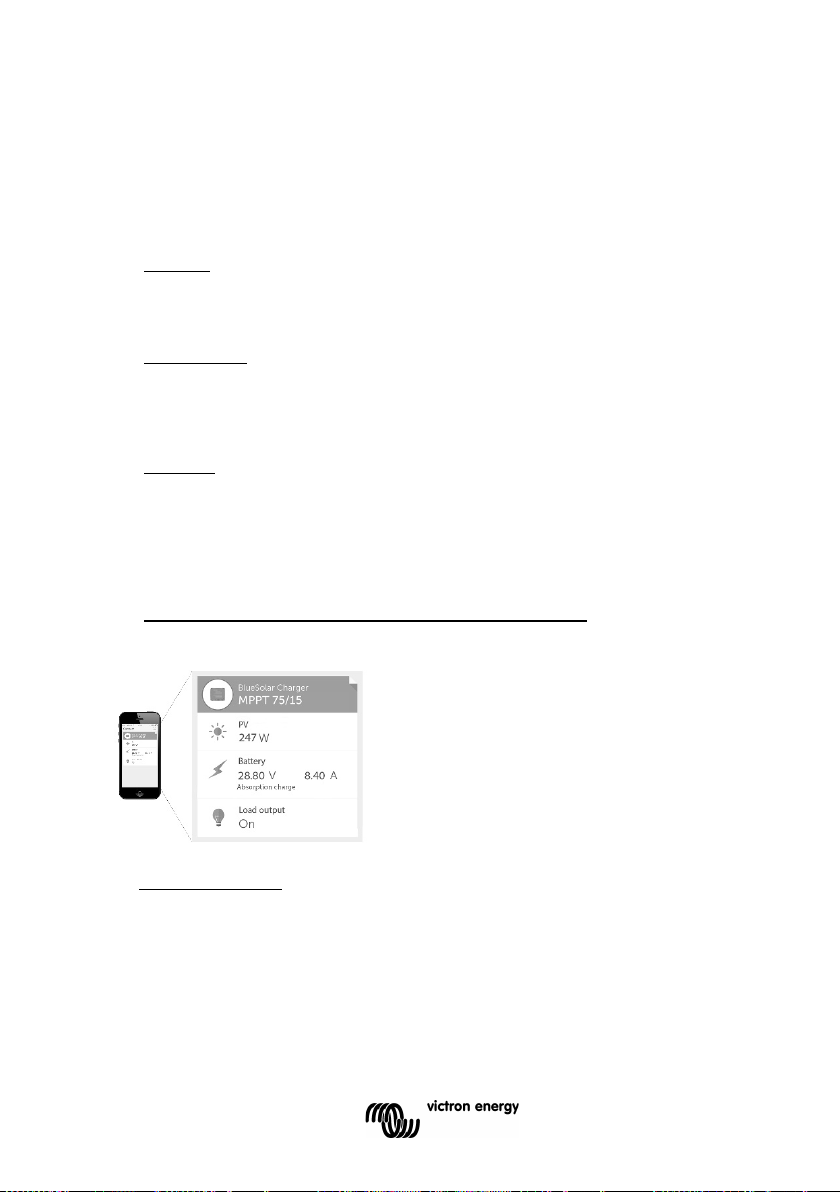
1.7 Real-time data display options
1.7.1. Apple and Android smartphones, tablets and other devices
VE.Direct to Buetooth Low Energy (BLE) dongle needed: see our website.
1.7.2 ColorControl panel
VE.Direct cable needed.
2
Danger of explosion from sparking
2 Safety instructions
Danger of electric shock
● It is advised to read this manual carefully before the product is installed and put into
use.
● This product is designed and tested in accordance with international standards. The
equipment should be used for the designated application only.
● Install the product in a heatproof environment. Ensure therefore that there are no
chemicals, plastic parts, curtains or other textiles, etc. in the immediate vicinity of the
equipment.
● Ensure that the equipment is used under the correct operating conditions. Never
operate it in a wet environment.
● Never use the product at sites where gas or dust explosions could occur.
● Ensure that there is always sufficient free space around the product for ventilation.
● Refer to the specifications provided by the manufacturer of the battery to ensure that
the battery is suitable for use with this product. The battery manufacturer's safety
instructions should always be observed.
● Protect the solar modules from incident light during installation, e.g. cover them.
● Never touch uninsulated cable ends.
● Use only insulated tools.
● Connections must always be made in the sequence described in section 3.5.
● The installer of the product must provide a means for cable strain relief to prevent the
transmission of stress to the connections.
● In addition to this manual, the system operation or service manual must include a battery
maintance manual applicable to the type of batteries used.
EN NL FR DE ES SE Appendix
3

3. Installation
3.1. General
● Mount vertically on a non-flammable substrate, with the power terminals facing
downwards.
● Mount close to the battery, but never directly above the battery (in order to prevent
damage due to gassing of the battery).
● Use cables with 6 mm² cross section. Do not exceed 5 m cable length.
(if the cables to the PV panels must be longer than 5 m, increase cross section or use
parallel cables and install a junction box next to the controller and connect with a short 6
mm² cable to the controller).
● 20A battery fuse: replacable fuse in the controller, next to the battery terminals.
● Grounding: if grounding is required, use one grounding point only. Never ground both
the minus of the solar array and the minus of the battery.
3.2. PV configuration
● The controller will operate only if the PV voltage exceeds battery voltage (Vbat).
● PV voltage must exceed Vbat + 5V for the controller to start. Thereafter minimum PV
voltage is Vbat + 1V.
● Maximum open circuit PV voltage: 75V.
The controller can be used with any PV configuration that satisfies the three above
mentioned conditions.
For example:
12V battery and mono- or polycristalline panels
● Minimum number of cells in series: 36 (12V panel).
● Recommended number of cells for highest controller efficiency: 72
(2x 12V panel in series or 1x 24V panel).
● Maximum: 108 cells (3x 12V panel in series).
24V battery and mono- or polycristalline panels
● Minimum number of cells in series: 72
(2x 12V panel in series or 1x 24V panel).
● Maximum: 108 cells (3x 12V panel in series).
4

3.3. Configuration of the controller (see figure 1 and 2 at the end of the manual))
A four pin header is available to select one of three battery management options:
3.3.1. No jumper: BatteryLife algorithm (see 1.2.2.)
3.3.2. Jumper between pi n 1 and pin 2: conventional (see 1.2.1.)
Low voltage load disconnect: 11,1V or 22,2V
Automatic load reconnect: 13,1V or 26,2V
3.3.3. Jumper between pin 2 and pin 3: conventional (see 1.2.1.)
Low voltage load disconnect: 11,8V or 23,6V
Automatic load reconnect: 14V or 28V
3.4 LED’s
Green LED: will be on or blinking when the battery has been connected
On: one of the two conventional algorithms
Blinking: BatteryLife algorithm
Yellow LED: signals charge sequence
Off: no power from PV array (or PV array connected with reverse polarity)
Blinking fast: bulk charge (battery in partially charged state)
Blinking slow: absorption charge (battery charged to 80% or more)
On: float charge (battery fully charged)
3.5 Cable connection sequence (see figure 3)
First: connect the cables to the load, but ensure that all loads are switched off.
Second: connect the battery (this will allow the controller to recognize system voltage).
Third: connect the solar array (when connected with reverse polarity, the controller will heat
up but will not charge the the battery).
The system is now ready for use.
3.6 Connecting an inverter
The load output can be used to supply DC loads and simultaneously to control an inverter.
The Victron inverters model Phoenix 12/800, 24/800, 12/1200 and 24/1200 can be
controlled by connecting the right side connection of the inverter remote control directly to
the solar charger load output (see figure 4 at the end of this manual).
The bridge between left and right must be removed.
For the Victron inverters model Phoenix 12/180, 24/180, 12/350, 24/350, the Phoenix
Inverter C models and the MultiPlus C models an interface cable is needed: the Inverting
remote on-off cable, article number ASS030550100, see figure 5 at the end of this manual.
EN NL FR DE ES SE Appendix
5
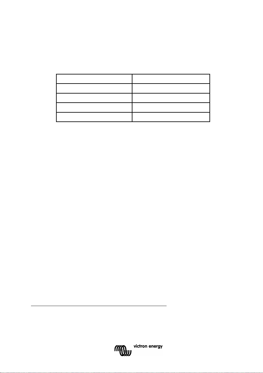
3.7 Battery charging information
The charge controller starts a new charge cycle every moring, when the sun starts shining.
The maximum duration of the absorption period is determined by the battery voltage
measured just before the solar charger starts up in the morning:
Battery voltage Vb (@start-up) Maximum absorption time
Vb < 23,8V 6 h
23,8V < Vb < 24,4V 4 h
24,4V < Vb < 25,2V 2 h
Vb > 25,2V 1 h
If the absorption period is interrupted due to a cloud or due to a power hungry load, the
absorption process will resume when absorption voltage is reached again later on the day,
until the absorption period has been completed.
The absorption period also ends when the output current of the solar charger drops to less
than 1 Amp, not because of low solar array output but because the battery is fully charged
(tail current cut off).
This algorithm prevents over charge of the battery due to daily absorption charging when
the system operates without load or with a small load.
3.7.1. Automatic equalization
Automatic equalization is default set to “OFF”. By using the configuration tool mpptprefs
this setting can be configured with a number between 1 (every day) and 250 (once every
250 days). When automatic equalization is active, the absorption charge will be followed by
a voltage limited constant current period. The current is limited to 8% of the bulk current for
the factory default battery type, and to 25% of the bulk current for a user defined battery
type. The bulk current is the rated charger current unless a lower maximum current setting
has been chosen.
When using the factory default battery type, automatic equalization ends when the voltage
limit 16.2V / 32.4V has been reached, or after t = (absorption time)/8, whichever comes first.
For the user defined battery type automatic equalization ends after t = (absorption time)/2.
When automatic equalisation is not completely finished within one day, it will not resume the
next day, the next equalisation session will take place as determined by the day interval.
3.8 VE.Direct communication port
Several parameters can be customized (VE.Direct to USB cable, ASS030530000, and a
computer needed). See the data communication white paper on our website.
The required software can be downloaded from
http://www.victronenergy.nl/support-and-downloads/software/
The charge controller can be connected the to a Color Control panel, BPP000300100R, with
a VE.Direct to VE.Direct cable.
(divide voltages by 2 for a 12 V system)
6
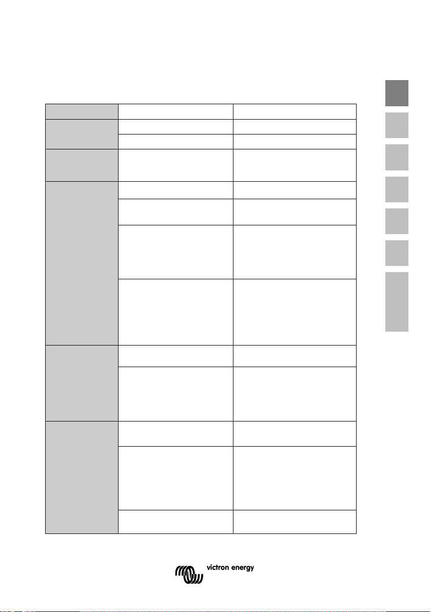
Problem
Possible cause
Solution
Charger does
Reversed PV connection
Connect PV correctly
No fuse inserted
Insert 20A fuse
Reversed battery
A bad battery connection
Check battery connection
Use cables with larger cross
Large ambient temperature
A battery cell is defect
Replace battery
Large ambient temperature
Maximum current limit
Make sure that the output
Disconnect DC load during
Short-circuit
Check for short-circuit in the
4. Troubleshooting
not function
Blown fuse
The battery is
not fully charged
The battery is
being
overcharged
connection
Cable losses too high
difference between charger
and battery (T
T
ambient_batt
Only for a 24V system:
wrong system voltage
chosen (12V instead of 24V)
by the charge controller
difference between charger
and battery (T
T
ambient_batt
)
)
ambient_chrg
ambient_chrg
>
<
EN NL FR DE ES SE Appendix
1. Connect battery correctly
2. Replace fuse
section
Make sure that ambient
conditions are equal for
charger and battery
Disconnect PV and battery,
after making sure that the
battery voltage is at least
>19V, reconnect properly
Make sure that ambient
conditions are equal for
charger and battery
Load output
does not
become active
exceeded
DC load in combination with
capacitive load (e.g.
inverter) applied
current does not exceed 15A
start-up of the capacitive load
Disconnect AC load from the
inverter, or connect inverter as
explained in section 3.6
load connection
7

5 Specifications
Battery voltage
12/24 V Auto Select
Maximum battery current
10 A
15 A
Maximum PV power, 12V 1a,b)
200 W (MPPT range 15 V to 70 V)
Maximum PV power, 24V 1a,b)
400 W (MPPT range 30 V to 70 V)
Automatic load disconnect
Yes, maximum load 15 A
Maximum PV open circuit voltage
75 V
Peak efficiency
98 %
Self consumption
10 mA
Charge voltage 'absorption'
14,4 V / 28,8 V
Charge voltage 'equalization'
16,2 V / 32,4 V
Charge voltage 'float'
13,8 V / 27,6 V
Charge algorithm
multi-stage adaptive
Temperature compensation
-16 mV / °C resp. -32 mV / °C
Continuous/peak load current
15 A / 50 A
11,1 V / 22,2 V or 11,8 V / 23,6 V
or BatteryLife algorithm
13,1 V / 26,2 V or 14 V / 28 V
or BatteryLife algorithm
Battery reverse polarity (fuse)
Output short circuit / Over temperature
Operating temperature
-30 to +60°C (full rated output up to 40°C)
Humidity
100 %, non-condensing
Maximum altitude
2000m
Environmental condition
Indoor, unconditioned
Pollution degree
PD3
VE.Direct
See the data communication white paper on our website
ENCLOSURE
Colour
Blue (RAL 5012)
Power terminals
6 mm² / AWG10
IP43 (electronic components)
IP22 (connection area)
Weight
0,5 kg
Dimensions (h x w x d)
100 x 113 x 40 mm
STANDARDS
Safety
EN/IEC 62109
1a) If more PV power is connected, the controller will limit input power to
Thereafter minimum PV voltage is Vbat + 1V.
BlueSolar charge controller MPPT 75/10 MPPT 75/15
(adjustable)
(adjustable)
(adjustable)
Low voltage load disconnect
Low voltage load reconnect
Protection
Data communication port
Protection category
200W resp. 400W.
1b) PV voltage must exceed Vbat + 5V for the controller to start.
8

1 Algemene beschrijving
1.1 Ultrasnelle MPPT tracking
Vooral als het bewolkt is en de lichtintensiteit voortdurend verandert, verbetert een snel
MPPT algoritme de energieopbrengst tot 30% in vergelijking met PWM-laadcontrollers
en tot 10% in vergelijking met tragere MPPT-controllers.
1.2 BatteryLife: intelligent accubeheer
1.2.1. Conventioneel accubeheer
Wanneer een solar laadcontroller de accu niet in één dag weer in topconditie kan laden,
is het resultaat vaak dat de accu voortdurend schommelt tussen "gedeeltelijk geladen"
en "volledig ontladen". Deze werkwijze (de accu niet regelmatig volledig weer laden)
maakt een loodzuuraccu in een kwestie van weken of maanden helemaal kapot.
1.2.2. BatteryLife algoritme
Het BatteryLife algoritme bewaakt de laadstatus van de accu en verhoogt dag na dag
het niveau voor belastingsontkoppeling tot de absorptiespanning wordt bereikt. Vanaf
dat ogenblik wordt het niveau voor belastingsontkoppeling gemoduleerd zodat de
absorptiespanning ongeveer één keer per week wordt bereikt. Het BatteryLife algoritme
verhoogt de levensduur van de accu aanzienlijk in vergelijking met 1.2.1.
1.2.3. Uitbreiding van het PV systeem of "beperking" van de belasting
Een loodzuuraccu gaat nog langer mee als deze minstens één keer per week volledig
wordt geladen, met inbegrip van verscheidene uren absorptietijd.
1.3 Belastingsuitgang
De belastingsuitgang is beveiligd tegen kortsluiting en kan belastingen met een grote
condensatorgenerator met DC-ingang, zoals een omvormer, voeden (maar geen DCbelasting en een omvormer gelijktijdig starten).
1.4 Interne temperatuursensor
Compenseert absorptie- en float-laadspanningen voor temperat uur.
EN NL FR DE ES SE Appendix
1
1.5 Automatische herkenning van de accuspanning
De laadcontroller past zich automatisch aan aan een systeem van 12V of 24V.
1.6 Driestaps laden
De laadcontroller is geconfigureerd voor een driestaps laadproces: Bulk – Absorptie - Float.
1.6.1. Bulk-fase
Tijdens deze fase voorziet de controller zo veel mogelijk laadstroom om de accu's snel te
laden. Wanneer de accuspanning de instelling van de absorptiespanning bereikt, activeert
de controller de volgende fase (absorptie).
1.6.2. Absorptie-fase
Tijdens deze fase schakelt de controller over op de constante-spanningsmodus, waarbij de
absorptiespanning wordt toegepast op de accu. Wanneer de laadstroom afneemt tot aan de
instelling van de float-leemtegrensstroom, is de accu volledig geladen en schakelt de
controller over naar de float-fase.
1.6.3. Float-fase
Tijdens deze fase wordt de float-spanning toegepast op de accu om deze volledig geladen
te houden.
Wanneer de accuspanning minstens 1 minuut onder 13,2 volt daalt, wordt een nieuwe
laadcyclus geactiveerd.
1.7 Opties voor weergave real time-gegevens
1.7.1. Apple- en Android-smartphones, -tablets en overige apparaten
'VE.Direct to Buetooth Low Energy (BLE)'-dongle vereist: zie onze website.
1.7.2 ColorControl-paneel
VE.Direct-kabel vereist.
2
Ontploffingsgevaar wegens vonken
2 Veiligheidsvoorschriften
Gevaar van elektrische schokken
● Aanbevolen wordt deze handleiding zorgvuldig te lezen voordat het produc t wordt
geïnstalleerd en in gebruik genomen.
● Dit product is ontworpen en getest in overeenstemming met internationale normen.
De apparatuur mag enkel worden gebruikt voor de bedoelde toepassing.
● Installeer het product in een hittebestendige omgevi ng. Zorg ervoor dat er zich geen
chemische stoffen, plastic onderdelen, gordijnen of andere soorten textiel enz. in de
onmiddellijke omgeving van de apparatuur bevinden.
● Zorg ervoor dat de apparatuur wordt gebruikt in de juiste omgevingsvoorwaarden.
Gebruik het product nooit in een vochtige omgeving.
● Gebruik het product nooit op plaatsen waar zich gas- of stofexplosies kunnen
voordoen.
● Zorg ervoor dat er altijd voldoende vrije ruimte rondom het product is voor ventilatie.
●Raadpleeg de specificaties van de accufabrikant om te waarborgen dat de accu
geschikt is voor gebruik met dit product. Volg steeds de veiligheidsvoorschriften van de
accufabrikant.
● Bescherm de zonne-energiemodules tegen rechtstreekse lichtinval tijdens de
installatie, bv. door ze te bedekken.
● Raak nooit niet geïsoleerde kabeluiteinden aan.
● Gebruik enkel geïsoleerd gereedschap.
● Maak de verbindingen steeds in de volgorde zoals beschreven in punt 3.5.
● Degene die het product installeert moet zorgen voor een t rekontlasting voor de
accukabels, zodat een eventuele spanning niet op de kabels wordt overgedragen.
● Naast deze handleiding moet de bedieningshandleiding of de onderhoudshandleiding een
onderhoudshandleiding voor de accu bevatten die van toepassing is op de gebruikte
accutypen.
EN NL FR DE ES SE Appendix
3

3. Installatie
3.1. Algemeen
● Installeer verticaal op een onbrandbaar oppervlak met de voedingsklemmen naar omlaag.
● Installeer dicht bij de accu maar nooit rechtstreeks boven de accu (om schade wegens
gasvorming van de accu te voorkomen).
● Gebruik kabels met een diameter van 6 mm². De maximum lengte van de kabels bedraagt
5 m.
(als de kabels naar de PV panelen langer moeten zijn dan 5 m, gebruik dan kabels met een
grotere doorsnede of parallelle kabels en installeer een kabelkast naast de controller en
verbindt met een korte kabel van 6 mm² met de controller).
● 20A accuzekering: vervangbare zekering in de controller, naast de accuklemmen.
● Aarding: indien aarding nodig is, gebruik dan slechts één aardpunt. Aard nooit zowel
de negatieve pool van de solar installatie als de negatieve pool van de accu.
3.2. PV configuratie
● De controller werkt enkel als de PV spanning hoger is dan de accuspanning (Vaccu).
● De controller start pas als de PV spanning hoger is dan Vaccu + 5V. Vanaf dan bedraagt
de minimum PV spanning Vaccu + 1V
● Maximum PV open klemspanning: 75V.
De controller kan voor eender welke PV configuratie worden gebruikt die voldoet aan de
drie bovenstaande voorwaarden.
Bijvoorbeeld:
12V accu en mono- of polykristallijne panelen
● Minimum aantal seriële cellen: 36 (12V paneel).
● Aanbevolen aantal cellen voor hoogste controllerefficiëntie: 72
(2x 12V paneel in serie of 1x 24V paneel).
● Maximum: 108 cellen (3x 12V paneel in serie).
24V accu en mono- of polykristallijne panelen
● Minimum aantal seriële cellen: 72
(2x 12V paneel in serie of 1x 24V paneel).
● Maximum: 108 cellen (3x 12V paneel in serie).
3.3. Configuratie van de controller (zie afbeelding 1 en 2 achter in het manual)
Er is een vierpins verdeelstuk beschikbaar om een van de drie accubeheeropties te kiezen:
3.3.1. Geen brug: BatteryLife algoritme (zie 1.2.2.)
3.3.2. Brug tussen pin 1 en pin 2: conventioneel (zie 1.2.1.)
Belastingsontkoppeling bij lage spanning: 11,1V of 22,2V
Automatische belastingsherkoppeling: 13,1V of 26,2V
3.3.3. Brug tussen pin 2 en pin 3: conventioneel (zie 1.2.1.)
Belastingsontkoppeling bij lage spanning: 11,8V of 23,6V
Automatische belastingsherkoppeling: 14V of 28V
4

3.4 LED’s
Groene LED: aan of knipperend wanneer de accu is aangesloten
Aan: een van de twee conventionele algoritm en
Knipperend: BatteryLife algoritme
Gele LED: geeft laadsequentie aan
Uit: geen stroom van PV installatie (of PV installatie omgepoold aangesloten)
Snel knipperend: bulk laden (accu gedeeltelijk geladen)
Traag knipperend: absorptieladen (accu tot 80% of meer geladen)
Aan: float-laden (acc u volledig geladen)
3.5 Kabelaansluitingsvolgorde (zie afbeelding 3)
Ten eerste: sluit de kabels aan op de belasting maar zorg ervoor dat alle belastingen
zijn uitgeschakeld.
Ten tweede: sluit de accu aan (hierdoor kan de controller de systeemspanning
herkennen).
Ten derde: sluit het zonnepaneel aan (in het geval van omgepoolde aansluiting warmt
de controller op maar wordt de accu niet geladen).
Het systeem is nu klaar voor gebruik.
3.6 Een omvormer aansluiten
De belastingsuitgang kan worden gebruikt om DC-belastingen te voeden en gelijktijdig
een omvormer te bedienen.
De omvormermodellen Phoenix 12/800, 24/800, 12/1200 en 24/1200 van Victron kunnen
worden bediend door de rechter aansluiting van de afstandsbediening van de omvormer
rechtstreeks op de belastingsuitgang van de zonnelader aan te sluiten (zie afbeelding 4 aan
het eind van deze handleiding).
EN NL FR DE ES SE Appendix
De brug tussen links en rechts moet worden verwijderd.
Voor de Victron-omvormermodellen Phoenix 12/180, 24/180, 12/350, 24/350, de Phoenix Comvormermodellen en de MultiPlus C-modellen is een interfacekabel nodig: de inverting
remote on-off cable, artikelnummer ASS030550100, zie afbeelding 5 aan het einde van
deze handleiding.
5

3.7 Accu-oplaadinformatie
Accuspanning Vb (bij het
opstarten)
De laadcontroller begint elke ochtend, zodra de zon begint te schijnen, een nieuwe
laadcyclus.
De maximale duur van de absorptieperiode wordt bepaald door de accuspanning. Deze
wordt net vóór het opstarten van de acculader in de ochtend gemeten:
Maximale absorptietijd
Vb < 23,8V 6 u
23,8V < Vb < 24,4V 4 u
24,4V < Vb < 25,2V 2 u
Vb > 25,2V 1 u
(deel de spanningen bij een 12 V-systeem door 2)
Als de absorptieperiode wordt onderbroken door een wolk of een stroomvretende last, wordt
het absorptieproces weer hervat als de absorptiespanning later die dag weer wordt bereikt,
tot de absorptieperiode is voltooid.
De absorptieperiode eindigt ook als de uitgangsstroom van de acculader onder minder dan
1 Ampère daalt. Niet vanwege het lage vermogen van het zonnepaneel, maar omdat de
accu volledig wordt opgeladen (staartstroomuitschakeling).
Dit algoritme voorkomt dat de accu als gevolg van dagelijkse absorptielading wordt
overladen als het systeem zonder last of met een kleine last wordt gebruikt.
3.7.1. Automatische egalisatie
De automatische egalisatie staat standaard ingesteld op "OFF" (uit). Door gebruik te
maken van het configuratietool mpptprefs kan deze instelling worden geconfigureerd met
een getal tussen 1 (elke dag) en 250 (om de 250 dagen). Als de automatische egalisatie
actief is, wordt de absorptietijd gevolgd door een periode van constante stroom met
beperkte spanning. De stroom wordt beperkt tot 8% van de bulkstroom voor alle standaard
fabrieksaccu's en tot 25% van de bulkstroom voor een gebruikersgedefinieerd accutype. De
bulkstroom is de nominale laderstroom, tenzij u voor een lagere maximum stroominstelling
hebt gekozen.
In het geval van standaard fabrieksaccu's stopt de automatische egalisatie als de
spanningslimiet 16,2 V / 32,4 V wordt bereikt of nadat t = (absorptietijd)/8, naargelang wat
zich het eerst voordoet.
Bij het gebruikersgedefinieerde accutype stopt de automatische egalisatie na
t = (absorptietijd)/2.
Als de automatische egalisatie niet volledig is voltooid binnen één dag, wordt deze niet de
volgende dag hervat. De volgende egalisatiesessie vindt dan plaats, zoals bepaald door de
daginterval.
6

3.8 VE.Direct-communicatiepoort
Meerdere parameters kunnen worden aangepast (VE.Direct naar USB-kabel,
ASS030530000, en een computer zijn nodig). Zie het witboek over datacommunicatie
op onze website.
De vereiste software kan worden gedownload van
http://www.victronenergy.nl/support-and-downloads/software/
De laadcontroller kan worden aangesloten op een Color Control-paneel,
BPP000300100R, met een VE.Direct naar VE.Direct-kabel.
EN NL FR DE ES SE Appendix
7

4. Probleemoplossing
Probleem
Mogelijke oorzaak
Oplossing
Omgepoolde PV aansluiting
Sluit PV juist aan
Geen zekering geplaatst
Plaats een 20A zekering
Zekering doorgebra nd
Omgepoolde accuaa nsluiting
Gebrekkige accuverbinding
Controleer accuverbinding
Te hoge kabelverliezen
Gebruik kabels met een grotere
Zorg ervoor dat de
Koppel de PV install ati e en de
Er is een accucel defect
Vervang accu
Zorg ervoor dat de
Zorg ervoor dat de
Koppel de DC belasting los
Controleer of de
Lader werkt niet
De accu wordt niet
volledig geladen
Groot omgevingstem pe rat uu rverschil
tussen lader en accu (T
)
T
omg_accu
Enkel voor een 24V syst eem: foute
systeemspanning gekozen (12V
i.p.v. 24V) door de laadcontroller
omg_lader
1. Sluit accu juist aan
2. Vervang zekering
diameter
>
omgevingsomstandigheden
gelijkt zijn voor de lader en de
accu
accu los, zorg ervoor dat de
accuspanning minstens >19V
bedraagt en sluit opnieuw aan
De accu wordt
overladen
Belastingsuitgang
wordt niet geactiveerd
8
Groot omgevingstem pe rat uu rverschil
tussen lader en accu (T
)
T
omg_accu
Maximum stroomlimiet overschreden
DC belasting in combinatie met
capacitieve belasting (bv. omvormer)
toegepast
Kortsluiting
omg_lader
<
omgevingsomstandigheden
gelijkt zijn voor de lader en de
accu
uitgangsstroom niet ho ge r is dan
15A
tijdens het opstarten van de
capacitieve belasting. Koppel de
DC belasting los tijdens het
opstarten van de capacitieve
belasting Koppel de ACbelasting los van de omvormer,
of sluit de omvormer aan zoals
beschreven in punt 3.6.
belastingsaansluiting
kortgesloten is

BlueSolar laadcontroller
MPPT 75/10
MPPT 75/15
Accuspanning
12/24 V Auto Select
Maximum ac custroom
10 A
15 A
Maximum PV vermogen, 12V 1a,b)
200 W (MPPT-bereik 15 V tot 70 V)
Maximum PV vermogen, 24V 1a,b)
400 W (MPPT-bereik 30 V tot 70 V)
Automatische belastingsontkoppeling
Ja, maximum belasting 15 A
75 V maximum in koude omgeving
74 V om te starten en wanneer in bedrijf
Laadspanning 'absorptie'
14,4 V / 28,8 V (regelbaar)
Laadspanning 'float'
13,8 V / 27,6 V (regelbaar)
Laadspanning 'egalisatie'
16,2 V / 32,4 V
Laadalgoritme
meertraps adaptief
Temperatuurcompensatie
-16 mV / °C resp. -32 mV / °C
Continue
belastingstroom/piekbelastingstroom
11,1 V / 22,2 V of 11,8V / 23,6V
of BatteryLife algoritme
13,1 V / 26,2 V of 14 V / 28 V
of BatteryLife algoritme
Ompoling accu (zekering)
Overtemperatuur
Bedrijfstemperatuur
-30 tot +60°C (volledig nominaal vermogen tot 40°C)
Vocht
100 %, niet condenserend
Maximale hoogte
2000 m
Omgevingsomstandigheden
Binnen, natuurlijk
Verontreinigingsgraad
PD3
VE.Direct
website
Kleur
Blauw (RAL 5012)
Vermogensklemmen
6 mm² / AWG10
IP43 (elektronische componenten)
IP 22 (aansluitingsgebied)
Gewicht
0,5 kg
Afmetingen (h x b x d)
100 x 113 x 40 mm
NORMEN
Veiligheid
EN/IEC 62109
1a) Als er meer PV vermogen wordt aangesloten, beperkt de con troller het ingangsvermogen tot
Vanaf dan bedraagt de minimum PV spanning Vaccu + 1V
5 Specificaties
Maximum PV open spanning
Piekefficiëntie 98 %
Eigen verbruik 10 mA
15 A / 50 A
Belastingsontkoppeling bij lage span ning
Belastingsherkoppeling bij lage spanning
Beveiliging
Kortsluiting uitgang
EN NL FR DE ES SE Appendix
(regelbaar)
Datacommunicatiepoort
Beschermingsklasse
200W resp. 400W.
1b) De controller start pas als de PV spanning hoger is dan Vaccu + 5V.
Zie het whitepaper over datacommunicatie o p onze
BEHUIZING
9
 Loading...