

Victron Energie MultiPlus-II GX Product Manual
manual-multiplus-ii-gx-24Vand48V-3000and5000-230V
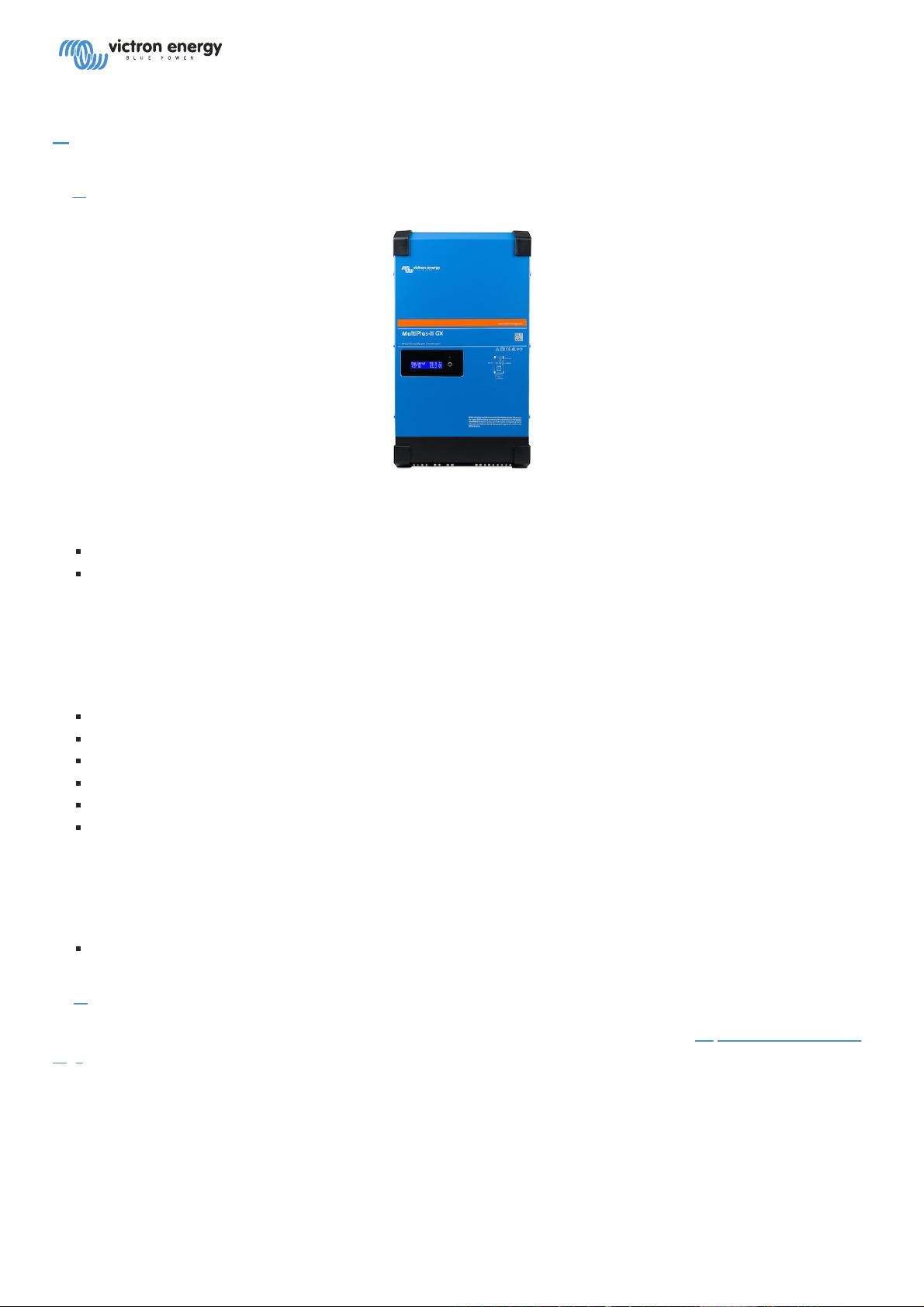
# MultiPlus-II GX - Product Manual
1. # Introduction
The Victron MultiPlus-II GX integrates the following elements:
A powerful MultiPlus-II inverter/charger
A GX card with a 2x16 character display
These elements come prewired, and preconfigured together inside a single unit. This simplifies installation, saving
time and money.
This document explains:
Features
Behaviour
Specifications
Limitations
Installation instructions
Troubleshooting steps
You must read it to understand how to use your product safely and reliably.
This manual applies to:
MultiPlus-II GX 48/3000/35-32
2. # Latest Documentation
You can quickly access the latest version of this manual online by visiting the following link: https://ve3.nl/MultiPlus-
ii-gx
Or scanning this QR code with your phone:
1 / 26

3. # Safety Instructions
Please read the documentation supplied with this product first, so that you are familiar with the safety signs and
directions before using the product. This product is designed and tested in accordance with international standards.
The product should be used for the designated application only.
WARNING
DANGER OF ELECTRICAL SHOCK
The product is used in combination with a permanent energy source (battery). Even if the product is switched off, a
dangerous electrical voltage can occur at the input and/or output terminals. Always switch the AC power off and
disconnect the battery before performing maintenance.
The product contains no internal user-serviceable parts. Do not remove the front panel and do not put the product
into operation unless all panels are fitted. All maintenance should be performed by qualified personnel.
Never use the product at sites where gas or dust explosions could occur. Refer to the specifications provided by the
manufacturer of the battery to ensure that the battery is suitable for use with this product. The battery
manufacturer's safety instructions should always be observed.
This product is not intended for use by persons (including children) with reduced physical, sensory or mental
capabilities, or lack of experience and knowledge, unless they have been given supervision or instruction concerning
use of the product by a person responsible for their safety. Children should be supervised to ensure that they do not
play with the product.
WARNING
Do not lift heavy objects unassisted
3.1. # Installation
Read the installation instructions before commencing installation activities. For electrical work, follow the local
national wiring standard, regulation and this installation instructions.
This product is a safety class I device (supplied with a ground terminal for safety purposes). Its AC input and/or
output terminals must be provided with uninterruptible grounding for safety purposes. An additional grounding
point bonded to the chassis is located on the inside the terminal cover of the product. See Appendix
manual-multiplus-ii-gx-24Vand48V-3000and5000-230V
2 / 26

manual-multiplus-ii-gx-24Vand48V-3000and5000-230V
The ground conductor should be at least 4mm². If it can be assumed that the grounding protection is damaged, the
product should be taken out of operation and prevented from accidentally being put into operation again; contact
qualified maintenance personnel.
Ensure that the connection cables are provided with fuses and circuit breakers. Never replace a protective device by
a component of a different type. Refer to the connection of battery cables section of the manual for the correct part.
Do not invert neutral and phase when connecting the AC.
Check before switching the device on whether the available voltage source conforms to the configuration settings of
the product as described in the manual.
Ensure that the equipment is used under the correct operating conditions. Never operate it in a wet or dusty
environment.
Ensure that there is always sufficient free space around the product for ventilation, and that ventilation openings are
not blocked.
Install the product in a heatproof environment. Ensure therefore that there are no chemicals, plastic parts, curtains
or other textiles, etc. in the immediate vicinity of the equipment.
This inverter is provided with an internal isolation transformer providing reinforced insulation.
3.2. # Transport and storage
On storage or transport of the product, ensure that the mains supply and battery leads are disconnected.
No liability can be accepted for damage in transit if the equipment is not transported in its original packaging.
Store the product in a dry environment; the storage temperature should range from –20°C to 60°C.
Refer to the battery manufacturer's manual for information on transport, storage, charging, recharging and disposal
of the battery.
4. # Product Description
The basis of the MultiPlus-II is an extremely powerful sine inverter, battery charger and transfer switch in a compact
casing. It is suited for use in Marine, Automotive, as well as stationary land-based applications.
4.1. # Features applying to all applications
4.1.1. # GX LCD display
A backlit 2 x 16 character display screen shows system parameters.
4.1.2. # CAN-bus Connections
A CAN-bus connection allows connecting of VE.Can products as for example Victron MPPT Solar Chargers, or a
Lynx Shunt VE.Can. Also, it can be configured to connect to CAN-bus BMS batteries.
4.1.3. # Ethernet and Wifi
3 / 26

manual-multiplus-ii-gx-24Vand48V-3000and5000-230V
Ethernet and Wifi connections allow for local and remote system monitoring, as well as connection to Victron's free
VRM portal for long term system performance information.
4.1.4. # Automatic and uninterruptible switching
In the event of a supply failure or when the generating set is switched off, the MultiPlus-II GX will switch over to
inverter operation and take over the supply of the connected devices. This is done so quickly that operation of
computers and other electronic devices is not disturbed (Uninterruptible Power Supply or UPS functionality). This
makes the MultiPlus-II GX highly suitable as an emergency power system in industrial and telecommunication
applications.
4.1.5. # Two AC outputs
Besides the usual uninterruptable output (AC-out-1), an auxiliary output (AC-out-2) is available that disconnects its
load in the event of battery operation. Example: an electric boiler that is allowed to operate only if the genset is
running or shore power is available. There are several applications for AC-out-2.
4.1.6. # Three phase capability
The unit can be connected with others and configured for three-phase output. Up to 6 sets of three can be parallel
connected to provide 45 kW / 54 kVA inverter power and more than 600A charging capacity.
4.1.7. # PowerControl – maximum use of limited AC power
The MultiPlus-II GX can supply a huge charging current. This implies heavy loading of the AC mains or generator.
Therefore a maximum current can be set. The MultiPlus-II GX then takes other power users into account, and only
uses 'surplus' current for charging purposes.
4.1.8. # PowerAssist – Extended use of generator or shore current: the MultiPlus-II GX
This feature takes the principle of PowerControl to a further dimension allowing the MultiPlus-II GX to supplement
the capacity of the alternative source. Where peak power is often required only for a limited period, the MultiPlus-II
GX will make sure that insufficient AC mains or generator power is immediately compensated for by power from the
battery. When the load reduces, the spare power is used to recharge the battery.
4.1.9. # Programmable
All settings can be changed with a PC and free of charge software, downloadable from our website
www.victronenergy.com. See this manual for more information - https://docs.victronenergy.com/veconfigure.html
4.1.10. # Programmable relay
The MultiPlus is equipped with a programmable relay. The relay can be programmed for different applications, for
example as a starter relay for a generator.
4.1.11. # External current transformer (optional)
External current transformer option to implement PowerControl and PowerAssist with external current sensing.
4.1.12. # Programmable analog/digital input/output ports (Aux in 1 and Aux in 2, see appendix)
The MultiPlus is equipped with 2 analog/digital input/output ports.
These ports can be used for several purposes. One application is communication with the BMS of a lithium-ion
battery.
4 / 26

manual-multiplus-ii-gx-24Vand48V-3000and5000-230V
4.2. # Features specific On-grid and off-grid systems combined with PV
4.2.1. # External current transformer (optional)
When used in a grid-parallel topology the internal current transformer cannot measure the current to or from the
mains. In this case an external current transformer has to be used. See appendix A.
4.2.2. # Frequency shift
When solar inverters are connected to the output of a MultiPlus-II GX, excess solar energy is used to recharge the
batteries. Once the absorption voltage is reached, charge current will reduce and excess energy will be fed back into
the mains. If the mains is not available, the MultiPlus-II GX will slightly increase the AC frequency to reduce the
output of the solar inverter.
4.2.3. # Built-in Battery Monitor
The ideal solution when the MultiPlus-II GX is part of a hybrid system (diesel generator, inverter/chargers, storage
battery, and alternative energy). The built-in battery monitor can be set to start and stop the generator:
Start at a preset % discharge level, and/or
start (with a preset delay) at a preset battery voltage, and/or
start (with a preset delay) at a preset load level.
Stop at a preset battery voltage, or
stop (with a preset delay) after the bulk charge phase has been completed, and/or
stop (with a preset delay) at a preset load level.
4.2.4. # Autonomous operation when the grid fails
Houses or buildings with solar panels or a combined micro-scale heating and power plant or other sustainable
energy sources have a potential autonomous energy supply which can be used for powering essential equipment
(central heating pumps, refrigerators, deep freeze units, Internet connections, etc.) during a power failure. A problem
is however that grid connected sustainable energy sources drop out as soon as the grid fails. With a MultiPlus-II GX
and batteries, this problem can be solved: the MultiPlus-II GX can replace the grid during a power failure. When the
sustainable energy sources produce more power than needed, the MultiPlus-II GX will use the surplus to charge the
batteries; in the event of a shortfall, the MultiPlus-II GX will supply additional power from the battery.
4.3. # Battery charger
4.3.1. # Lead-acid batteries
Adaptive 4-stage charge algorithm: bulk – absorption – float – storage
The microprocessor-driven adaptive battery management system can be adjusted for various types of batteries. The
adaptive function automatically adapts the charging process to battery use.
The right amount of charge: variable absorption time
In the event of slight battery discharge, absorption is kept short to prevent overcharging and excessive gas
formation. After deep discharging, the absorption time is automatically extended in order to fully charge the battery.
Preventing damage due to excessive gassing: the BatterySafe mode
5 / 26

manual-multiplus-ii-gx-24Vand48V-3000and5000-230V
If, in order to quickly charge a battery, a high charge current in combination with a high absorption voltage has
been chosen, damage due to excessive gassing will be prevented by automatically limiting the rate of voltage
increase once the gassing voltage has been reached.
Less maintenance and aging when the battery is not in use: the Storage mode
The Storage mode kicks in whenever the battery has not been subjected to discharge during 24 hours. In the
Storage mode float voltage is reduced to 2,2V/cell (13,2V for 12V battery) to minimise gassing and corrosion of the
positive plates. Once a week the voltage is raised back to the absorption level to 'equalize' the battery. This feature
prevents stratification of the electrolyte and sulphation, a major cause of early battery failure.
Battery voltage sense: the correct charge voltage
Voltage loss due to cable resistance can be compensated by using the voltage sense facility to measure voltage
directly on the DC bus or on the battery terminals.
Battery voltage and temperature compensation
The temperature sensor (supplied with the product) serves to reduce charging voltage when battery temperature
rises. This is particularly important for maintenance-free batteries, which could otherwise dry out by overcharging.
4.3.2. # Li-ion batteries
Victron LiFePO4 Smart batteries
Use the VE.Bus BMS
4.3.3. # Other Li-ion batteries
Please see https://www.victronenergy.com/live/battery_compatibility:start
4.3.4. # More on batteries and battery charging
Our book 'Energy Unlimited' offers further information on batteries and battery charging, and is available free of
charge on our website: www.victronenergy.com/support-and-downloads/whitepapers
For more information on adaptive charging, please also refer to the General Technical Information on our website.
4.4. # ESS – Energy Storage Systems: feeding energy back into the grid
When the MultiPlus-II GX is used in a configuration in which it will feed back energy into the grid it is required to
enable grid code compliance by selecting the appropriate grid code country setting with the VEConfigure tool.
Once set, a password will be required to disable grid code compliance or change grid code related parameters.
If the local grid code is not supported by the MultiPlus-II GX an external certified interface device should be used to
connect the MultiPlus-II GX to the grid.
The MultiPlus-II GX can also be used as a bidirectional inverter operating parallel to the grid, integrated into a
customer designed system (PLC or other) that takes care of the control-loop and grid measurement,
Special note regarding NRS-097 (South Africa)
1. The maximum allowed impedance of the network is 0.28Ω + j0.18Ω
6 / 26

manual-multiplus-ii-gx-24Vand48V-3000and5000-230V
2. The inverter is fulfilling the unbalance requirement in case of multiple single phase units only when the Color
Control GX is part of the installation.
Special notes regarding AS 4777.2 (Australia/New Zealand)
1. Certification and CEC approval for off-grid use does NOT imply approval for grid-interactive installations.
Additional certification to IEC 62109.2 and AS 4777.2.2015 are required before grid-interactive systems can be
implemented. Please check the Clean Energy Council website for current approvals.
2. DRM – Demand Response Mode When the AS4777.2 grid code has been selected in VEconfigure, DRM 0
functionality is available on port AUX1 (see appendix A. To enable grid connection, a resistance of between
5kOhm and 16kOhm must be present between the terminals of port AUX1 (marked + and - ). The MultiPlus-II
GX will disconnect from the grid in case of an open circuit or a short circuit between the terminals of port
AUX1. The maximum voltage that may be present between the terminals of port AUX1 is 5V. Alternatively, if DRM
0 is not required, this functionality can be disabled with VEConfigure.
5. # Operation
5.1. # On/Off/Charger Only Switch
The switch is located on the underside to the bottom right of the MultiPlus-II GX.
The swich has three positions. The centre position 0 is Off. The I position is On, and the II position is Charger Only.
When switched to 'I / On' (rocked towards the back of the unit), the product will come into operation and the
inverter is fully functional.
If an AC voltage is connected to the 'AC in' terminal, it will be switched through to the 'AC out' terminal, if within
specifications. The inverter will switch off, and the charger commences charging. 'Bulk', 'absorption' or 'float' will
display, depending on the charger mode.
If the voltage at the 'AC-in' terminal is rejected, the inverter will switch on.
When the switch is switched to 'II / charger only', only the battery charger of the Multi will operate (if mains voltage is
present). In this mode input voltage also is switched through to the 'AC out' terminal.
NOTE: When only the charger function is required, ensure that the switch is switched to 'II / charger only'. This
prevents the inverter from being switched on if the mains voltage is lost, thus preventing your batteries from running
flat.
6. # GX LCD Interface
The display screen will present useful information about your system.
6.1. # On/off behaviour
When the MultiPlus-II GX is switched off with the physical switch on the device or with the Remote on/off terminals,
then the GX card is off as well. If you switch the MultiPlus-II GX remotely, using a Digital Multi Control, then the GX
card will be remain powered. Also when switching the inverter/charger off from within the GX menus, the GX card
will remain powered.
7 / 26

manual-multiplus-ii-gx-24Vand48V-3000and5000-230V
Lastly, when the inverter/charger switches itself off due to an alarm, such as low battery or overtemperature, then the
GX Card will remained powered and functional as well.
6.2. # Push button behaviour
When the GX Card is on, pushing the button beside the screen will activate the backlight. The backlight will turn
itself off after 5 minutes.
Once the backlight has been activated, pushing the button again will cycle through the available display options.
Some options will be displayed automatically, and other require a button push to display.
6.3. # Information displayed
Solar Power, Voltage and Charge state (if connected)
ESS/DVCC reason codes (if active)
Solar Daily Yield
Inverter/charger charge state (eg Bulk, ESS)
Battery State of Charge, Power and Voltage
Network IP Address and Connection Type (if connected).
AC input and output Power
In a system with more than one phase, there will be additional AC input and output information available, eg
Phase 1 AC input Voltage and Power.
Phase 1 AC output Voltage and Power.
Phase 2 AC input Voltage and Power.
Phase 2 AC output Voltage and Power.
Phase 3 AC input Voltage and Power.
Phase 3 AC output Voltage and Power.
6.4. # Error Code Display
If there is an error with the system, the error code will be displayed on the screen. The screen will display VE.Bus
error code numbers, and MPPT error codes (if connected).
Basic information about the VE.Bus Error codes are in the Error Indications section.
For further details about the error codes please see:
VE.Bus Error Codes
MPPT Error Codes
The error will display until it is cleared.
7. # Installation
8 / 26
 Loading...