

Victron Energie BlueSolar PWM-Pro, SCC010005010, SCC010010010, SCC010020110, SCC010030010 Series Manual
BlueSolar
PWM
-
Pro
Charge C
ontroller
Manual
IMPORTANT
• Always connect the battery first, in order to allow
the Controller to recognize system voltage
• Use a 12V (36 cells) solar array for a 12V system.
• Use a 24V (72 cells) solar array for a 24V system.
EN
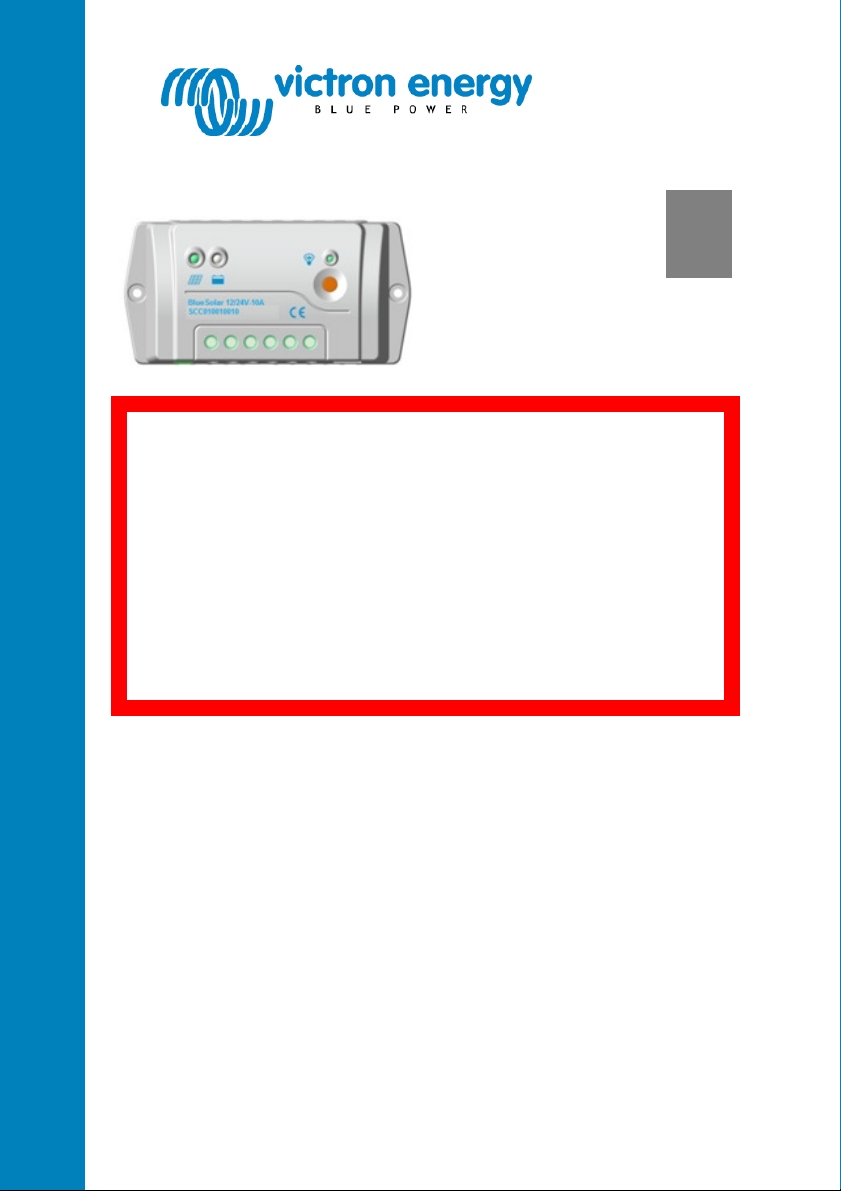
12V | 24V - 5A SCC010005010
12V | 24V - 10A SCC010010010
12V | 24V - 20A SCC010020110
12V | 24V - 30A SCC010030010


1. General Safety Information
Read all instructions and cautions in the manual before starting the
installation.
Keep the controller away from rain exposure, severe dust, vibration,
corrosive gas and intense electromagnetic interference.
Do not allow water to enter the controller.
There are no user serviceable parts inside the controller. Do not
disassemble or attempt to repair it.
2. Features
• Integrated battery monitor function (optional remote panel
needed to display state of charge).
• Fully programmable lighting control (programming tools: Remote
Panel or free of charge PC software).
• Three stage battery charging (bulk, absorption, float), fully
programmable with the Remote Panel.
• Load output with low voltage disconnect and manual control
(default setting).
• Optional external temperature sensor.
• Load output protected against over load and short circuit.
• Protected against reverse polarity connection of the solar panels
and/or battery.
1
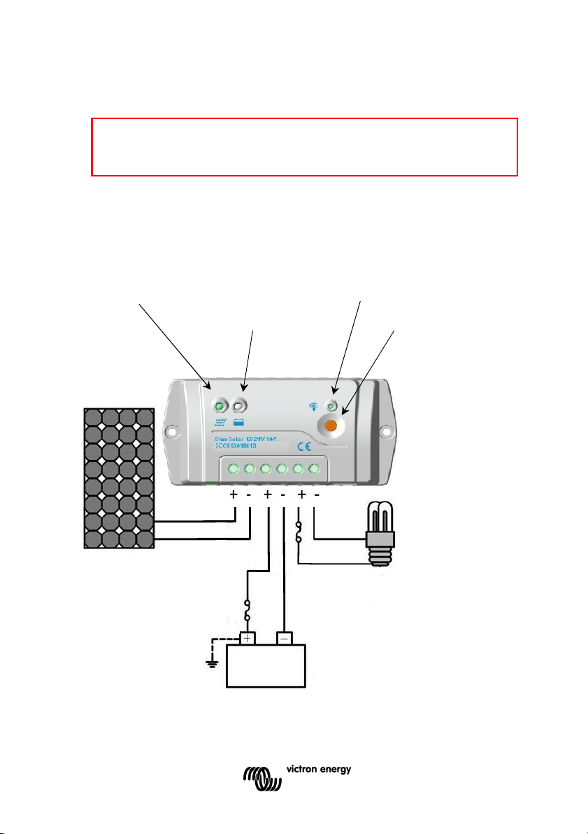
3. Intallation and operation
Important no
te: a
lways connect the battery
first, in order
to allow the controller to recognize system voltage.
- The controller is a common positive controller.
- If system grounding is required, preferably the positive pole of the battery
should be grounded.
- Use one system ground only.
Charging Status LED indicator Load Status LED indicator
Battery Status LED indicator Switch Button
2
 Loading...