

Page 1
ENGLISH
Victron VM-3P75CT Energy
Meter Manual
This manual is also available in HTML5.
Rev 02 - 01/2024
Page 2

Victron VM-3P75CT Energy Meter Manual
Table of Contents
1. Safety Instructions ................................................................................................................... 1
2. Introduction ........................................................................................................................... 2
2.1. Features ...................................................................................................................... 2
2.2. What's in the box? ........................................................................................................... 3
3. Installation ............................................................................................................................. 4
3.1. AC wiring ..................................................................................................................... 4
3.2. AC wiring diagrams ......................................................................................................... 5
3.3. Ethernet and VE.Can wiring ................................................................................................ 6
4. Configuration & Monitoring ........................................................................................................ 7
4.1. LED codes .................................................................................................................. 10
5. Firmware Updates .................................................................................................................. 11
6. Restart and reset to factory defaults ........................................................................................... 12
7. Troubleshooting .................................................................................................................... 13
7.1. The LED alternates between green and red blinking (bootloader mode) ........................................... 13
7.2. Error codes ................................................................................................................. 13
7.3. FAQ ......................................................................................................................... 13
7.3.1. The current value seems abnormally high for the displayed power ....................................... 13
7.3.2. The firmware update via the Ethernet connection failed .................................................... 13
8. Technical data ...................................................................................................................... 14
8.1. Technical specifications ................................................................................................... 14
8.2. Enclosure dimensions .................................................................................................... 15
Page 3
Victron VM-3P75CT Energy Meter Manual
1. Safety Instructions
General
Please read the safety instructions below before installing and using the VM-3P75CT energy meter to avoid risks of fire, electric
shocks, personal injuries or equipment damage.
This product is designed and tested in accordance with international standards. The equipment should be used for its designated
application only and in accordance with the specified operating parameters.
Installation
Installation, maintenance, service and adjustments must be made by qualified personnel only. To
reduce the risk of electric shock, do not perform any service other than that specified in the operating
instructions unless you are qualified.
• For electrical work, follow the local national wiring standards, regulations and these installation instructions. Connection to the
mains supply must be in accordance with the national regulations for electrical installations.
• Never install near fire sources, explosive materials, combustibles or other flammable sources. Never use it at places where gas
or other chemical explosions could occur.
• A switch or circuit breaker must be included in the installation. It must be suitably located for easy accessibility and clearly
labelled as the designated disconnecting device for the VM-3P75CT.
• Turn off mains power before installing or performing operations on it.
• Do not put fingers or insert objects or sharp metallic objects into the terminals.
• Install it in a dry environment.
• Do not apply strong force on the equipment to prevent crashes and deterioration.
• It is not allowed to use the current clamps on bare wires.
• Make sure the ground connection is properly done to prevent equipment damage.
Operation, service and maintenance
• Do not use the device if it shows any signs of damage or does not function properly.
• Do not use the VM-3P75CT if it is broken, defective, cracked, damaged, or malfunctioning.
• The VM-3P75CT contains no serviceable parts.
• If a current transformer is defective, it must be replaced by qualified personnel.
• Regular maintenance of the VM-3P75CT is not required.
• Avoid moisture, oil/soot/vapours, and keep the device clean.
• Clean using a dry cloth on the front side of the VM-3P75CT.
Page 1 Safety Instructions
Page 4

Victron VM-3P75CT Energy Meter Manual
2. Introduction
The Victron VM-3P75CT energy meter is a standard device to measure the power and energy of single- and three-phase
applications and calculates each phase's power values and broadcasts this over VE.Can or Ethernet with a high rate.
It has built-in Ethernet and VE.Can ports for connecting to a GX device and the split-core current transformers enable easy and
quick installation without modifying existing wiring.
The energy meter works out of the box (the firmware may need to be updated; details can be found in the Firmware
Updates [11] chapter) as a grid meter for systems with a MultiPlus and Quattro. Configuration (via VictronConnect) is only
required for changing the role and manual IP configuration rather than the default DHCP.
Its data is displayed on a GX device such as the Cerbo GX or Ekrano GX , as well as in VictronConnect and our VRM Portal.
2.1. Features
• Capable of measuring up to 80Arms per phase (but rated at 75A)
• Modbus/UDP communication over Ethernet
• Split-core current transformers for easy installation without modifying the existing wiring
• Uses vector registration method (the vectors of each phase L1, L2 and L3 are summed)
The VM-3P75CT can be configured for four different roles in a GX device, such as the Cerbo GX or the Ekrano GX:
1. As a Grid meter and used as control input for an Energy Storage System (ESS)
2. To measure the output of a PV Inverter
3. To measure the output of an AC Genset
4. As an AC meter to measure a dedicated AC load circuit
It offers two options for connecting to a GX device:
1. A wired ethernet connection to a local network via its built-in Ethernet port so the GX device can reach it.
2. A wired VE.Can connection via the onboard VE.Can port directly to the GX device.
Page 2 Introduction
Page 5
Victron VM-3P75CT Energy Meter Manual
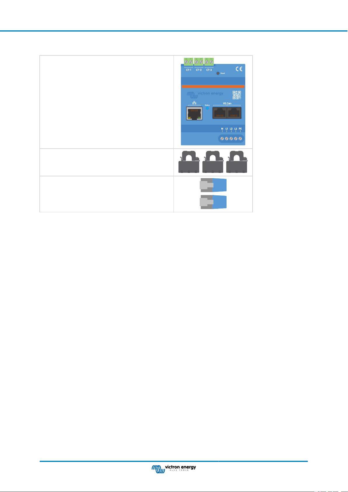
2.2. What's in the box?
Victron VM-3P75CT with 3 input terminal blocks
3x Split-core current transformer, wired ready for connection
Wire length: 640mm (25.3in)
VE.Can terminators (2 pcs)
Page 3 Introduction
Page 6

Victron VM-3P75CT Energy Meter Manual
3. Installation
3.1. AC wiring
Note the following when installing:
• It is not allowed to use the current clamps on bare wires.
• As the current transformers are quite delicate, the following procedure should be followed when installing the current
transformers:
1. First, open Section A. Be careful not to twist the head.
The head part of the product will naturally lift off.
2. Clamp the head part by hand.
3. Make sure the current transformers are connected to the correct phase wire and input terminal. The transformers are
marked with an indicator showing which input port they belong to. The devices are calibrated at the factory, and accuracy
will decrease if the current transformers are not matched to the correct input.
4. There is an arrow printed on the CT labelled L ← K. Ensure the arrow points towards loads.
AC Loads
5. Make sure the correct wires are connected to the voltage terminals. The device could be damaged if two phase wires are
connected to the neutral and L1 input.
6. In order to isolate the energy meter from power for service or maintenance, a switch or a 2-pole circuit breaker (L1 + N)
is required. In addition, a fuse (500mA) is required in the neutral conductor. This can be omitted if the circuit breaker fuse
rating is 500mA.
Extending the wires of the split-core current transformers
The wires of the current transformers can be extended if necessary, but note that this will increase the measurement noise
slightly.
In general: The longer the cables, the higher the ground floor noise. However, if the length is doubled, the additional error is still
low (almost 0A).
To minimise induced noise, it is recommended to twist the wires like the wires supplied with the device.
AC source
Should a split-core transformer become damaged, you can order a replacement from your Victron dealer or
via this link. Please note that the device is no longer calibrated if the current transformer is replaced.
Page 4 Installation
Page 7
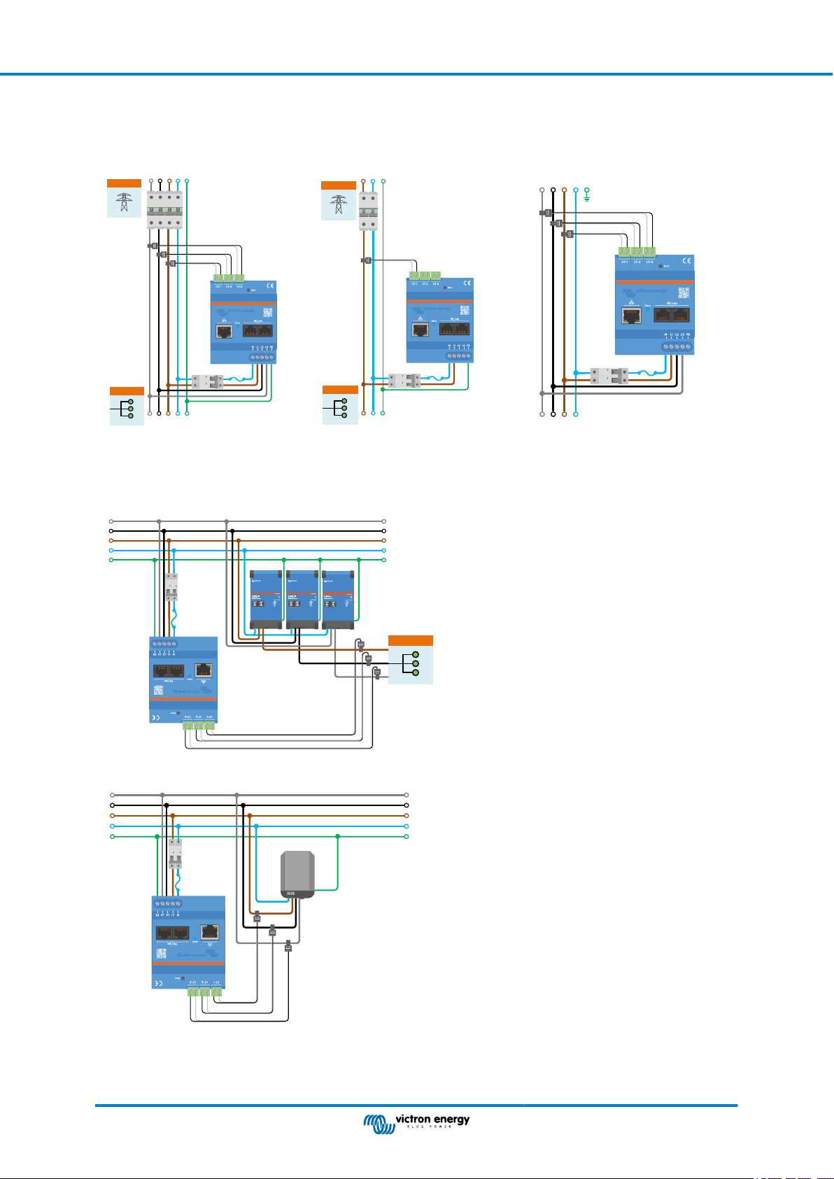
3.2. AC wiring diagrams
General AC wiring examples
PE
N
Grid
AC loads
L1L2L3
VM-3P75CT
Switch or circuit
breaker
Fuse 500mA
Victron VM-3P75CT Energy Meter Manual
PE
N
L1
Grid
VM-3P75CT
Switch or circuit
Fuse 500mA
breaker
AC loads
PE
N
L1L2L3
VM-3P75CT
Switch or circuit
breaker
Fuse 500mA
PE
N
L1L2L3
VM-3P75CT 3-phase wiring when
used as a grid meter
VM-3P75CT 1-phase wiring when
used as a grid meter
PE
N
L1
Specific AC wiring examples depending on application and role
L3
L2
L1
N
PE
Switch or circuit
breaker
Fuse 500mA
VM-3P75CT
L3
L2
L1
N
PE
AC-out of Inverter/
Charger
VM-3P75CT 3 Phase Wiring - Role is set to measure AC loads
L3
L2
L1
N
PE
Switch or circuit
breaker
L3
L2
L1
N
PE
N
L1L2L3
VM-3P75CT 3-phase IT system wiring
Fuse 500mA
3P PV Inverter or Genset
VM-3P75CT
VM-3P75CT 3 Phase Wiring - Role is set to measure a PV Inverter (or Generator)
Page 5 Installation
Page 8

Victron VM-3P75CT Energy Meter Manual
3.3. Ethernet and VE.Can wiring
The VM-3P75CT can be connected to the GX device either via VE.Can or Ethernet.
Suppose there is a local network with an Ethernet connection (via a router) to which the GX device is connected via Ethernet or
WiFi. In that case, connecting the energy meter to the same network via Ethernet is reasonable.
Alternatively, you can connect the energy meter directly to the GX device via its VE.Can connectors. Ensure that the VE.Can
network is properly terminated at both ends with the supplied VE.Can terminators.
For both applications, use a good quality Ethernet cable such as the Victron RJ45 UTP Cable, which can also be purchased from
your Victron dealer in different lengths.
The VM-3P75CT connected to the GX device via Ethernet
The VM-3P75CT connected to the GX device via VE.Can
Page 6 Installation
Page 9

Victron VM-3P75CT Energy Meter Manual
4. Configuration & Monitoring
The VM-3P75CT is configured through VictronConnect.
• When using the VE.Can connection, the VM-3P75CT will be automatically detected once connected to the VE.Can port and
properly terminated.
• When using the Ethernet connection, the VM-3P75CT is automatically recognised by the GX device.
VictronConnect configuration and monitoring
There are two options to connect to the VM-3P75CT using VictronConnect from a mobile device, laptop or PC:
1. Direct via Ethernet using the Modbus/UDP connection in the local network
2. Or by using VictronConnect-Remote (VC-R) remotely via either VE.Can or Modbus/UDP (requires the GX device connected
to the VRM Portal)
The VM-3P75CT supports Instant Readout of key data (total power and power per phase) at a glance directly from the Device list
(1) in VictronConnect. This works via a local network connection and VictronConnect-Remote (VC-R).
The data display in VictronConnect is divided into a Status page (2) for status messages of the individual phases and an Energy
page (3) with the overview of the fed-in and purchased energy per phase.
1
Tapping on the cog wheel in the top right corner of the Status- or Energy page will take you to the Settings page, from where the
network settings and the configuration of the meter are made.
The Settings menu (4) includes the following options:
• Role: (8) Set this to Grid meter, PV inverter, Generator or AC load, depending on which appliances you want to measure.
• Phase Configuration: (7) If the VM-3P75CT is installed single-phase, set it to Only L1. For a 3-phase installation, set it to
3-phase.
2
3
• IP Configuration: (5) We recommend leaving this setting on Automatic (DHCP). Manual configuration (6) is only necessary in
very rare cases. Contact your network administrator for the details.
Page 7 Configuration & Monitoring
Page 10

Victron VM-3P75CT Energy Meter Manual
5 7 8 9
Once the Role has been properly set, the configuration is done.
GX device monitoring
After the VM-3P75CT has established a connection to the GX device in the local network, the device must be activated in the
Modbus TCP/UDP menu so that it appears in the Device List.
Go to Settings → Modbus TCP/UDP devices → Discovered devices and enable the discovered energy meter; it's disabled by
default when first installed and turned on.
After activation, the energy meter will be displayed in the Device List.
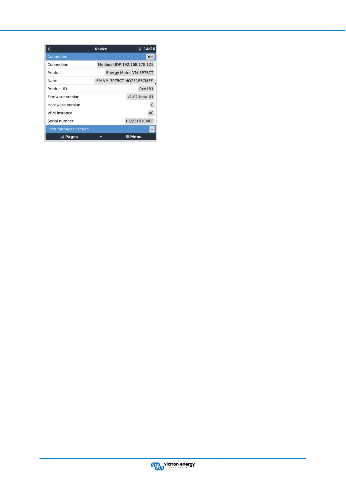
Right-click on the device will take you to the device overview page on which the current data of the individual phases, the AC
totals and the total energy per phase can be read out.
An overview of the connection and hardware-specific data can be found on the Device page. There, you can also assign a
custom name for the meter.
Page 8 Configuration & Monitoring
Page 11
Victron VM-3P75CT Energy Meter Manual
Page 9 Configuration & Monitoring
Page 12

Victron VM-3P75CT Energy Meter Manual
4.1. LED codes
The VM-3P75CT has a built-in LED that shows the status of the energy meter.
The LED states are as follows:
• Blinking fast alternately green/red: Bootloader/update mode.
• Solid green: All ok, normal running mode.
• Blinking green @ 1Hz (50% duty cycle): Identify unit. Stops after 60s.
• Off for 3 seconds, on for another 10 seconds and off again while pressing the reset button for about 15 seconds: Reset
to factory defaults.
• Off and immediately on after pressing the reset button briefly: Restart the device.
• Solid red: The LED will illuminate solid red if there is an error.
Page 10 Configuration & Monitoring
Page 13

Victron VM-3P75CT Energy Meter Manual
5. Firmware Updates
The firmware of the VM-3P75CT can be updated in multiple ways:
• VRM: Remote firmware update: This works over Ethernet and VE.Can connection
• VictronConnect-Remote (VC-R): This works over Ethernet and VE.Can connection
• VictronConnect locally via Ethernet/WiFi connection on the local network
Page 11 Firmware Updates
Page 14

Victron VM-3P75CT Energy Meter Manual
6. Restart and reset to factory defaults
The VM-3P75CT has a recessed RESET button that allows you to reset the energy meter to factory defaults or to restart
the device if a problem occurs without interrupting the power supply. In addition, a factory reset can also be carried out via
VictronConnect.
Restart
To restart the energy meter, briefly press the RESET button. The LED goes off and immediately on again.
Reset to factory defaults
A factory reset resets the following settings to:
• IP configuration: Automatic (DHCP)
• Role: Grid
• Phase configuration: 3-phase
• Custom name: VM-3P75CT plus the serial number
Reset to factory defaults step-by-step using the RESET button:
1. Press and hold the RESET button.
The unit resets and will blank the LED for ~3 seconds. The device then restarts, and the LED lights up green again.
2. Keep pressing the button for another ~10 seconds.
After 10 seconds, the LED will go blank again.
3. Release the button.
The device will restart.
Reset to factory defaults step-by-step using the VictronConnect app:
1. Open the VictronConnect app and tap the energy meter you want to reset in the device list.
2. On the status page, tap the gear icon.
3. On the Settings page that opens, tap the 3 vertical dots at the top right.
4. Tap Reset to defaults on the pop-up menu.
5. In the next pop-up menu, confirm the process by tapping on YES.
After the factory reset, the energy meter must be configured again as outlined in the chapter Configuration & Monitoring [7].
Page 12 Restart and reset to factory defaults
Page 15
Victron VM-3P75CT Energy Meter Manual
7. Troubleshooting
7.1. The LED alternates between green and red blinking (bootloader mode)
There can be two reasons for this behaviour:
1. A firmware update is currently being carried out. Once the firmware update is complete, the energy meter automatically
returns to application mode, indicated by a solid green LED.
2. A firmware update was unsuccessful, or there is no application to start. The energy meter remains in bootloader mode until
the application has been installed through a firmware update.
To fix this, perform the firmware update again as outlined in the Firmware Updates [11] chapter.
When the energy meter is in bootloader mode, the only available methods for performing a firmware
update are through VictronConnect locally (via Ethernet or WiFi) or remotely using VRM: Remote
firmware updates (utilising VE.Can or Ethernet connectivity).
Performing a firmware update via VictronConnect Remote (VC-R) in bootloader mode is impossible.
7.2. Error codes
The VM-3P75CT indicates an error by turning the LED solid red when an error is present. Simultaneously, an error code appears
on the GX device, VRM, and VictronConnect.
The following error codes can be displayed:
• 116 - Calibration data lost
If the unit does not work and error 116 pops up as the active error, the unit is faulty. Contact your dealer for a replacement.
• 119 - Settings corrupt
The energy meter cannot read its configuration and stopped.
To fix the error, perform a factory reset as described in the Restart and reset to factory defaults [12] chapter.
• 122 - kWh counters corrupt
To fix this error, reset the kWh counter.
7.3. FAQ
7.3.1. The current value seems abnormally high for the displayed power
The energy meter calculates each phase's power in Watts (P), and the active (real) power is displayed. Active Power is the
product of the voltage, the current, and the power factor, where the power factor is traditionally denoted by cos(θ). In a system
with unity power factor, that is where cos(θ)=1, the real power will be equal to the apparent power, the product of the RMSvoltage and current.
In most electrical systems there will also be a reactive power, caused by the existence of inductive and/or capacitive loads. In
such systems, the power factor will be less than unity, and the apparent power will always be more than the real power.
In AC systems, it is therefore normal and even expected for the apparent power (S), that is the RMS- voltage multiplied by the
current, to be higher than the real power (P).
Many smaller electronic devices, including USB chargers and LED lighting, can have a particularly poor power factor, which will
lead to a large difference between P and S. This condition is often exacerbated by the installation of renewable energy generation
devices since such devices are legally required to operate at near-unity. The larger renewable generation tends to cancel out all
the good power factor, leaving behind only the poor power factor caused by the loads.
If the power factor is a concern, the solution is to look at power factor correction equipment, or to invest in loads that have better
power factor. Switch mode power supplies for personal computers often have power factor correction built-in already.
7.3.2. The firmware update via the Ethernet connection failed
If you encounter problems updating the VM-3P75CT's firmware via Ethernet, try connecting it to the GX device via VE.Can
(see the Ethernet and VE.Can wiring [6] section for details), perform the update again as outlined in the Firmware Updates [11]
chapter, and then reconnect via Ethernet.
Page 13 Troubleshooting
Page 16
Victron VM-3P75CT Energy Meter Manual
8. Technical data
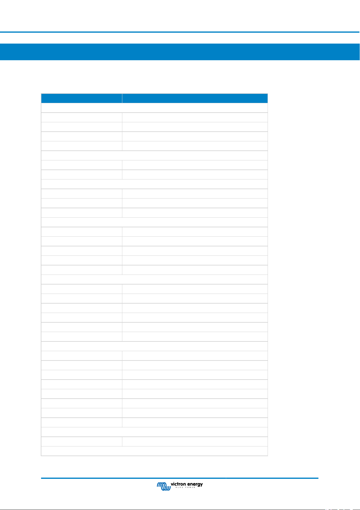
8.1. Technical specifications
VM-3P75CT REL200300100
VOLTAGE INPUTS
Voltage connection Direct
Input voltage range L-N 85 to 265VAC
Input voltage range L-L 150 to 460VAC
Frequency 50/60Hz
CURRENT INPUTS
Current connection Via current transformers (included - wire length 640mm (25.2in)
Rated current 75A
COMMUNICATION
VE.Can communication port Two RJ45 connectors (VE.Can terminators included)
Ethernet communication port One RJ45 connector, Modbus UDP
Refresh rate 100ms
POWER SUPPLY
Type Self-power supply via L1-N
Switch or circuit breaker Required as means of a disconnecting device - not included
External fuse
Consumption 1.45W / 3.1VA
Frequency 50/60Hz
ENCLOSURE
Material & colour Polycarbonate, blue (RAL5012)
Voltage connection Screw terminals 0.25 - 1.5mm2 (24 - 16AWG)
Current transformer connection Pluggable screw terminals (included)
Protection category IP20
Weight 370g (including packaging)
Dimensions 90 x 71 x 59mm (3.5 x 2.8 x 2.3in)
ENVIRONMENTAL
Indoor/outdoor usage Indoor only
Operating temperature From -25 to +55 °C
Storage temperature From -25 to +70 °C
Relative humidity < 90% non-condensing
Altitude 2000m (6562ft)
Mains supply voltage fluctuations ±0.1Vin
Overvoltage category Cat. III
Pollution degree 2
STANDARDS
Safety EN-IEC 61010-1
[1]
Can be omitted if a circuit breaker with a fuse rating of 500mA is used as the isolating device.
[1]
Required in the neutral conductor - 500mA, not included
Page 14 Technical data
Page 17
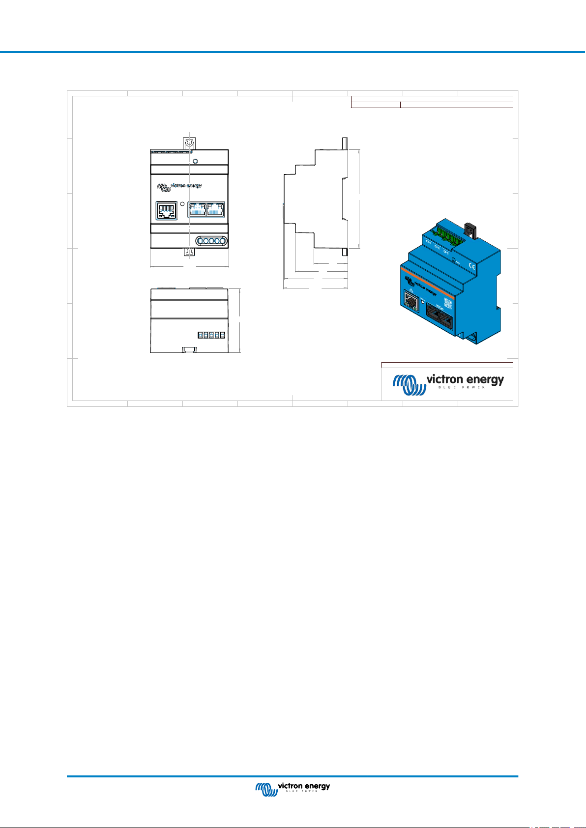
8.2. Enclosure dimensions
71.2
90
31
48
58
58.9
58
Dimension Drawing - VE-EnergyMeter
REL200300100
Energy Meter VM-3P75CT
Dimensions in mm
D
E
F
C
1
2
3
4
B
A
3
2
1
5
C
D
4
6
7
8
A
B
8
7
6
5
F
E
Victron VM-3P75CT Energy Meter Manual
Page 15 Technical data
 Loading...