

Page 1
ENGLISH
VE.Bus BMS V2
Product manual
This manual is also available in HTML5.
Rev 05 - 01/2024
Page 2

VE.Bus BMS V2
Table of Contents
1. General description .................................................................................................................. 1
2. Safety precautions ................................................................................................................... 3
3. Installation ............................................................................................................................. 4
3.1. What's in the box? ........................................................................................................... 4
3.2. Basic installation ............................................................................................................. 5
3.2.1. Minimal VE.Bus firmware ......................................................................................... 5
3.2.2. Battery BMS cable connections ................................................................................. 6
3.2.3. Mains detector ..................................................................................................... 7
3.3. Controlling DC loads and chargers ........................................................................................ 8
3.3.1. DC load control .................................................................................................... 8
3.3.2. DC charge control ................................................................................................. 8
3.3.3. Controlling inverter/chargers, solar chargers and other battery chargers .................................. 8
3.3.4. DVCC operation with VE.Bus BMS V2 ......................................................................... 9
3.3.5. Charger control via Charge disconnect ......................................................................... 9
3.3.6. Charging with an alternator ...................................................................................... 9
3.4. Remote on/off terminal .................................................................................................... 10
3.5. GX device .................................................................................................................. 11
3.6. Connecting a Digital Multi Control or a VE.Bus Smart dongle ....................................................... 12
4. System examples .................................................................................................................. 13
4.1. System with a GX device, on/off switch and pre-alarm circuit ........................................................ 13
4.2. System with a SmartShunt, BatteryProtect and solar charger ....................................................... 14
4.3. Basic system ............................................................................................................... 15
4.4. System with an alternator ................................................................................................ 16
4.5. Three-phase system with a Digital Multi Control ....................................................................... 17
5. Operation ............................................................................................................................ 18
5.1. Important warning ......................................................................................................... 18
5.2. LED indications ............................................................................................................ 18
6. Updating the firmware ............................................................................................................. 19
6.1. Updating the firmware using VRM: Remote firmware update ........................................................ 19
6.2. Updating the firmware using VictronConnect .......................................................................... 20
7. Frequently asked questions ...................................................................................................... 21
8. Technical specifications VE.Bus BMS V2 ..................................................................................... 22
9. Appendix ............................................................................................................................. 23
9.1. Dimensions VE.Bus BMS V2 ............................................................................................ 23
9.2. VE.Bus BMS V2 compared to VE.Bus BMS V1 ....................................................................... 24
Page 3

VE.Bus BMS V2
1. General description
The VE.Bus BMS V2 is a battery management system (BMS) for Victron Energy Lithium Battery Smart batteries available with a
nominal voltage of 12.8V or 25.6V in various capacities. This is the safest of the mainstream lithium battery types. They can be
connected in series, parallel and series/parallel so that a battery bank can be built for system voltages of 12V, 24V or 48V. Up
to four 12.8V batteries or two 25.6V batteries can be connected in series. A total of 20 batteries can be connected, resulting in
energy storage of up to 84kWh in a 12V system or up to 102kWh in a 24V and 48V system.
Protects each individual cell of a Victron Lithium Battery Smart (LiFePO₄) battery
Each individual cell of a LiFePO₄ battery must be protected against under- and overvoltage, as well as low and high temperature.
This is exactly what the VE.Bus BMS V2 does in combination with the battery's BTV module, which provides appropriate signals
to the BMS.
The Victron Lithium Battery 12.8V & 25.6V Smart have integrated Balancing, Temperature and Voltage control (acronym: BTV)
and connect to the VE.Bus BMS V2 with two M8 circular connector cord sets. The BTVs of several batteries can be daisy
chained. Please see our Lithium Battery Smart product page for details.
Depending on the signals from the battery, the BMS will:
• Generate a pre-alarm signal to warn of an imminent cell undervoltage.
• Shut down or disconnect loads in case of cell undervoltage.
• Turn off the inverter of VE.Bus inverter/chargers in case of cell undervoltage.
• Reduce the charge current in case of cell overvoltage or overtemperature of VE.Bus inverter/chargers or VE.Bus inverters.
• Shut down or disconnect battery chargers in case of cell overvoltage or overtemperature.
Pre-alarm
The pre-alarm output is normally free floating and becomes high in case of imminent cell undervoltage. It is set by default at 3.1V
per cell and is adjustable on the battery between 2.85V and 3.15V per cell. The minimum delay between pre-alarm and load
disconnect is 30 seconds. Note that the pre-alarm does not generate a notification on the GX device and therefore not on VRM
either.
Load disconnect
The Load disconnect output is normally high and becomes free floating in case of cell undervoltage. The Load disconnect output
can be used to control:
• The remote on/off terminal of a load.
• The remote on/off terminal of an electronic load switch like a BatteryProtect (preferred low power consumption solution).
Charge disconnect
The Charge disconnect output is normally high and becomes free floating in case of cell over voltage or over temperature. The
Charge disconnect output can be used to control:
• The remote on/off terminal of a charger, like an AC charger, DC-DC charger or solar charger.
• A Cyrix-Li-Charge relay.
• A Cyrix-Li-ct Battery Combiner.
LED indicators
The BMS has the following LED indications:
•
Status LED (blue): Lights once every 10 seconds when the Multi is switched on to indicate BMS info frames are being sent.
When the Multi is off, either due to a low cell/remote off or just switched off by means off the front panel switch, the BMS goes
into low power mode but continues to send BMS info frames (with a slightly longer interval between them). In this mode the
BMS status led does not light up to conserve energy. If the BMS is stuck in the bootloader, the status LED will flash rapidly. This
can happen, for example, after an interrupted firmware update (to fix this, restart the update on VictronConnect or via VRM).
• Cell voltage above 4V LED (red): Lights when the Charge disconnect output is low because of cell overvoltage or
overtemperature.
Page 1 General description
Page 4

VE.Bus BMS V2
• Cell voltage above 2.8V LED (blue): Lights when the Load disconnect output is high and the battery cell voltages are above
2.8V.
Connectivity and communication with GX device
• On/off/charger-only control of VE.Bus products via a GX device.
• GX DVCC control of solar chargers. There is no need to install an BatteryProtect or Cyrix-Li-Charge to control solar chargers
via the BMS like the VE.Bus BMS V1 does.
Has separate power input and output connections for GX devices
• The GX-Pow output supplies GX power from either the battery or from the Aux-In input, whichever voltage is higher.
• An AC-DC adapter (not included) or other power supply connected to the Aux-In input will ensure that the GX device is
powered as long as that Aux power is available, even if the battery is low, for example, due to an error the battery is in under
voltage and the inverter/charger is switched off. This allows the system to be diagnosed remotely (assuming the Internet is still
available), even when (almost) everything else is turned off. See the Technical specifications [22] for the required power rating
of an AC-DC adapter.
True remote on/off terminal
• The VE.Bus BMS V2 needs to remain connected to the battery positive in order to be able to keep the Multi in low power mode
even when AC input on the Multi is available (Multi will stop inverting/charging, close the transfer switch and indicate a low
battery error on the status LEDs). In comparison, disconnecting the battery positive of the VE.Bus BMS V1 only really turns the
Multi off when no AC input is available.
Page 2 General description
Page 5

2. Safety precautions
• Installation must strictly follow the national safety regulations in compliance with the enclosure, installation,
creepage, clearance, casualty, markings and segregation requirements of the end-use application.
• Installation must be performed by qualified and trained installers only.
• Carefully study the product manuals of all connected devices before installing them.
• Switch off the system and check for hazardous voltages before altering any connection.
• Do not open the lithium battery.
• Do not discharge a new lithium battery before it has been fully charged first.
• Charge a lithium battery only within the specified limits.
• Do not mount the lithium battery upside down or on its sides.
• Check if the lithium battery has been damaged during transport.
VE.Bus BMS V2
Page 3 Safety precautions
Page 6

VE.Bus BMS V2
3. Installation
3.1. What's in the box?
The following items are in the box:
• 1x VE.Bus BMS V2
• 1x Mains detector
• 1x 0.3m RJ45 UTP cable
• Piece of Velcro adhesive hook and loop tape
Note that the DC power cable to power the BMS is not included. Use any 1-wire cable with at least 0.75mm2 (AWG 16) and a 1A
inline fuse.
What's in the box
Page 4 Installation
Page 7

VE.Bus BMS V2
3.2. Basic installation
1. Connect the battery BMS cables to the BMS. For multiple batteries, see the Battery BMS cable connections [6] chapter. Be
sure to read and follow the installation instructions in the Lithium Battery Smart manual.
2. Connect the inverter/charger or inverter positive and negative cables to the battery. Make sure it has been updated to the
most recent firmware version. For more information, see the Minimal VE.Bus firmware [5] chapter.
3. Connect the battery positive via the red power cable with the fuse to the BMS "Battery+" terminal.
4. Connect the VE.Bus port of the Inverter/charger or inverter to the "MultiPlus/Quattro" port of the BMS using the included
RJ45 cable.
5. In case of a new style MultiPlus 12/1600/70, new style MultiPlus 12/2000/80, MultiPlus-II or Quattro-II, don't install the mains
detector. For more information, see the Mains detector [7] chapter.
Basic BMS connections
Note that the BMS does not have a battery negative connection. This is because the BMS obtains battery
negative from the VE.Bus. As such, the BMS cannot be used without a VE.Bus Inverter/charger or a VE.Bus
inverter.
3.2.1. Minimal VE.Bus firmware
Before connecting the BMS to the system, the VE.Bus firmware of all inverter/chargers or inverters used in the system needs to
be updated to the latest firmware version (version xxxx489 or above).
If the inverter/charger firmware is between version xxxx415 and xxxx489, the "VE.Bus BMS" or "ESS" assistant must be installed
in the inverter/charger.
If the inverter/chargers or inverters have a VE.Bus firmware version below xxxx415, the BMS will generate a VE.Bus error 15
(VE.Bus combination error). This error indicates that the VE.Bus products or firmware versions cannot be combined. If it is not
possible to update the inverter/chargers or inverters to a VE.Bus firmware version xxxx415 or higher the VE.Bus BMS V2 cannot
be used.
Page 5 Installation
Page 8

VE.Bus BMS V2
3.2.2. Battery BMS cable connections
In the case of several batteries in parallel and/or series configuration, the BMS cables should be connected in series (daisychained), and the first and last BMS cable should be connected to the BMS.
If the BMS cables are too short, they can be extended with extension cables, the M8 circular connector Male/Female 3 pole
cables.
Left: Connecting a single battery. Right: connecting multiple batteries.
Page 6 Installation
Page 9
VE.Bus BMS V2
3.2.3. Mains detector
The mains detector is not required for the new style MultiPlus 12/1600/70 and MultiPlus 12/2000/80,
MultiPlus-II, Quattro-II and inverter models. In this case, these chapters can be skipped, and the mains
detector should be disposed of.
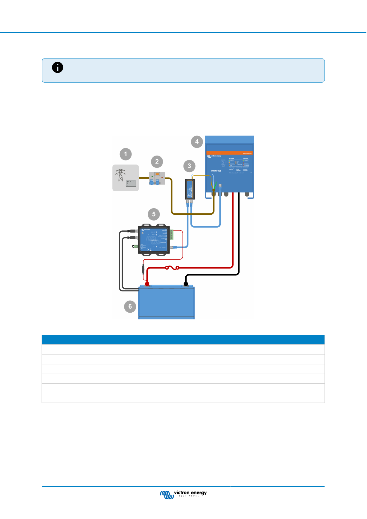
The purpose of the mains detector is to restart the inverter/charger when the AC supply becomes available in case the BMS has
shut down the inverter/charger due to low cell voltage (so that it can recharge the battery).
In systems consisting of several units configured for parallel, three-phase, or split-phase operation, the mains detector should be
wired in the master or leader unit only.
In the case of a MultiPlus, only use one AC wire pair, and in the case of a Quattro, use both wire pairs.
AC detector wiring example.
# Description
1 AC grid or generator
2 AC circuit breaker and RCD
3 Mains detector
4 Inverter/charger
5 VE.Bus BMS V2
6 Lithium Battery Smart
Page 7 Installation
Page 10

VE.Bus BMS V2
3.3. Controlling DC loads and chargers
3.3.1. DC load control
DC loads with remote on/off terminals:
DC loads must be switched off or disconnected to prevent cell undervoltage. The Load disconnect output of the BMS can be used
for this purpose. The Load disconnect output is normally high (= battery voltage). It becomes free-floating (= open circuit) in case
of an impending cell undervoltage (no internal pull down to limit residual current consumption in case of low cell voltage).
DC loads with a remote on/off terminal that switches the load on when the terminal is pulled high (to battery plus) and switches it
off when the terminal is left free-floating, can be controlled directly with the BMS Load disconnect output.
DC loads with a remote on/off terminal that switches the load on when the terminal is pulled low (to battery minus) and switches
it off when the terminal is left free-floating, can be controlled with the BMS Load disconnect output via an Inverting remote on/off
cable.
Note: please check the residual current of the load when in the off state. After low cell voltage shutdown, a
capacity reserve of approximately 1Ah per 100Ah battery capacity is left in the battery. For example, a residual
current of 10mA can already damage a 200Ah battery if the system is left in a discharged state for more than
eight days.
Disconnecting a DC load via a BatteryProtect:
Use a BatteryProtect for DC loads that do not have a remote on/off terminal or for switching groups of DC loads off.
A BatteryProtect will disconnect the DC load when:
• Its input voltage (= battery voltage) has decreased below a preset value.
• Its remote on/off H terminal becomes free floating (usually high). This signal is provided by the Load disconnect output
(wired to the remote on/off H terminal of the BatteryProtect) of the VE.Bus BMS V2. See the wiring example System with a
BatteryProtect and a solar charger [14].
3.3.2. DC charge control
3.3.3. Controlling inverter/chargers, solar chargers and other battery chargers
In the event of high cell voltage or low temperature, battery charging must be stopped to protect the battery cells. Depending
on the system, chargers are either controlled via DVCC or must be controlled via their remote on/off terminals and the Charge
disconnect output of the VE.Bus BMS V2.
• In systems with a GX device, you must enable DVCC to ensure that the solar chargers and other DVCC-compatible devices
only charge when they should. See DVCC operation with VE.Bus BMS V2 [9] for details.
• In systems without a GX device, the BMS Charge disconnect output must control the solar charger and other chargers, either
via remote on/off, a BatteryProtect or a Cyrix-Li-Charge. See Charger control via Charge disconnect [9] for details.
Page 8 Installation
Page 11

VE.Bus BMS V2
3.3.4. DVCC operation with VE.Bus BMS V2
DVCC (Distributed Voltage and Current Control) allows a GX device to control compatible devices such as solar chargers,
Inverter RS, Multi RS or Multis.
In order for the GX device to control the solar chargers, Inverter RS or Multi RS in a system with a VE.Bus BMS V2, DVCC
must be enabled. These chargers are controlled by setting their maximum charge current limit to zero when the VE.Bus BMS V2
requests that charging should stop.
Note that the presence of a VE.Bus BMS V2 does not control the charge voltage of the solar chargers, Inverter RS, Multi RS or a
Multi.
• In an ESS system, the Multi controls the charging voltage of the solar chargers, Inverter RS and Multi RS using the
configuration made with VE.Configure or VictronConnect. In other words: The charge algorythm must be configured in the
Multi.
• In a non-ESS (off-grid) system, the solar chargers, Inverter RS, Multi RS and Multi follow their own internal charge algorithm.
Here, all devices must be set to the appropriate lithium charge algorithm.
AC chargers and smaller Phoenix inverters are not (yet) controlled by the GX device, and therefore you still need to wire signal
wiring (via ATC aka Charge disconnect) to control such devices.
3.3.5. Charger control via Charge disconnect
Chargers that are not DVCC compatible or installed in systems without a GX device can be controlled via the VE.Bus BMS V2
Charge disconnect output, provided the chargers have a remote on/off port.
The Charge disconnect output, normally high (equal to battery voltage), must be connected to the H terminal of the charger's
remote on/off connector. At high cell voltage or low temperature, the Charge disconnect output becomes free-floating and pulls
the charger's remote on/off H terminal low (to battery minus), stopping the charge.
For battery chargers with a remote terminal that activates the charger when the terminal is pulled low (to battery minus) and
deactivates when the terminal is left free floating, the Inverting remote on-off cable can be used.
Alternatively, a Cyrix-Li-Charge relay can be used. The Cyrix-Li-Charge relay is a unidirectional combiner that inserts between
a battery charger and the lithium battery. It will engage only when charge voltage from a battery charger is present on its
charge-side terminal. A control terminal connects to the Charge disconnect output of the BMS.
3.3.6. Charging with an alternator
Alternator charging can be controlled either with a DC-DC charger such as the Orion-Tr Smart, or with a SolidSwitch 104 when
controlling an external alternator regulator like the Balmar MC-614.
Both devices are then also controlled by the BMS Charge disconnect output wired to the Orion-Tr Smart or SolidSwitch 104
remote on/off H terminal. See System with an alternator [16]
Page 9 Installation
Page 12

VE.Bus BMS V2
3.4. Remote on/off terminal
The BMS remote on/off terminal can be used to turn the entire system on and off while the BMS remains connected to battery
positive, which keeps the inverter in low power (discharging and charging not allowed) mode even if it is still connected to AC In.
The remote H and L terminals switch the system on when:
• Contact is made between the remote H terminal and L terminal, for example, via the wire bridge or a switch.
• Contact is made between the remote connector H terminal and battery positive.
• Contact is made between the remote connector L terminal and battery negative.
A typical application is switching off the system when a predetermined state of charge (SoC) is reached in a BMV. Its relay then
operates the remote on/off terminal of the BMS. Note that at least the wire loop between pins L and H must be plugged in, so that
the VE.Bus BMS V2 can switch on.
Page 10 Installation
Page 13

VE.Bus BMS V2
3.5. GX device
For solar chargers, Inverter RS, Multi RS or Multis to be controlled by the BMS via a GX device, the following requirements
should be met:
• The GX device Venus OS firmware must be version 2.80 or above.
Installation:
1. Connect the GX device VE.Bus port to the Remote panel port on the BMS via an RJ45 cable (not included). Note that this is
different from the former VE.Bus BMS V1, which allowed only the connection of a Digital Multi Control. The VE.Bus BMS V2
allows to connect a GX device, a VE.Bus Smart dongle or a Digital Multi Control.
2. Connect the GX device "power +" terminal to the GX-Pow terminal of the BMS and connect the GX device "power -" terminal
to the negative terminal of the battery.
3. Connect the positive wire of an (optional) AC-DC power supply to the AUX-in terminal of the BMS and connect the negative
wire to the negative battery terminal. Note that the AC-DC power supply is optional and most likely not needed in off-grid
installations such as boats or RVs.
4. Perform a VE.Bus re-detect system action on the GX device. This action is available in the inverter/charger menu on the GX
device.
GX device connections
The functionality of the GX-Pow and Aux-In terminals:
• The GX-Pow output supplies GX power from either the battery or from the Aux-In input, whichever voltage is higher.
• An AC-DC adapter (not supplied) or other power supply connected to the Aux-In input ensures that the GX device is also
powered during a low cell state as long as that aux power is available.
The GX device is powered by the GX-Pow terminal. The GX-Pow terminal is normally battery powered via the Battery+ terminal.
In the event of a low cell voltage, this connection would not be available, leaving the GX device without power. However, when
another power supply (i.e. a grid connected AC-DC power supply) is connected to the Aux-In, the GX-Pow connection will
continue to power the GX device, allowing the system to remain accessible despite low cell voltage, for example, to remotely
diagnosis the system.
Page 11 Installation
Page 14

VE.Bus BMS V2
3.6. Connecting a Digital Multi Control or a VE.Bus Smart dongle
A VE.Bus Smart dongle or Digital Multi Control (DMC) must be connected to the Remote panel port of the BMS. Both have
on/off/charger-only control of the inverter/charger. It is also possible to connect the Phoenix Inverter Control panel in case a
Phoenix VE.Bus inverter is used.
Note that in systems containing a Digital Multi Control and a GX device or a VE.Bus Smart dongle at the same time, on/off/
charger-only control of the inverter/charger is only possible via the Digital Multi Control.
For example, the VE.Bus Smart dongle, Digital Multi Control and the GX device can all be connected simultaneously to the
Remote panel port. However, in this scenario, on/off/charger-only control of the inverter/charger via the GX device and VE.Bus
dongle is disabled. Since inverter/charger control is disabled, the GX device or VE.Bus Smart dongle can also be connected to
the MultiPlus/Quattro port of the BMS for easy wiring.
Left: System with a Digital Multi Control Panel - Right: System with a VE.Bus Smart dongle
# Description
1 Digital Multi Control (or Phoenix Inverter Control in case a Phoenix VE.Bus inverter is used)
2 VE.Bus Smart dongle
3 MultiPlus-II Inverter/charger
4 VE.Bus BMS V2
The VE.Bus Smart dongle needs to measure the battery voltage. Therefore its Battery+ terminal must be connected
to the positive battery terminal. Be aware that the VE.Bus Smart dongle will not be turned off by the BMS in case of a
low cell warning and will continue to draw current (up to 9mA - see the VE.Bus Smart dongle specifications for details)
from the battery.
5 Lithium Battery Smart or battery which can consist of multiple batteries to form a 12V, 24V or 48V battery.
Page 12 Installation
Page 15

VE.Bus BMS V2
4. System examples
4.1. System with a GX device, on/off switch and pre-alarm circuit
1
On
4
Off
2 3
AC/DC
power
7
6
supply
5
Pre-alarm
warning
8
circuit
9
# Description
1 AC source, grid or generator
2 Circuit breaker
3 MultiPlus-II Inverter/charger
4 Remote on/off switch
5 VE.Bus BMS V2
6 Cerbo GX
7 AC-DC power supply, providing backup power to the Cerbo GX should the battery be too far discharged
8 Pre-alarm warning circuit, giving an advanced warning in case of an imminent system shutdown due to a too far
discharged battery
9 Lithium Battery Smart or battery consisting of multiple batteries creating a 12V, 24V or 48V battery bank
Page 13 System examples
Page 16

VE.Bus BMS V2
4.2. System with a SmartShunt, BatteryProtect and solar charger
3
1
4
2
5
6
DC
loads
7
10
9
8
# Description
1 AC source, grid or generator
2 Circuit breaker
3 MultiPlus-II Inverter/charger
4 Solar charger
VE.Direct non-inverting remote on/off cable connects between the solar charger VE.Direct port and the BMS
5
Charge disconnect terminal
6 VE.Bus BMS V2
7 Lithium Battery Smart or battery consisting of multiple batteries creating a 12V, 24V or 48V battery bank.
8 BatteryProtect
9 DC loads
10 SmartShunt
Page 14 System examples
Page 17

4.3. Basic system
VE.Bus BMS V2
1
2
3
# Description
1 MultiPlus-II Inverter/charger
2 VE.Bus BMS V2
3 Lithium Battery Smart or battery consisting of multiple batteries creating a 12V, 24V or 48V battery bank
Page 15 System examples
Page 18

4.4. System with an alternator
VE.Bus BMS V2
1
2
5
3 4
6
9
7
8
# Description
1 AC source, grid or generator
2 Circuit breaker
3 Orion DC-DC charger, the remote H terminal is connected to the Charge disconnect terminal on the VE.Bus V2 BMS
4 VE.Bus BMS V2
5 MultiPlus-II Inverter/charger
6 Starter monitor and alternator
7 12V starter battery
8 Lithium Battery Smart or battery consisting of multiple batteries creating a 12V or 24V battery bank
9 SmartShunt
Page 16 System examples
Page 19
VE.Bus BMS V2
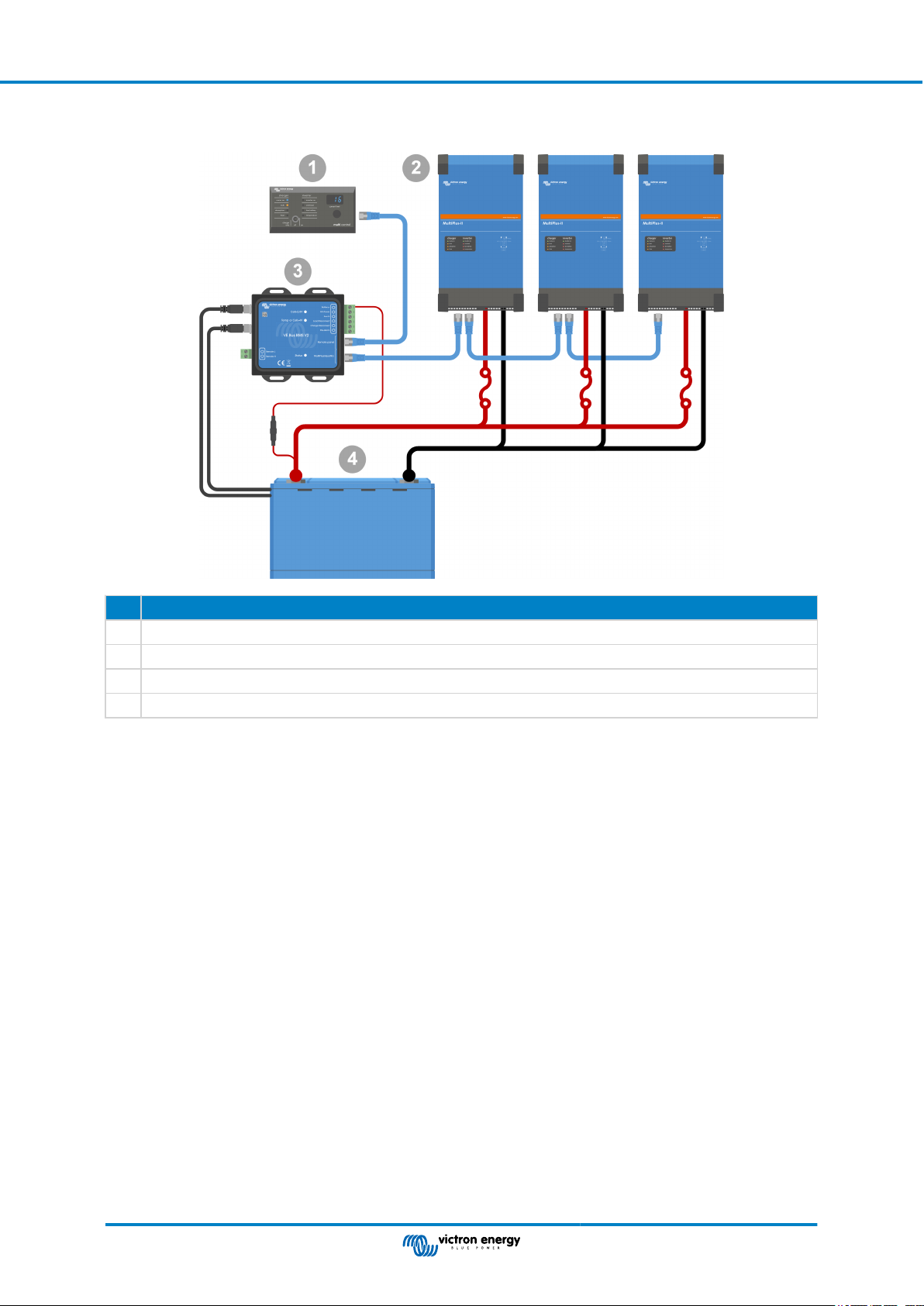
4.5. Three-phase system with a Digital Multi Control
# Description
1 Digital Multi Control
2 MultiPlus-II Inverter/charger installed and configured as a 3-phase system
3 VE.Bus BMS V2
4 Lithium Battery Smart or battery consisting of multiple batteries creating a 12V, 24V or 48V battery bank
Page 17 System examples
Page 20
VE.Bus BMS V2
5. Operation
5.1. Important warning
Lithium batteries are expensive and can be damaged due to over discharge or over charge. Damage due to over discharge can
occur if small loads (such as: alarm systems, relays, standby current of certain loads, back current drain of battery chargers
or charge regulators) slowly discharge the battery when the system is not in use. In case of any doubt about possible residual
current draw, isolate the battery by opening the battery switch, pulling the battery fuse(s) or disconnecting the battery plus when
the system is not in use.
A residual discharge current is especially dangerous if the system has been discharged completely and a low cell voltage
shutdown has occurred. After shutdown due to low cell voltage, a capacity reserve of approximately 1Ah per 100Ah battery
capacity is left in the battery. The battery will be damaged if the remaining capacity reserve is drawn from the battery. A residual
current of 10mA for example may damage a 200Ah battery if the system is left in discharged state for more than 8 days.
The shutdown due to low cell voltage by the BMS should always be used as a last resort to be on the safe side at all times. We
recommend not letting it get that far in the first place and instead shutting down the system automatically based on a defined state
of charge so that there is enough reserve capacity in the battery. For an inverter/charger, for example, this can be done via the
VE.Configure setting 'shut-down on SoC'. It is even easier with a BMV, whose relay can control the remote on/off port of the BMS
via an adjustable SoC value.
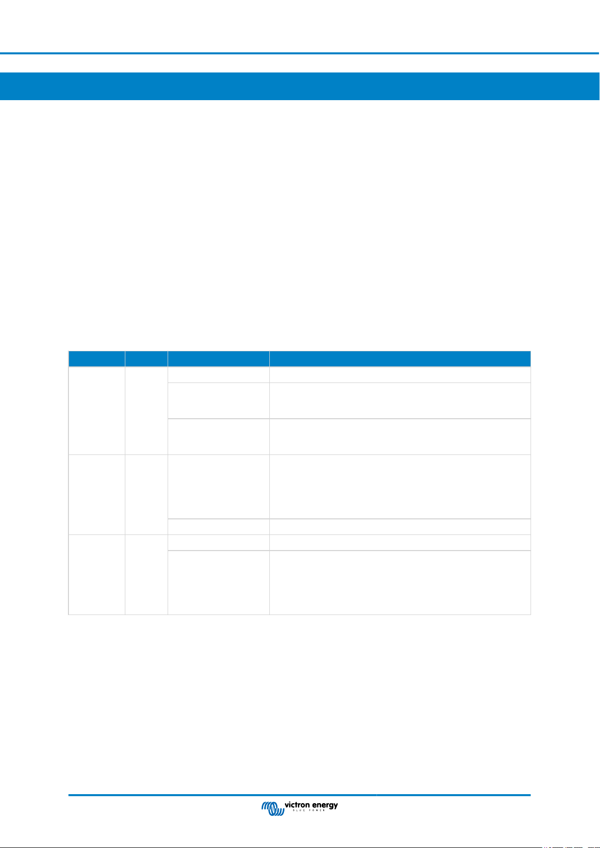
5.2. LED indications
LED Colour Behaviour Meaning
Off BMS is off
Lights shortly
Status Blue
Cell > 2.8V Blue
Cell > 4V Red
approximately once
every 10 seconds.
Flashes rapidly at
approximately 15 times
per second.
Off
On Cell voltage within normal range.
Off Cell voltage and temperature within normal range.
On
BMS is operating normally.
The BMS is stuck in boot loader mode due to a faulty application.
Low cell voltage.
The BMS has switched the DC loads and the inverter off.
Charge the battery or connect an AC supply to the inverter/charger.
Once the battery voltage has increased sufficiently, the DC loads
and inverter will be switched on again.
High cell voltage or high temperature.
The BMS has switched off the chargers.
Check for a faulty charger and/or reduce battery temperature.
Once the battery voltage and/or temperature have been sufficiently
reduced, the BMS will switch the chargers back on.
Page 18 Operation
Page 21
VE.Bus BMS V2
6. Updating the firmware
Updating the VE.Bus BMS V2 firmware can be carried out in two different ways:
1. Via VRM: Remote firmware update: This functionality requires the device to be updated by connecting it to a GX device
(Cerbo GX, Ekrano GX or other).
2. Update using VictronConnect or VEFlash (part of the VE Configuration tools for VE.Bus Products): This requires an MK3
USB interface.
Please note that updating the firmware using VictronConnect or VEFlash requires either an Android phone, a PC or an Apple
computer with macOS. Unfortunately, this is not possible with an iOS device.
Notes on firmware updating in general
• Newer is not always better.
• If it isn't broken, don't fix it.
• Be sure to read the changelog before starting the update process. The changelog can be downloaded from Victron
Professional.
Therefore, use this feature with caution. Our main advice is not to update a running system unless there are problems with it or if
a new feature included in the firmware is required for the installation. A firmware update should always be carried out for a new
installation.
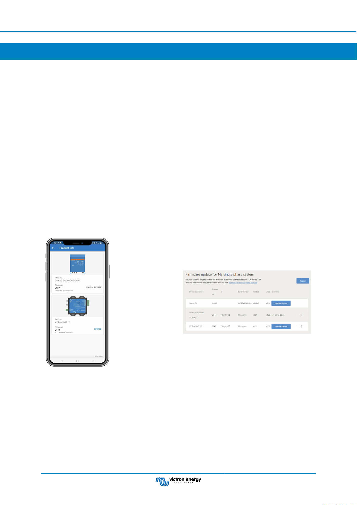
What firmware version do I have?
The firmware version is visible on the VictronConnect Product info page of the installed MultiPlus/Quattro and in VRM under
Device List → Firmware Update.
6.1. Updating the firmware using VRM: Remote firmware update
The comprehensive procedure for performing a firmware update remotely via VRM, known as VRM: Remote firmware update, is
carefully described in a separate manual and can be viewed here.
Additional notes
• Some warnings will appear before the update starts. Please read these carefully and take note of them. You have to confirm
each of them. Do not update if you do not fully understand the terms.
• Do not perform the update when the GX device is powered by the inverter/charger. During the update, the inverter/charger is
briefly switched off and on again.
• It is not possible to update the VE.Bus V2 in case there is also a Digital Multi Control connected to the VE.Bus network.
Page 19 Updating the firmware
Page 22
VE.Bus BMS V2
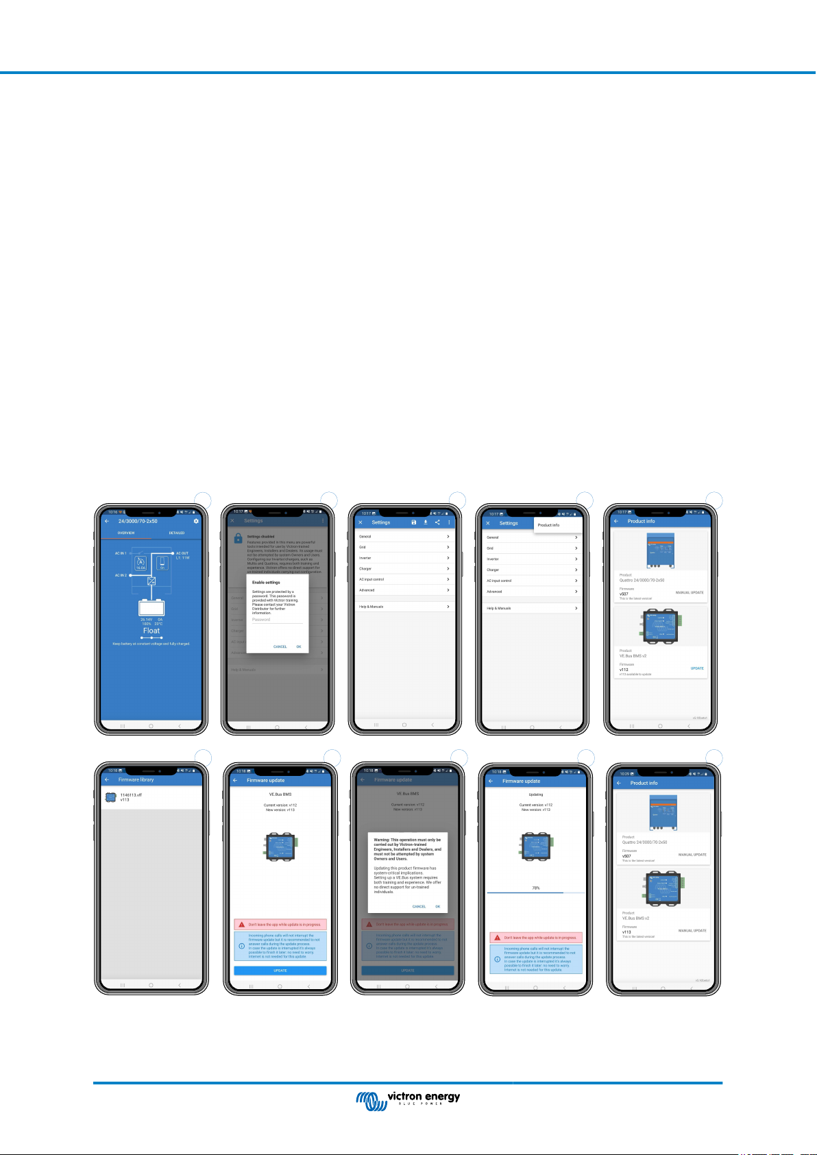
6.2. Updating the firmware using VictronConnect
To perform a firmware update via VictronConnect, it requires an MK3 USB interface, which connects to the VE.Bus network via
either an Android phone/tablet, a Windows PC or an Apple computer with macOS. Unfortunately, this is not possible with an
Apple iOS device.
Step-by-step
1. In VictronConnect, open the VE.Bus inverter/charger that is connected to the MK3 interface, and tap on the cog wheel icon to
get to the Settings page.
2. Since the settings are password protected, you need to enter the password in order to enable the settings.
Please contact your installer or Victron distributor for the password.
3. On the Settings page, tap on the three vertical dots.
4. Tap on Product info to get to the Product info page.
5. On the Product info page it will tell you if an update is available for VE.Bus BMS v2.
6. Tap Update to go to the firmware library, then tap the firmware file you want to use.
7. Tap on Update.
8. On the next screen, read the warning. Once you fully understand the implications, tap OK to start the firmware update.
9. Keep the VictronConnect app open while the update is in progress.
10. Once the update has been performed, the product information page will automatically reappear. Check whether the current
firmware number is displayed.
1
5432
109876
Page 20 Updating the firmware
Page 23

VE.Bus BMS V2
7. Frequently asked questions
Q1: I have disconnected the VE.Bus BMS V2, my inverter/charger will not switch on; why?
If the inverter/charger cannot find the BMS, it will go into an emergency mode. In this mode, the inverter/charger will charge the
batteries with a maximum of 5A, up to 12, 24 or 48V (depending on the system voltage). While the inverter/charger is in this
mode, only the "Mains on" LED is illuminated. If you disconnect the AC input, the inverter/charger will switch off and will not
start to invert since it cannot get verification on the battery health from the BMS. Note that when the batteries are depleted or
disconnected, a Quattro will need to be powered from AC input 1. Supplying power to AC input 2 will not make a Quattro switch
on and start charging.
Q2: The batteries are empty, and the inverter/charger will not start to charge; how to get the system up and running
again?
Connect a small battery charger, for example, a 5A charger, and wait for the battery voltage to get back up to 12, 24 or 48V
(depending on the system voltage).
Q3: What happens with the inverter/charger when the BMS gives a low cell voltage signal?
The inverter/charger will be set to "charger only mode", and the batteries are charged when an AC input is available. Should AC
not be available, the inverter/charger is off.
Q4: What happens with the inverter/charger when the BMS gives a high cell voltage signal?
The high cell voltage signal will only be given when there are unbalanced cells. The inverter/charger will switch to bulk and starts
charging with a reduced charge current. This allows the balancing system in the batteries to re-balance the cells.
Q5: What does it mean when the BMS displays a VE.Bus Error 15?
With VE.Bus firmware versions below version xxxx415 the VE.Bus BMS V2 will generate a VE.Bus Error 15, VE.Bus combination
error. This error indicates that the VE.Bus products or firmware versions cannot be combined. Resolution: Update the inverter/
charger to a firmware version xxxx415 or higher, if available.
Page 21 Frequently asked questions
Page 24
VE.Bus BMS V2
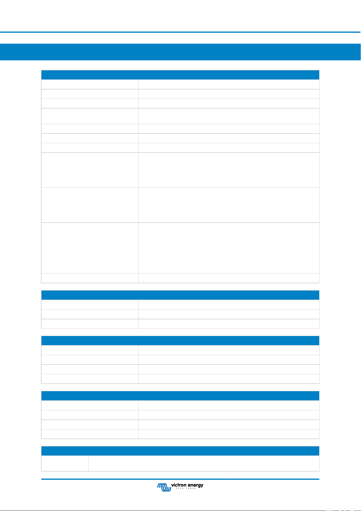
8. Technical specifications VE.Bus BMS V2
Electrical
Input voltage range 9 – 70Vdc
Current draw - regular operation 10mA (excluding Load disconnect current)
Current draw - low cell voltage 2mA
Current draw - switched off via remote
on/off terminal
GX-pow output 1A
Aux-in input 1A
Pre-alarm output current rating 1A, not short circuit protected
Load disconnect output Normally high (output voltage ≈ supply voltage – 1V)
Floating when the load needs to be disconnected
Charge disconnect output Normally high, (output voltage ≈ supply voltage – 1V)
Floating when charger should be disconnected
Source current limit: 10mA
Remote on/off terminals Usage modes to turn the system on or off:
a. ON when the L and H terminal are interconnected (switch or relay contact)
1.50mA
Source current limit: 1A
Sink current: 0A
Sink current: 0A
b. ON when the L terminal is pulled to battery minus (V<3.5V)
c. ON when the H terminal is high (2.9V < VH < Vbat)
d. OFF in all other conditions
VE.Bus communications ports 2 x RJ45 sockets to connect to all VE.Bus products
General
Operating temperature -20 to +50°C 0 - 120°F
Humidity Max. 95% (non-condensing)
Protection grade IP20
Enclosure
Material ABS
Colour Matt black with a blue sticker
Weight 120gr
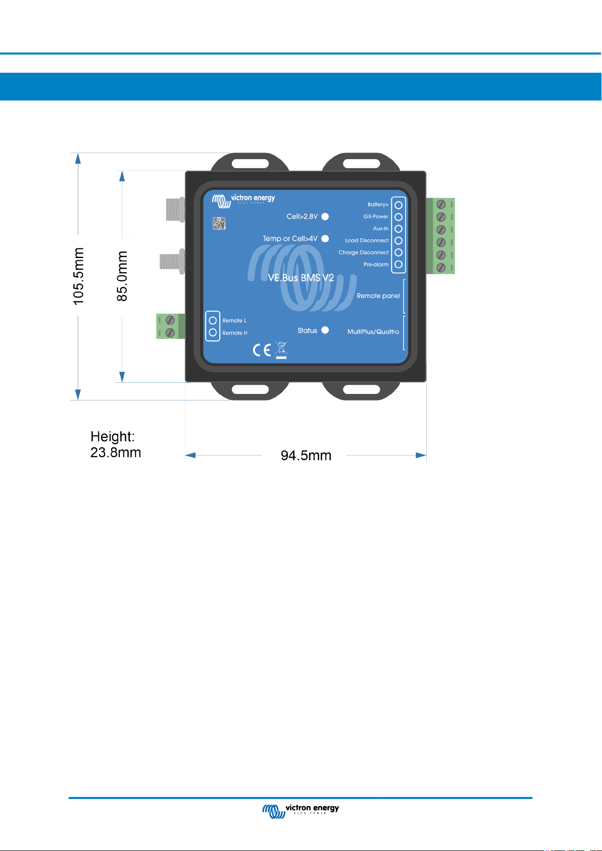
Dimension (h x w x d) 23.8mm x 94.5mm x 105.5mm
Standards
Safety EN 60950
Emission EN 61000-6-3, EN 55014-1
Immunity EN 61000-6-2, EN 61000-6-1, EN 55014-2
Automotive EN 50498
External AC-DC adapter
Min. power rating 1A@12V - If the nominal output voltage is > battery voltage, the AC-DC adapter takes over the power
supply of the GX device.
Technical specifications VE.Bus BMS
Page 22
V2
Page 25
9. Appendix
9.1. Dimensions VE.Bus BMS V2
VE.Bus BMS V2
Page 23 Appendix
Page 26

VE.Bus BMS V2
9.2. VE.Bus BMS V2 compared to VE.Bus BMS V1
This table highlights the differences between the VE.Bus BMS V2 compared to it's predecessor, the VE.Bus BMS V1.
Feature VE.Bus BMS V2 VE. Bus BMS V1
Product image
MultiPlus/Quattro VE.Bus port Yes Yes
Remote panel VE.Bus port
GX device communication
On/Off/Charger-only control
GX-Pow terminal
BMS firmware update
Inverter/charger "in system"
firmware update
Usable without a VE.Bus
connection
Load disconnect terminal Yes Yes
Pre-alarm terminal Yes Yes
Charge disconnect terminal Yes Yes
Remote on/off terminal Yes
Aux-In terminal
MultiPlus/Quattro enabled LED No Yes
Status LED
Low cell voltage LED Yes Yes
High cell voltage and/or
temperature LED
To connect a GX device, a VE.Bus
Smart dongle or a Digital Multi Control.
Yes, the BMS broadcasts operational
data and the BMS can control
equipment that is connected to a GX
device, like solar chargers and certain
AC chargers via DVCC.
Yes, via GX device and remotely via
VRM, VE.Bus Smart dongle and Digital
Multi Control.
Yes, the GX-Pow output supplies GX
power from either the battery or from
the Aux-In input, whichever voltage is
higher.
Yes, both locally and also remotely via
the VRM portal.
Yes, both locally and also remotely via
the VRM portal.
No. The BMS has no battery minus
connection, battery minus is supplied by
the VE.Bus and VE.Bus needs to be
connected for the BMS to be powered.
Yes, an AC-DC adapter or other power
supply connected to the Aux-In input
ensures that the GX device is also
powered during a low cell state as long
as that aux power is available.
Yes, this LED indicates that the BMS
is sending information frames to the
inverter/charger. The LED can also
indicate if the BMS is stuck in boot
loader mode.
Yes Yes
Only to connect a Digital Multi Control.
No
Only with Digital Multi Control.
No
Not possible
No, the VE.Bus BMS V1 needs to be
disconnected in order to update the
firmware of the inverter/charger.
Yes
No. If remote on/off control is needed, a
switch needs to be placed in the positive
power supply line to the BMS.
No
No
Page 24 Appendix
 Loading...