

Page 1
Manual
Handleiding
l
Anleitung
Manual
Skylla-i Con trol GX
EN
NL
Manue
FR
DE
ES
Appendix
Page 2

Page 3

Page 4
Connecting the Skylla-i panel to your Skylla-i charger is a simple procedure. Connect the two
RJ45 sockets which are internally connected, you can connect the cable to either socket.
State
LEDs:
Bulk
Absorption
Float
Alarm
Bulk
Safe-mode
Absorption
Automatic equalization
Float / storage
Manual equalization
Power supply mode
Alarm*
1. General
The Skylla-i panel is a remote panel designed to work with all Skylla-i chargers. The Skylla-i
charger uses the VE.CAN bus.
devices with a regular UTP (Unshielded Twisted Pair) cable with two RJ45 connectors. Make
sure that the two RJ45 bus terminators are in place at both ends. The Skylla-i panel comes
complete with both RJ45 bus terminators. Both the Sky lla-i charger and the panel have two
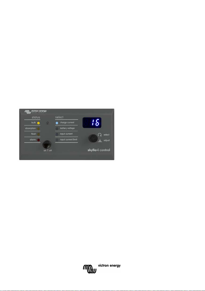
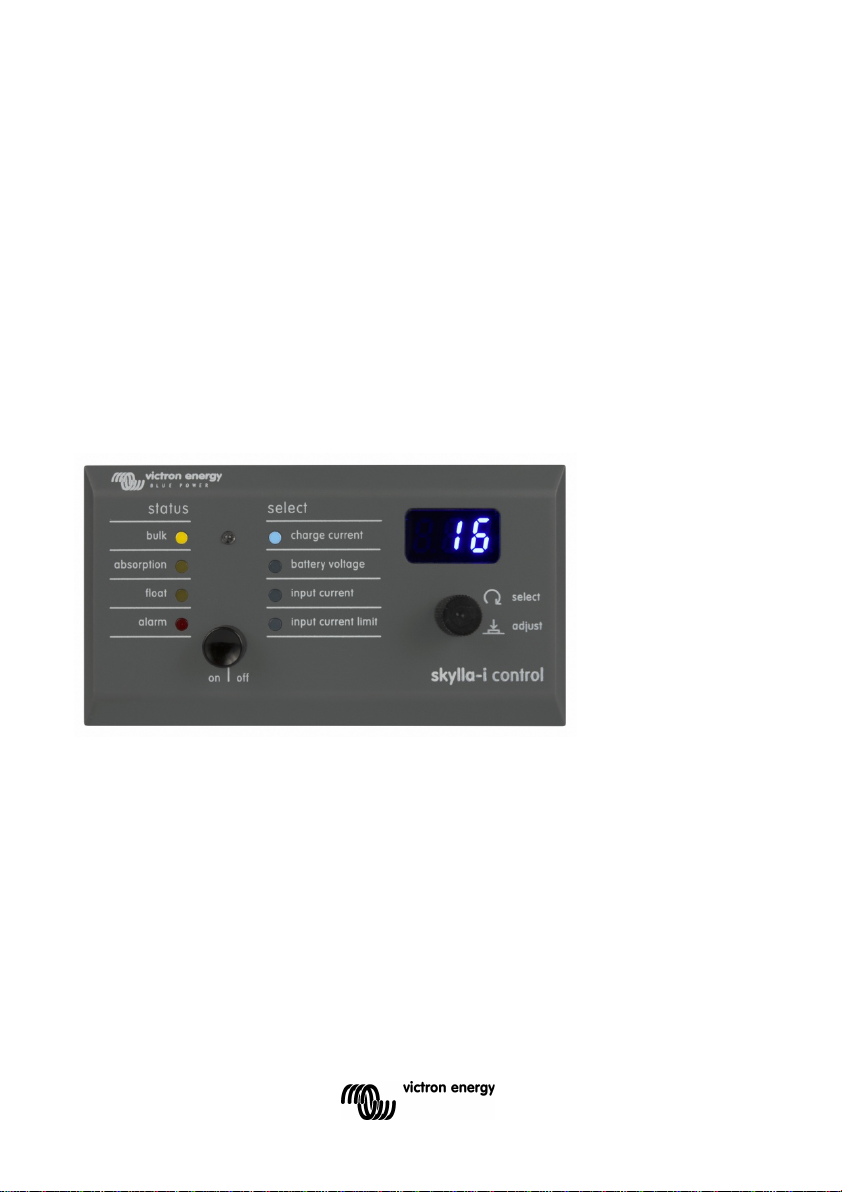
Operation
When the bus is powered-up the Skylla-i panel briefly lights up all items, next the software
version number is displayed after which it will show the status of the connected Skylla-i
charger.
When the Skylla-i charger is powered off (standby) the panel will also shutdown (all lights off)
to reduce power consumption.
When the Skylla-i charger is operating, the status LEDs show the actual state of charge. The
table below shows the possible LED indications during normal charge operation.
means permanent on means blinking means off
* When the 'alarm' LED is on, the display shows an error code. See appendix C for an overview of
the error codes.
During normal charger operation it is possible to cycle through the following parameters, by
turning the rotary knob:
• charge current
• battery voltage
• input current
• input current limit
EN NL FR DE ES Appendix
The active parameter is shown by a blue LED in the status area. The display shows parameters in
SI units (Ampere or Volts) with one decimal digit. The decimal digit disappears when the charger
operates at or above 100A.
The display will show the set value (blinking) when adjusting voltage or current with the
potentiometers in the Skylla-i.
1
Page 5
1.1 Turning the charger on and off
The Skylla-i charger is switched on and off by briefly pressing the on|off button. Note that the main
power switch on the charger is dominant, once it is switched off on the charger, the panel cannot
switch the charger on anymore.
1.2 Setting the charger input current limit
The input current limit is modified by briefly pressing and releasing the rotary knob. The selection
will automatically jump to input current limit if it was not yet active. Next the display shows the
actual input current limit and blinks. Turn the rotary now to modify the input current limit. To
confirm the new value either wait several seconds or briefly press and release the rotary knob.
1.3 LED brightness
For your comfort, the brightness of the LEDs is controlled automatically using a light sensor.
When the ambient light level becomes lower the LEDs will be less bright which is more pleasant
for the eye and reduces power consumption.
1.4 Multiple Skylla-i’s and Control panels in one VE.Can network
Several Skylla-i control panels can be connected to one charger or to a set of synchronized and
parallel connected chargers.
It is not necessary to configure anything in an out of the box installation. Connecting all Skylla-i’s,
the control panel and placing the terminators is sufficient. Only in installations where multiple
Skylla-i’s are on the same VE.Can network while charging different battery banks, do settings
need to be altered to prevent them from synchronizing. All Skylla-i chargers and Sk yll a-i control
panels recognize each other based on the device instance. The default device instance is zero for
both control panels and Skylla-i’s. To change the device instance, use a NMEA2000 network tool
from for example Actisense or Maretron.
To manually reset the device instance in the Skylla-i control panel to zero, press and hold the
pushbutton on the back for four seconds. After the four seconds the panel will restart (all LEDs will
temporary light up), and the device instance is set to zero.
See the latest version of the Skylla-i manual for the list of error and warning codes. Note that
mentioned functionality is available from firmware v2.00 in both the Skylla-i and the Skylla-i control
panel.
2
Page 6

De aansluiting van het Skylla-i paneel op uw Skylla-i lader is heel eenvoudig. Verbind de twee
dus u kunt de kabel op eender welk contact aansluiten.
Status
LED's:
Bulk
Absorption
Float
Alarm
Bulk
Beveiligingsmodus
Absorptie
Automatische egalisatie
Float / opslag
Handmatige egalisatie
Stroomvoorziening
Alarm*
1. Algemeen
Het Skylla-i paneel is een afstandpaneel ontworpen om te werken met alle Skylla-i
ladermodellen. De Skylla-i lader gebruikt de VE.CAN-bus.
toestellen met een gewone UTP-kabel (niet-afgeschermde kabel met gevlochten paar) met
twee RJ45 aansluitingen. Zorg ervoor dat de twee RJ45 bus-afsluiters op beide uiteinden op
hun plaats zitten. (Beide RJ45 bus-afsluiters worden meegeleverd met het Skylla-i paneel)
Zowel de Skylla-i lader als het paneel hebben twee RJ45 contacten die intern verbonden zijn,
Bediening
Wanneer de bus stroom ontvangt, lichten alle onderdelen van het Skylla-i paneel even op.
Vervolgens wordt het softwareversienummer weergegeven en daarna de status van de
aangesloten Skylla-i lader.
Wanneer de Skylla-i lader wordt afgezet (stand-by) wordt het paneel ook uitgeschakel d (alle
lampjes uit) om het stroomverbruik te verminderen.
Wanneer de Skylla-i lader in werking is, geven de status-LED's de huidige laadstatus weer. De
onderstaande tabel bevat de mogelijke LED-indicaties tijdens normaal laadbedrijf.
permanent opgelicht knippert uit
* Wanneer de LED van ‘alarm’ brandt wordt in het display een error code weergegeven. Zie
appendix C voor een overzicht van de error codes.
Tijdens normaal laadbedrijf is het mogelijk om met de draaiknop de volgende parameters weer te
geven:
• charge current (laadstroom)
• battery voltage (accuspanning)
• input current (ingangsstroom)
• input current limit (ingangsstroomlimiet)
EN NL FR DE ES Appendix
De actieve parameter wordt weergegeven aan de hand van een blauwe LED in het statusvak. De
display geeft de parameters in SI-eenheden (Ampère of Volt) met één decimaal teken weer. Het
decimale teken verdwijnt wanneer de lader aan 100 A of meer werkt.
Het display toont de ingestelde waarde (knipperend) als de spanning of stroom met de
potentiometers in de Skylla-i wordt aangepast.
1
Page 7
1.1 De lader aan en uit zetten
De Skylla-i lader kan aan en uit worden gezet door even op de aan/uit knop te drukken. Merk op
dat de hoofdstroomschakelaar op de lader voorrang heeft: eenmaal uitgezet op de lader, kan het
paneel de lader niet meer aan zetten.
1.2 De ingangsstroomlimiet van de lader instellen
De ingangsstroomlimiet kan worden gewijzigd door de draaiknop even in te drukken en los te
laten. De selectie springt automatisch op ingangsstroomlimiet als deze parameter nog niet actief
was. Vervolgens geeft de display de huidige ingangsstroomlimiet knipperend weer. Draai nu aan
de draaiknop om de waarde te wijzigen. Om de nieuwe waarde te bevestigen, wacht u een aantal
seconden of drukt u de draaiknop even in.
1.3 Helderheid van de LED's
Voor uw gemak wordt de helderheid van de LED's automatisch gestuurd op basis van een
lichtsensor. Wanneer het niveau van het omgevingslicht daalt, worden de LED's minder helder,
wat aangenamer is voor de ogen en waardoor het stroomverbruik afneemt.
1.4 Meerdere Skylla-i’s en bedieningspanelen in één VE.Can-netwerk
Er kunnen meerdere Skylla-i bedieningspanelen op één lader of op een set gesynchroniseerde en
parallel geschakelde laders worden aangesloten.
Voor een gebruiksklare installatie is geen configuratie nodig. Het aansluiten van alle Skylla-i’s, het
bedieningspaneel en het plaatsen van de afsluiters is voldoende. Alleen in installaties, waar
meerdere Skylla-i’s tijdens het laden van verschillende accubanken op hetzelfde VE.Can-netwerk
zitten, moeten de instellingen worden aangepast om synchronisatie te voorkomen. De Skylla-i
acculaders en de Skylla-i bedieningspanelen herkennen elkaar aan de hand van het
toestelnummer. Het standaard toestelnummer voor zowel de bedieningspanelen als de Skylla-i’s
is nul. Gebruik om het toestelnummer te veranderen een NMEA2000 netwerktool van bijvoorbeeld
Actisense of Maretron.
Om het toestelnummer in het Skylla-i bedieningspaneel handmatig terug op nul te zetten, houdt u
de drukknop aan de achterkant vier seconden ingedrukt. Na vier seconden wordt het paneel
opnieuw opgestart (alle LEDS lichten even op) en staat het toestelnummer op nul.
2
Page 8

Zie de nieuwste versie van de Skylla-i handleiding voor een lijst met storings- en
waarschuwingscodes. Opmerking: De vermelde functionaliteit is beschikbaar vanaf firmware
versie 2.00 in zowel de Skylla-i als ook het Skylla-i bedieningspaneel.
EN NL FR DE ES Appendix
3
Page 9

Page 10

Raccorder le tableau de commande Skylla-i à votre chargeur Skylla-i est une procédure très
pouvez connecter le câble à n'importe laquelle des deux prises :
État
LED :
Bulk
Absorption
Float
Alarme
Bulk
Mode sécurité
Absorption
Égalisation automatique
Float / veille
Égalisation manuelle
Mode alimentation électrique
Alarme*
1. Généralités
Le tableau de commande Skylla-i est un tableau de commande à distance conçu pour
travailler avec tous les modèles de chargeurs Skylla-i. Le chargeur Skylla-i utilise le bus
VE.CAN.
simple. Il suffit de raccorder les deux dispositifs avec un câble UTP (paire torsadée non
blindée) ordinaire ayant deux connecteurs RJ45. Assurez-vous que les deux terminateurs du
bus RJ45 sont bien placés aux deux extrémités. Le tableau de commande Skylla-i est livré
avec deux terminaisons de Bus RJ45. Le chargeur Skylla-i et le tableau de commande
disposent tous les deux de deux prises RJ45 qui sont raccordées au niveau interne. Vous
Fonctionnement
Quand le bus est mis sous tension, le tableau de commande Skylla-i allume brièvement tous
les éléments. Ensuite s'affiche le numéro de version du logiciel suivi du statut du chargeur
Skylla-i qui est connecté.
Quand le chargeur Skylla-i est mis hors tension (veille), le tableau s'éteindra également (toutes
les lumières éteintes) afin de réduire la consommation d'énergie.
Si le chargeur Skylla-i est en marche, les LED de statut montrent son état de charge actuel. Le
tableau ci-dessous montre les éventuelles indications LED pouvant s'afficher pendant une
opération de charge normale.
signifie allumé en permanence signifie clignotant signifie éteint
* Quand la LED d'alarme est allumée, l'écran affiche un code d'erreur. Voir annexe C pour
connaître les codes d'erreur.
Pendant le fonctionnement normal du chargeur, il est possible de sélectionner les paramètres
suivants en tournant le bouton rotatif :
• Courant de charge
• Tension de batterie
• Courant d'entrée
• Limite de courant d'entrée
EN NL FR DE ES Appendix
Le paramètre actif est indiqué par une LED de couleur bleu dans la zone d'état. L'écran montre
les paramètres en unités SI (ampères ou volts) avec un chiffre décimal. Le chiffre décimal
disparaît quand le chargeur fonctionne à 100 A ou plus.
Sur le Skylla-i, l'écran affichera la valeur définie (clignotante) lors du réglage de la tension ou du
courant avec les potentiomètres.
1
Page 11

1.1 Allumer et éteindre le chargeur
Le chargeur Skylla-i s'allume ou s'éteint en appuyant brièvement sur le bouton de marche/arrêt
(on/off). Remarque : l'action de l'interrupteur principal du chargeur prédomine, et une fois qu'il est
en position éteinte sur le chargeur, le tableau ne peut plus allumer le chargeur.
1.2 Configurer la limite de courant d'entrée du chargeur
La limite de courant d'entrée peut se modifier en appuyant brièvement sur le bouton rotatif et en le
relâchant. La sélection sautera automatiquement à la limite de courant d'entrée si elle n'était pas
encore active. Ensuite, l'écran montre la limite de courant d'entrée réelle et clignote. Tournez le
bouton rotatif pour modifier la limite de courant d'entrée. Pour confirmer la nouvelle valeur, soit
vous attendez plusieurs secondes, soit vous appuyez et relâchez brièvement le bouton rotatif.
1.3 Luminosité des LED
Pour votre confort, la luminosité des LED est contrôlée automatiquement par un capteur de
lumière. Quand le niveau de la lumière ambiante diminue, les voyants LED seront moins brillants
ce qui sera plus agréable pour les yeux et réduira la consommation d'énergie.
1.4 Connecter plusieurs tableaux de commande et chargeurs Skylla-i sur
un seul réseau VE.Can
Plusieurs tableaux de commande Skylla-i peuvent être connectés à un chargeur ou à un
ensemble de chargeurs connectés en parallèle et synchronisés.
Aucune configuration n'est nécessaire pour les produits prêts à l'emploi. Le fait de connecter tous
les Skylla-i, le tableau de commande et installer les terminateurs est suffisant. Uniquement dans
le cas d'installations où plusieurs Skylla-i se trouvent sur le même réseau VE.Can pour charger
différents bancs de batterie, les paramètres doivent être modifiés pour éviter qu'ils se
synchronisent. Des chargeurs Skylla-i et des tableaux de commande Skylla-i se reconnaissent les
uns des autres grâce à l'instance du dispositif. L'instance du dispositif par défaut est zéro à la fois
pour les panneaux de commande et les Skylla-i. Pour modifier l'instance du dispositif, utilisez un
outil-réseau NMEA2000 comme par exemple Actisen ou Maretron.
Pour remettre à zéro manuellement l'instance du dispositif dans le tableau de commande Skylla-i,
appuyez sans relâcher pendant 4 secondes sur le bouton-poussoir se trouvant à l'arrière. Après 4
secondes, le tableau de commande redémarrera (toutes les LED s'allumeront temporairement), e t
l'instance du dispositif sera à zéro.
2
Page 12

Consultez la dernière version du manuel du Skylla-i pour connaître la liste d'erreur et les codes
d'avertissement. Remarquez que la fonctionnalité mentionnée est disponible depuis le
microprogramme v2.00 aussi bien pour le Skylla-i que pour le tableau de commande Skylla-i.
EN NL FR DE ES Appendix
3
Page 13

Page 14

Das Anschließen des Skylla-i Paneels an Ihr Skylla-i Ladegerät ist recht einfach. Verbinden
Kabel an jeder der Buchsen anschließen.
Ladeerhaltungs
e
Alarm
Konstantstromphas
e
sicherer Modus
Konstantspannung
sphase
Automatischer
Zellenausgleich
Ladeerhaltungsspa
Lagerungsmodus
manueller
Zellenausgleich
Stromversorgungs
modus
Alarm*
1. Allgemein
Das Skylla-i Paneel ist ein Fernbedienpaneel, das zum Betrieb mit allen Skylla-i LadegerätModellen entworfen wurde. Das Skylla-i Ladegerät nutzt den VE.CAN Bus.
Sie die beiden Geräte mit einem normalen UTP (Unshielded Twisted Pair) -Kabel (Kabel mit
ungeschirmten Paaren) mit zwei RJ45 Steckern. Überprüfen Sie, ob die beiden RJ45 BusAbschlussstecker an beiden Enden vorhanden sind. Das Skylla-i-Paneel wird komplett mit
beiden RJ45 Bus-Abschlusswiderständen geli efert. Sowohl das Sk ylla-i Ladegerät, als auch
das Paneel verfügen über zwei RJ45 Buchsen, die intern verbunden sind. Sie können das
Betrieb
Wird der Bus mit Strom versorgt, leuchten auf dem Skylla-i-Paneel kurz alle Symbole auf,
dann wird die Nummer der Software-Version angezeigt. Schließlich wird der Status des
angeschlossenen Skylla-i-Ladegerätes angezeigt.
Wird das Skylla-i-Ladegerät ausgeschaltet (Standby-Betrieb), schaltet sich ebenso das Paneel
aus (sämtliche Lichter werden abgeschaltet), um den Stromverbrauch zu senken.
Ist das Skylla-i-Ladegerät in Betrieb, zeigen die Status-LEDs den aktuellen Ladezustand an.
Die folgende Tabelle zeigt die möglichen LED-Anzeigen während eines normalen
Ladebetriebs.
Status LEDs:
Konstantstrom
phase
Konstantspannun
gsphase
spannungsphas
EN NL FR DE ES Appendix
nnung/
bedeutet leuchtet ununterbrochen bedeutet blinkt bedeutet aus
* Wenn die ‘Alarm’- LED leuchtet, zeigt das Display einen Fehlercode an. In Anhang C finden Sie
eine Übersicht über die Fehlercodes.
Während des normalen Ladebetriebs kann man mithilfe des Drehknopfes zyklisch durch folgende
Parameter schalten:
• Charge current (Ladestrom)
• Battery voltage (Batteriespannung)
1
Page 15

• Input Current (Eingangsstrom)
• Input Current Limit (Eingangsstrombegrenzung)
Der jeweils aktive Parameter wird durch eine blaue LED im Statusbereich angezeigt. Das Display
zeigt die Parameter in SI-Einheiten (Ampere oder Volt) mit einer Dezimalzahl an. Die Dezimalzahl
verschwindet, wenn das Ladegerät bei oder über 100 A in Betrieb ist.
Das Display zeigt den eingestellten Wert (blinkend) an, wenn die Spannung oder der Strom über
das Potentiometer am Sykally-i eingestellt wird.
1.1 Ein- und Ausschalten des Ladegerätes
Das Skylla-i-Ladegerät wird durch ein kurzes Drücken des Ein-/Aus-Knopfes ein- bzw.
ausgeschaltet. Man beachte, dass der Hauptstromschalter am Ladegerät vorherrschend ist. Ist
dieser am Ladegerät ausgeschaltet, lässt sich dieses nicht mehr durch das Paneel einschalten.
1.2 Einstellung der Eingangsstrombeg re n zung des Ladegeräts
Die Eingangsstrombegrenzung lässt sich durch drücken und loslassen des Drehknopfes
verändern. Es wird dann automatisch die Eingangsstrombegrenzung ausgewählt, sofern diese
noch nicht aktiviert war. Als nächstes erscheint auf dem Bildschirm die aktuelle
Eingangsstrombegrenzung. Sie blinkt. Durch Drehen des Drehknopfes kann der Wert der
Eingangsstrombegrenzung verändert werden. Zur Bestätigung des neuen Wertes warten Sie
entweder einige Sekunden lang oder betätigen Sie kurz den Drehknopf.
1.3 Helligkeit der LED
Die Helligkeit der LEDs wird bequem automatisch über einen Lichtfühler gesteuert. Nehmen die
Lichtverhältnisse der Umgebung ab, leuchten die LEDs weniger hell. Dies ist angenehmer für die
Augen und verringert außerdem den Stromverbrauch.
1.4 Mehrere Skylla-i’s und Bedien-Paneele in einem VE.CAN-Netzwerk
Mehrere Skylla-i Steuerpaneele lassen sich mit einem Ladegerät verbinden bzw. mit einem Set
synchronisierter und parallelgeschalteter Ladegeräte.
Bei einer betriebsbereit gelieferten Instal lati on m uss nichts konfiguri ert werden. Es ist ausreichend,
alle Skylla-i-Geräte und das Bedienpaneel anzuschließen sowie die Abschlusswiderstände
2
Page 16

anzubringen. Nur bei Installationen, bei denen mehrere Skylla-i-Geräte sich im selben
VE.Can-Netzwerk befinden, während sie unterschi edl ic he Batteriebänke laden, müssen die
Einstellungen geändert werden, damit die Geräte sich nicht synchronisieren. Skylla-iLadegeräte und Skylla-i-Bedienpaneel erkennen sich aufgrund der Geräteinstanz. Die
Standard-Geräteinstanz ist sowohl für Bedienpaneele als auch für Skylla-i-Geräte Null.
Verwenden Sie zur Änderung der Geräteinstanz ein NMEA2000 Netzwerk-Tool, zum Beispiel
Actisense oder Maretron.
Um die Geräteinstanz beim Skylla-i-Bedien-Paneel manuell auf Null zurückzusetzen, halten
Sie den Druckknopf auf der Rückseite vier Sekunden lang gedrückt. Nach diesen vier
Sekunden startet das Paneel neu (sämtliche LEDS leuchten kurzzeitig auf). Die Geräteinstanz
ist dann auf Null gesetzt.
Beachten Sie auch die neuste Version des Skylla-i-Handbuchs. Dieses enthält eine Liste der
Fehler- und Warn-Codes. Bitte beachten Sie, dass die genannten Funktionen ab der Firmware
v.2.00 sowohl bei dem Skylla-i als auch dem Skylla-i-Bedienpaneel verfügbar sind.
EN NL FR DE ES Appendix
3
Page 17

Page 18

Conectar el Skylla-i a su sistema es un procedimiento sencillo. Conecte los dos dispositivos
conectar el cable a cualquiera de ellas.
Carga
inicial
Alarma
Carga inicial
Modo Seguro
Absorción
Ecualización automática
Flotación/almacenamiento
Ecualización manual
Modo fuente de alimentación
Alarma*
1. General
El panel Skylla-i es un panel remoto diseñado para trabajar con todos los modelos de
cargador Skylla-i. El cargador Skylla-i utiliza el Bus VE.CAN.
entre sí con un cable UTP normal (par trenzado no apantallado) y dos conectores RJ45.
Asegúrese de que hay dos terminadores de bus RJ45 colocados en ambos extremos. El panel
Skylla-i se suministra completo, con ambos terminadores de bus RJ45. Tanto el cargador
Skylla-i como el panel disponen de dos entradas RJ45 conectadas internamente, pudiéndose
Funcionamiento
Al encender el bus, el panel Skylla-i ilumina brevemente todos sus elementos, a continuación
muestra el número de versión del software y después el estado del cargador Skylla-i
conectado.
Al apagar el cargador Skylla-i (en espera) el panel también se apagará (todas las luces
apagadas) para reducir el consumo de energía.
Cuando el cargador Skylla-i está en funcionamiento, los LED de estado muestran el estado
real de la carga. La tabla siguiente muestra las posibles indicaciones LED durante una
operación de carga normal.
Estado LED:
encendido parpadeando apagado
* Cuando el LED "alarma" está encendido, la pantalla muestra un código de error. Consulte el
listado de códigos de error en el apéndice C.
Durante el funcionamiento normal como cargador, es posible reiniciar los siguientes parámetros,
girando el selector giratorio:
• corriente de carga
• tensión de la batería
• corriente de entrada
• límite de corriente de entrada
Absorción Flotación
EN NL FR DE ES Appendix
El parámetro activo se muestra mediante un LED azul en la zona de estado. La pantalla muestra
parámetros en unidades SI (amperes o voltios) con un decimal. El decimal desaparece cuando el
cargador funciona a 100A o más.
En el Skylla-i, la pantalla mostrará el valor establecido (parpadeando) al ajustar la tensión o
corriente con los potenciómetros.
1
Page 19

1.1 Encendido y apagado del cargador
El cargador Skylla-i se enciende o apaga pulsando brevemente el botón "on|off". Tenga en
cuenta que el interruptor principal del cargador es el que domina; si este interruptor se apaga, el
cargador ya no se podrá encender desde el panel.
1.2 Ajuste del límite de corriente de entrada del cargador
El límite de corriente de entrada se modifica pulsando brevemente y soltando el selector giratorio.
La selección se pondrá automáticamente en modo de límite de corriente de entrada, si no lo
estuviese todavía. A continuación, la pantalla parpadeará mostrando el límite de corriente de
entrada actual. Gire el selector ahora para modificar el límite de corriente de entrada. Para
confirmar el nuevo valor puede esperar varios segundos, o pulsar brevemente y soltar el selector
giratorio.
1.3 Luminosidad de los LED
Para su comodidad, la luminosidad de los LED se controla automáticamente por medio de un
fotosensor. Cuando disminuye la luminosidad ambiental, los LED brillarán menos, lo cual es más
agradable para los ojos y reduce el consumo de energía.
1.4 Conexión de varios Skylla-i y sus paneles de control a una red
VE.Can
Pueden conectarse varios paneles de control Skylla-i a un cargador o a un conjunto de
cargadores sincronizados y conectados en paralelo.
No es necesaria configuración alguna en la primera instalación. Es sufiencie con conectar todos
los Skylla-i, el panel de control y colocar los terminadores. Sólo en instalaciones en las que
múltiples Skylla-i están conectados a la misma red V.E.Can mientras cargan distintas bancadas
de baterías necesitan modificarse para evitar que se sincronicen. Los cargadores Skylla-i y los
paneles de control Skylla-i se reconocen unos a otros en base a su instancia de dispositivo. La
instancia de dispositivo por defecto es cero, tanto para el panel de control como para el Skylla-i.
Para cambiar la instancia de dispositivo, utilice una herramienta de red NMEA2000, como
Actisense or Maretron.
Para poner a cero manualmente la instancia de dispositivo en el panel de control Skylla-i, pulse y
mantenga pulsado el botón de la parte trasera durante cuatro segundos. Pasados los cuatro
segundos el panel se reiniciará (todos los LED se encenderán
2
Page 20

momentáneamente) y la instancia de dispositivo se pondrá en cero.
Consulte en la última versión del manual del Skylla-i el listado de errores y códigos de aviso.
Tenga en cuenta que la funcionalidad mencionada sólo está disponible en el firmware v2.00,
tanto en el Skylla-i como en el panel de control Skylla-i.
EN NL FR DE ES Appendix
3
Page 21

Page 22

Appendix A – Troubleshooting
EN:
If you are unable to establish a connection to your Skylla-i charger and you are sure that the
cabling is ok and VE.Can terminators are in place, first check the power-up sequence by
reconnecting the panel (this should show the power-up sequence) so you can determine if the
bus power is present.
When the connection is lost during operation (e.g. broken cable, cable unplugged) the red
alarm led will blink and the display will show "NC." to indicate that it no longer receives data
from the charger. The charger will keep its input current limit setting unless you power cycle
the charger with the main switch: when the charger does not detect the panel, it will fall-back to
default values (i.e. maximum allowed input current). Reconnecting the panel will restore the
previously selected input current limit.
NL:
Als u geen verbinding kunt maken met uw Skylla-i lader en u bent er zeker van dat de
bekabeling in orde is en de CAN-bus afsluitingen op hun plaats zitten, controleer dan eerst de
inschakelprocedure door het paneel opnieuw aan te sluiten (hierdoor moet de
inschakelprocedure worden weergegeven) zodat u kunt nagaan of de bus stroom ontvangt.
Als de verbinding tijdens bedrijf verloren gaat (bv. beschadigde kabel, kabel uitgetrokken), dan
knippert de rode alarm led en geeft het display "NC." weer om aan te geven dat er niet langer
gegevens van de lader worden ontvangen. De lader behoudt de instelling van de
ingangsspanningslimiet, tenzij u de lader uit en opnieuw aan zet met de hoofdschakelaar:
wanneer de lader het paneel niet detecteert, worden de fabriekswaarden toegepast (m.a.w.
maximum toegelaten ingangsstroom). Door het paneel opnieuw aan te sluiten, wordt de eerder
geselecteerde ingangsstroomlimiet opnieuw ingesteld.
FR:
Si vous n'arrivez pas à établir une connexion avec votre chargeur Skylla-i, et si vous êtes sûr que
le câblage est correctement installé et que les terminateurs du bus CAN sont bien en place,
vérifiez d'abord la séquence de mise sous tension en reconnectant le tableau de commande (il
doit montrer la séquence de mise sous tension) afin de déterminer si le bus est correctement
alimenté.
Si la connexion est perdue en cours de fonctionnement (par ex. câble endommagé, câble
débranché), la LED rouge de l'alarme clignotera et l'écran montrera « NC » pour indiquer qu'il ne
reçoit plus d'information de la part du chargeur. Le chargeur gardera sa configuration de limite de
courant d'entrée, à moins que vous arrêtiez/démarriez le chargeur avec l'interrupteur princi pal : si
le chargeur ne détecte pas le tableau de commande, il reprendra les valeurs par défaut (c.à.d. la
limite de courant d'entrée permise). En reconnectant le tableau de commande, cela rétablira la
limite de courant d'entrée qui avait été sélectionnée auparavant.
EN NL FR DE ES Appendix
1
Page 23

DE:
Wenn Sie keine Verbindung zu Ihrem Skylla-i-Ladegerät herstellen können, jedoch sicher sind,
dass die Verkabelung in Ordnung ist und die CAN-Bus-Abschlüsse angebracht sind, überprüfen
Sie zunächst die Einschaltfolge. Hierzu schließen Sie das Paneel erneut an (dies zeigt die
Einschaltfolge an). So lässt sich beurteilen, ob die Bus-Stromversorgung vorhanden ist.
Wird die Verbindung während des Betriebs unterbrochen (z. B. durch ein defektes Kabel, ein
abgetrenntes Kabel) blinkt die rote Alarm-LED und auf dem Display erscheint "NC", um
anzuzeigen, dass keine Daten mehr vom Ladegerät empfangen werden. Die am Ladegerät
eingestellte Eingangsstrombegrenzung geht nicht verloren, es sei denn, sie schalten das
Ladegerät mit dem Hauptschalter aus und wieder ein. Erkennt das Ladegerät das Paneel nicht,
verwendet es wieder die Standardwerte (d. h. den maximal zulässigen Eingangsstrom). Durch
das erneute Anschließen des Paneels wird die zuvor gewählte Eingangsstrombegrenzung wieder
hergestellt.
ES:
Si no pudiera establecer una conexión con su cargador Skylla-i y es tá seguro de que el cableado
es correcto y que los terminadores CAN-bus están en su sitio, compruebe primero la secuencia
de encendido reconectando el panel (de esta manera se muestra la secuencia de encendido)
para poder determinar si hay tensión en el Bus.
Cuando se pierde la conexión durante el funcionamiento (p.ej. cable roto o desconectado) el LED
rojo de alarma parpadeará y la pantalla mostrará (NC) para indicar que ya no recibe datos del
cargador. El cargador mantendrá su límite de corriente de entrada a menos que reinicie el
cargador, apagándolo y volviéndolo a encender desde el interruptor principal: si el cargador no
detecta el panel, revertirá a los valores por defecto (esto es, a la corriente de entrada máxima
permitida). Al reconectar el panel se restaurarán los valores de límite de corriente de entrada
previamente seleccionados.
2
Page 24

RJ45 VE.Can Terminator
Appendix B – Wiring diagram
EN NL FR DE ES Appendix
3
Page 25

Error nr.
Description
Action
E 2
Battery voltage too high
This error will reset after the battery voltage has
battery voltages programmed.
E 3
Remote Tsense+
connected to BAT-
Check if the Temperature sensor connector is
E 5
Remote temperature
Switch off the charger and check the sensor
OK LED is lit!
E 6
E 7
Vsense+ is low
Vsense- is high
Check the wiring between battery and Voltage
sensor connector. Check for polarity.
E 8
Voltage sense connection
Check the wiring between battery and Voltage
LED is lit!
E 9
Too large voltage drop
Check if the charge-cable wire size is large
size.
Appendix C – Error codes
This table lists the error code shown on the Skylla-i Control panel.
dropped.
This error can be tripped if the battery is charged
by several independent chargers that have other
E 4
connected to BAT+
Remote Tsense+
sensor broken during
operation.
to battery lost during
charging.
properly connected to a remote temperature
sensor.
cabling, if the cabling is ok replace the sensor.
Warning:
After a power-up with a suspected faulty sensor
(open connection) the error will be gone. The
charger will not see a remote temperature sensor
because the connection is open, and will ass ume
that no sensor is connected and will charge the
battery without temperature compensation!
After replacing a suspected temperature sensor,
DO NOT just apply a new power-up, but powerup and directly check if the Temperature sensor
sensor connector.
Check the FUSE in the Vsense+ lead near the
battery.
Attention:
After a power-up with a suspected broken
voltage sense-lead (open connection) the error
will be gone. The charger will not see a remote
voltage sensor because the connection is open,
and will assume that no voltage sense leads are
connected to the battery, and will charge the
battery without voltage compensation.
After replacing a suspected voltage sense lead,
DO NOT just apply a new power-up, but powerup and directly check if the Voltage sensor OK
4
over battery cables during
charging.
enough to handle the charging current.
This error can also be generated by corroded
connections of the battery poles.
Check poles. Tighten if necessary. Check wire
Page 26

E17
Charger overheated
Error will reset after charger has cooled down.
regard to cooling.
E18
Charger over-current
The charge-circuit is damaged.
power sources and call service.
E20
Maximum Bulk-time
This error can only occur when the MAX bulk-
protection.
E34
Mains over-current
The mains current has exceeded 20A. This error
persists--> call service.
116
Internal error
Disconnect the charger from all power-sources,
service.
CFG
Configuration problem
The control panel detected more than one Skylla-
panels in one VE.Can network’.
NC
No connection
The control panel cannot connect to a Skylla-i in
the VE.Can network.
If error persists, check the ambient temperature
and check for obstructions near the air inlet and
outlet holes of the charger cabinet.
Check manual for mounting instructions with
Disconnect charger from all power-sources, wait
3 minutes, and power up again.
If error persists--> disconnect charger from
EN NL FR DE ES Appendix
exceeded
(calibration data lost)
time protection is active (see paragraph 8.10).
This error is generated when the batteryabsorption-voltage is not reached after 10 hours
of charging.
For normal house-hold solar installations it is
advised do de-activate the MAX bulk-time
could be generated during an internal system
fault.
Disconnect the charger from all power-sources,
wait 3 minutes, and power-up again. If the error
wait 3 minutes, and power-up. If error persists-->
disconnect charger from power sources and call
in the VE.Can network with the sam e device
instance. It is not possible to connect one control
panel to multiple Skylla-i chargers. See the
chapter titled ‘Multiple Skylla-i’s and Control
5
Page 27

6
Page 28

Page 29

Victron Energy Blue Power
Victron Energy B.V.
www.victronenergy.com
Distributor:
Serial number:
Version : 05
Date : 16 February 2016
De Paal 35 | 1351 JG Almere
PO Box 50016 | 1305 AA Almere | The Netherlands
General phone : +31 (0)36 535 97 00
Customer support desk : +31 (0)36 535 97 03
Fax : +31 (0)36 535 97 40
E-mail : sales@victronenergy.com
 Loading...