

Page 1

Victron Energy B.V. | De Paal 35 | 1351 JG Almere | The Netherlands
www.victronenergy.com
1. Introduction
2. Engine on detection sequence
0 1:
1 2:
2 3:
3 4:
4 5:
Engine-on detection set-up Orion-Tr Smart DC-DC Charger
www.victronenergy.com
The engine on detection mechanism simplifies your Orion-Tr Smart DC-DC Charger system by detecting if the engine is
running without wiring additional switches or sensors. The factory default setting of the engine on detection is based on
a generic smart alternator system which can be re-configured with the VictronConnect app.
The VictronConnect app can be downloaded from:
http://www.victronenergy.nl/support-and-downloads/software/
Use the manual – VictronConnect - to get the most out of the VictronConnect App when it’s connected to an Orion
Smart: https://www.victronenergy.com/live/victronconnect:start
Configuring the engine on detection depends on the voltage generated by the alternator when the engine is running.
Regular alternators will generate a fixed voltage (e.g. 14V) whereas smart alternators generate a variable output voltage
which can range from 12.5V to 15V. Especially smart alternators in a regenerative braking system show large alternator
voltage variations.
The next sections explain the engine on detection sequence and the engine detection setup with VictronConnect.
When the engine runs the alternator voltage will ramp-up, when Vstarter increases above V(re)start, charging is
enabled.
Due to the charge current a voltage drop will be generated across the input cable (Vcable), this voltage reduces
the voltage at the input of the charger (VIN). While VIN remains above Vshutdown, charging remains enabled.
If VIN drops below Vshutdown, the “engine on detection sequence” is started. Every minute the charger is paused
for 10 seconds to measure VIN. Without current flow VIN is equal to Vstarter, if VIN is above Vshutdown, charging will
resume. While remaining in this state, the test is performed every minute.
During the detection sequence VIN dropped below Vshutdown, this means that the engine stopped running and
charging is disabled, the charge sequence is paused.
VIN increases above V(re)start, the charge sequence continues.
Vlock-out is the minimum alternator voltage at which charging is allowed, below this level charging stops immediately.
General phone: +31 (0)36 535 97 00 | E-mail: sales@victronenergy.com
Page 2
Victron Energy B.V. | De Paal 35 | 1351 JG Almere | The Netherlands
www.victronenergy.com
3. Engine detection setup with VictronConnect
Re)start level:
Shutdown level:
Setup input voltage lock-out:
Minimum alternator voltage:
Voltage drop across the input cable:
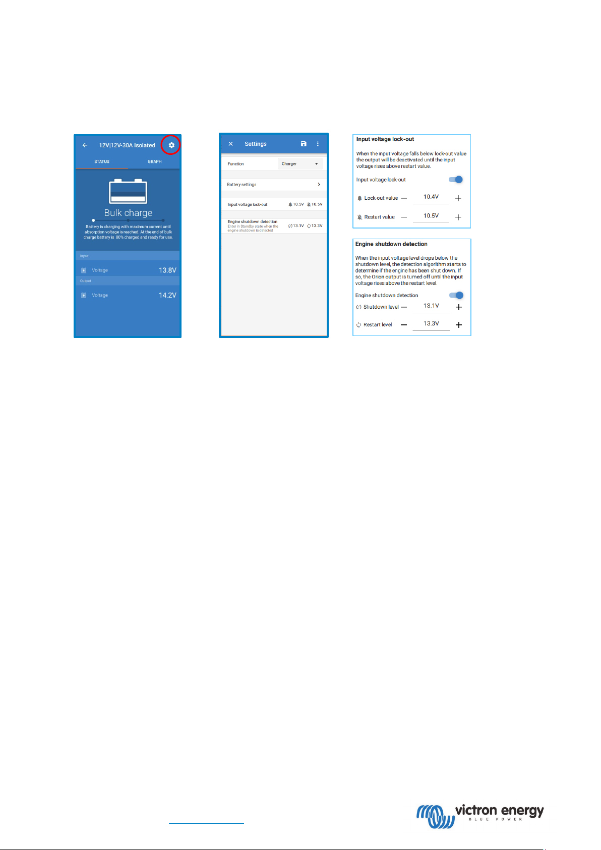
Open VictronConnect and press the Cog symbol to enter the settings.
(
The default setting (13.3V) is based on generic smart alternator setup. Most smart alternators will
generate 13.5V when the engine is running, and regular alternators will normally generate >14V. In an application with a
regular alternator the restart level can therefore be set to a higher value, e.g. 14V.
discharge of the starter battery.
The default setting is 13.1V. this creates a hysteresis between the restart level and prevents excess
Shutdown level range:
12|12; 12|24 models: 8 to 17V
24|12; 24|24 models: 16 to 35V
charging stops immediately. To determine this setting two criteria are important:
•
e.g. when the vehicle accelerates. This low voltage is allowed within the one-minute delay during
detection sequence 23”. If charging must remain active during this period, the lock-out level must at least be set
below the minimum alternator voltage.
be disabled on engine shutdown detection.
•
to the input current. The voltagedrop at Vin caused by Vcable must not trip the voltage lock-out. Therefore, the lockout value should be: Vlock-out = Valternator(min) – Vcable.
Example, calculating input cable voltage drop:
Distance between starter battery and charger: 5m. Valternator(min)= 12.5V. Recommended wire gauge: 16mm2.
Cable resistance: ~1.1mΩ/m @20°C, thus Rcable = 1.1mΩ x 10m (2x 5m) = 11mΩ
A 12|12-30A Smart Charger will draw about 35A from the input when running at full capacity, resulting in:
Vcable = 11mΩ x 35A = 385mV.
Vlock-out =< Valternator(min) – Vcable = 12.5V – 385mV ≈ 12.1V.
Input voltage lock-out is the minimum level at which charging is allowed, below this level
A smart alternator can (temporarily) operate at very low alternator voltage (<12.5V)
the “engine on
Note: If this low voltage period exceeds the one-minute timer charging will
As seen in “engine on detection sequence 12”, VIN is lowered by Vcable due
1)
.
The Restart value is normally set 0.1V higher than the Lock-out value to create hysteresis.
1) Cable connections, external fuses, temperature, etc. can influence cable resistance.
General phone: +31 (0)36 535 97 00 |E-mail: sales@victronenergy.com
 Loading...