

Page 1

ENGLISH
Ekrano GX Manual
Rev 01 - 07/2023
Page 2

Ekrano GX Manual
Table of Contents
1. Safety instructions ................................................................................................................... 1
2. Introduction ........................................................................................................................... 2
2.1. What is the Ekrano GX? .................................................................................................... 2
2.2. What's in the box? ........................................................................................................... 2
3. Installation ............................................................................................................................. 3
3.1. Ekrano GX Overview of connections ...................................................................................... 3
3.2. Mounting options ............................................................................................................ 4
3.3. Powering the Ekrano GX ................................................................................................... 5
3.4. Built-in 7-inch Touchscreen ................................................................................................. 6
3.5. Deactivating touch input control ........................................................................................... 7
3.6. Relay connections ........................................................................................................... 8
4. Connecting Victron products ...................................................................................................... 9
4.1. VE.Bus Multis/Quattros/Inverters .......................................................................................... 9
4.2. AC load monitoring ........................................................................................................ 10
4.3. Battery Monitor SmartShunt, BMV-700 series; and MPPTs with a VE.Direct port ................................. 10
4.3.1. DC load monitor mode .......................................................................................... 11
4.4. VE.Can Devices ........................................................................................................... 12
4.5. VE.Can Interfaces ......................................................................................................... 12
4.6. Inverter RS, Multi RS and MPPT RS .................................................................................... 12
4.7. BMV-600 series ............................................................................................................ 13
4.8. DC Link Box ................................................................................................................ 13
4.9. VE.Can Resistive Tank Sender Adapter ................................................................................ 13
4.10. Connecting a GX Tank 140 ............................................................................................. 13
4.11. Connecting hardwired Victron temperature sensors ................................................................. 14
5. Connecting supported non-Victron products ................................................................................. 16
5.1. Connecting a PV Inverter ................................................................................................. 16
5.2. Connecting a USB GPS .................................................................................................. 16
5.3. Connecting a NMEA 2000 GPS ......................................................................................... 17
5.4. Connecting a Fischer Panda Generator ................................................................................ 17
5.5. Connecting Tank Level Sensors to the GX Tank Inputs ............................................................... 18
5.6. Increasing the number of tank inputs by using multiple GX devices ................................................ 19
5.6.1. Introduction ...................................................................................................... 19
5.6.2. Requirements .................................................................................................... 20
5.6.3. Configuration step-by-step ..................................................................................... 20
5.7. Connecting third-party NMEA 2000 tank senders ..................................................................... 21
5.8. Mopeka Pro Check LPG and Water Bluetooth Sensors .............................................................. 22
5.8.1. Installation ........................................................................................................ 22
5.8.2. Configuration .................................................................................................... 23
5.8.3. Tank level monitoring ........................................................................................... 24
5.9. Wakespeed WS500 alternator regulator support ...................................................................... 25
5.9.1. Introduction ...................................................................................................... 25
5.9.2. Requirements .................................................................................................... 25
5.9.3. Wiring the WS500 to VE.Can .................................................................................. 25
5.9.4. Wiring Example .................................................................................................. 26
5.9.5. GX device user interface for WS500 .......................................................................... 27
5.9.6. WS500 data on the VRM Portal ............................................................................... 27
5.9.7. Troubleshooting & FAQ ......................................................................................... 28
5.10. Wireless Bluetooth Ruuvi temperature sensors ...................................................................... 29
5.11. Connecting IMT Solar Irradiance, Temperature and Wind Speed Sensors ....................................... 31
5.11.1. Data Visualisation - VRM ..................................................................................... 34
6. Internet connectivity ............................................................................................................... 35
6.1. Ethernet LAN port ......................................................................................................... 35
6.2. WiFi ......................................................................................................................... 36
6.3. GX LTE 4G ................................................................................................................. 36
6.4. Mobile (cellular) network using a 3G or 4G router ..................................................................... 36
6.5. USB tethering using a mobile phone .................................................................................... 37
6.6. Manual IP configuration ................................................................................................... 37
Page 3

Ekrano GX Manual
6.7. Connecting both Ethernet and WiFi (failover) .......................................................................... 37
6.8. Minimise internet traffic ................................................................................................... 37
6.9. More information about setting up an internet connection and VRM ................................................ 38
7. Accessing the GX device ......................................................................................................... 39
7.1. Using VictronConnect via Bluetooth ..................................................................................... 40
7.2. Accessing via built-in WiFi Access Point ............................................................................... 41
7.3. Accessing the Remote Console via local LAN/WiFi Network ........................................................ 42
7.3.1. Alternative methods to find the IP address for Remote Console .......................................... 42
7.4. Accessing via VRM ........................................................................................................ 43
7.5. The Remote Console menu .............................................................................................. 44
8. Configuration ....................................................................................................................... 45
8.1. Menu structure and configurable parameters .......................................................................... 45
8.2. Battery state of charge (SoC) ............................................................................................ 52
8.2.1. Which device should I use for SoC calculation? ............................................................. 52
8.2.2. The different solutions explained in detail .................................................................... 52
8.2.3. Notes on SoC .................................................................................................... 53
8.2.4. Selecting SoC source ........................................................................................... 53
8.2.5. Details on VE.Bus SOC ........................................................................................ 54
8.2.6. The System Status menu ...................................................................................... 54
8.3. Customise the logo on the Boat & Motorhome page .................................................................. 55
8.4. Temperature relay configuration ......................................................................................... 56
9. Firmware updates .................................................................................................................. 58
9.1. Changelog .................................................................................................................. 58
9.2. Via internet or with microSD-card/USB-stick ........................................................................... 58
9.2.1. Direct download from the internet ............................................................................. 58
9.2.2. MicroSD-card or USB-stick .................................................................................... 59
9.3. Revert to a previous firmware version .................................................................................. 59
9.3.1. Stored firmware backup feature ............................................................................... 60
9.3.2. Install a specific firmware version from SD/USB ............................................................ 61
10. VE.Bus Inverter/charger monitoring .......................................................................................... 62
10.1. Input current-limiter setting .............................................................................................. 62
10.2. Phase rotation warning .................................................................................................. 63
10.3. BMS connection lost alarm ............................................................................................. 63
10.4. Grid failure monitoring ................................................................................................... 65
10.5. Advanced menu .......................................................................................................... 65
10.6. Alarm status monitoring ................................................................................................. 66
10.7. VE.Bus alarm setup menu .............................................................................................. 66
10.8. Device menu .............................................................................................................. 66
11. DVCC - Distributed Voltage and Current Control ........................................................................... 67
11.1. Introduction and features ................................................................................................ 67
11.2. DVCC Requirements .................................................................................................... 68
11.3. DVCC effects on the charge algorithm ................................................................................ 69
11.3.1. DVCC effects when there is more than one Multi/Quattro connected ................................... 69
11.4. DVCC features for all systems .......................................................................................... 70
11.4.1. Limit charge current ........................................................................................... 70
11.4.2. Limit managed battery charge voltage ...................................................................... 70
11.4.3. Shared Voltage Sense (SVS) ................................................................................. 71
11.4.4. Shared Temperature Sense (STS) ........................................................................... 71
11.4.5. Shared Current Sense (SCS) ................................................................................. 72
11.4.6. Controlling BMS ................................................................................................ 72
11.5. DVCC features when using CAN-bus BMS battery .................................................................. 73
11.6. DVCC for systems with the ESS Assistant ............................................................................ 74
12. VRM Portal ......................................................................................................................... 75
12.1. VRM Portal introduction ................................................................................................. 75
12.2. Registering on VRM ..................................................................................................... 75
12.3. Datalogging to VRM ..................................................................................................... 75
12.4. Troubleshooting data logging ........................................................................................... 77
12.5. Analysing data offline, without VRM ................................................................................... 80
Page 4

Ekrano GX Manual
12.6. Remote Console on VRM - Setup ...................................................................................... 80
12.7. Remote Console on VRM - Troubleshooting ......................................................................... 81
13. Marine MFD integration by App ................................................................................................ 83
13.1. Introduction & requirements ............................................................................................ 83
13.2. Raymarine MFD Integration ............................................................................................ 84
13.2.1. Introduction ..................................................................................................... 84
13.2.2. Compatibility .................................................................................................... 84
13.2.3. Wiring ........................................................................................................... 84
13.2.4. GX device configuration ....................................................................................... 84
13.2.5. Configuring multiple battery measurements ................................................................ 85
13.2.6. Installation step-by-step ....................................................................................... 85
13.2.7. NMEA 2000 .................................................................................................... 86
13.2.8. Generic and supported PGNs ................................................................................ 86
13.2.9. Instancing requirements when using Raymarine ........................................................... 86
13.2.10. Before LightHouse 4.1.75 ................................................................................... 86
13.2.11. LightHouse 4.1.75 and newer ............................................................................... 87
13.3. Navico MFD Integration ................................................................................................. 87
13.3.1. Introduction ..................................................................................................... 87
13.3.2. Compatibility .................................................................................................... 87
13.3.3. Wiring ........................................................................................................... 88
13.3.4. GX device configuration ....................................................................................... 88
13.3.5. Configuring multiple battery measurements ................................................................ 88
13.3.6. Installation step-by-step ....................................................................................... 89
13.3.7. NMEA 2000 .................................................................................................... 89
13.3.8. Generic and supported PGNs ................................................................................ 89
13.3.9. Troubleshooting ................................................................................................ 89
13.4. Garmin MFD Integration ................................................................................................ 90
13.4.1. Introduction ..................................................................................................... 90
13.4.2. Compatibility .................................................................................................... 90
13.4.3. Wiring ........................................................................................................... 90
13.4.4. GX device configuration ....................................................................................... 90
13.4.5. Configuring multiple battery measurements ................................................................ 91
13.4.6. Installation step-by-step ....................................................................................... 91
13.4.7. NMEA 2000 .................................................................................................... 92
13.4.8. Generic and supported PGNs ................................................................................ 92
13.5. Furuno MFD Integration ................................................................................................. 92
13.5.1. Introduction ..................................................................................................... 92
13.5.2. Compatibility .................................................................................................... 92
13.5.3. Wiring ........................................................................................................... 93
13.5.4. Configuration ................................................................................................... 93
13.5.5. Configuring multiple battery measurements ................................................................ 94
13.5.6. NMEA 2000 .................................................................................................... 94
13.5.7. Generic and supported PGNs ................................................................................ 94
14. Marine MFD integration by NMEA 2000 ....................................................................................... 95
14.1. NMEA 2000 Introduction ................................................................................................ 95
14.2. Supported Devices / PGNs ............................................................................................. 95
14.3. NMEA 2000 Configuration .............................................................................................. 97
14.4. Configuring Multiple Tank Level Measurements (Raymarine) ...................................................... 97
14.5. Configuring Multiple Tank Level Measurements (Garmin) .......................................................... 98
14.6. Configuring Multiple Tank Level Measurements (Navico) ........................................................... 99
14.7. Configuring Multiple Tank Level Measurements (Furuno) .......................................................... 101
14.8. NMEA2000-out technical details ...................................................................................... 101
14.8.1. NMEA 2000 Glossary ........................................................................................ 101
14.8.2. NMEA 2000 Virtual-devices ................................................................................. 102
14.8.3. NMEA 2000 Classes and Functions ........................................................................ 102
14.8.4. NMEA 2000 Instances ....................................................................................... 102
14.8.5. NMEA 2000 Changing Instances ........................................................................... 103
14.8.6. PGN 60928 NAME Unique Identity Numbers ............................................................. 107
15. RV-C Support ..................................................................................................................... 108
15.1. RV-C Introduction ....................................................................................................... 108
15.2. Limitations ............................................................................................................... 108
15.3. Supported Devices ...................................................................................................... 108
15.4. RV-C Configuration ..................................................................................................... 109
15.4.1. Configuration of RV-C out devices .......................................................................... 110
Page 5

Ekrano GX Manual
15.5. Garnet SeeLevel II 709-RVC & Victron GX device support ........................................................ 111
15.5.1. Wiring the Garnet SeeLevel II 709-RVC tank level sensor to a GX device ............................ 111
15.5.2. Installation and configuration ................................................................................ 111
16. Digital Inputs ..................................................................................................................... 112
16.1. Configuration ............................................................................................................ 112
16.2. Read-out of digital inputs via Modbus TCP .......................................................................... 113
17. GX - Generator auto start/stop ................................................................................................ 114
17.1. Generator auto start/stop introduction ................................................................................ 114
17.2. Wiring ..................................................................................................................... 114
17.3. Enabling the start/stop function ....................................................................................... 114
17.4. General start/stop menu ............................................................................................... 115
17.5. Settings menu ........................................................................................................... 115
17.6. Conditions: User definable parameters that trigger an automatic generator start/stop ......................... 116
17.6.1. Generator stop when AC-input becomes available after a mains failure ............................... 116
17.6.2. Relays triggered by Battery SoC ............................................................................ 116
17.6.3. Relays triggered by Battery Current ........................................................................ 117
17.6.4. Relays triggered by Battery Voltage ........................................................................ 117
17.6.5. Relays triggered by AC load ................................................................................. 117
17.6.6. Relays triggered by Inverter High temperature ............................................................ 118
17.6.7. Relays triggered by Inverter overload ...................................................................... 118
17.6.8. Automatic periodic 'Test run' ................................................................................. 118
17.6.9. Manual Start Feature ......................................................................................... 118
17.6.10. Quiet hours ................................................................................................... 119
17.7. Troubleshooting ......................................................................................................... 120
18. Reset to factory defaults procedure ......................................................................................... 121
19. Troubleshooting ................................................................................................................. 122
19.1. Error Codes .............................................................................................................. 122
19.2. FAQ ....................................................................................................................... 123
19.2.1. Q1: I cannot switch my Multi/Quattro system on or off ................................................... 123
19.2.2. Q2: Do I need a BMV to see proper battery state of charge? ........................................... 123
19.2.3. Q3: I have no internet, where can I insert a SIM card? ................................................... 123
19.2.4. Q4: Can I connect both a GX Device and a VGR2/VER to a Multi/Inverter/Quattro? ................. 123
19.2.5. Q5: Can I connect multiple Ekrano GX to a Multi/Inverter/Quattro? .................................... 123
19.2.6. Q6: I see incorrect current (amps) or power readings on my EGX ...................................... 124
19.2.7. Q7: There is a menu entry named "Multi" instead of the VE.Bus product name ...................... 124
19.2.8. Q8: There is a menu entry named "Multi", while there is no Inverter, Multi or Quattro connected .. 124
19.2.9. Q9: When I type the IP address of the Ekrano GX into my browser, I see a web page
mentioning Hiawatha? ................................................................................................ 124
19.2.10. Q10: I have multiple Solar chargers MPPT 150/70 running in parallel. From which one will I
see the relay status in the EGX menu? ............................................................................. 125
19.2.11. Q11: How long should an automatic update take? ...................................................... 125
19.2.12. Q12: I have a VGR with IO Extender, how can I replace this with a Ekrano GX? ................... 125
19.2.13. Q13: Can I use Remote VEConfigure, as I was doing with the VGR2? ............................... 125
19.2.14. Q14: The Blue Power Panel could be powered through the VE.Net network, can I also do that
with a Ekrano GX? ..................................................................................................... 125
19.2.15. Q15: What type of networking is used by the Ekrano GX (TCP and UDP ports)? ................... 125
19.2.16. Q16: What is the functionality behind the menu item Remote support (SSH) in the Ethernet
menu? ................................................................................................................... 126
19.2.17. Q17: I don’t see support for VE.Net products in the list, is that still coming? ......................... 126
19.2.18. Q18: What is the data usage of the Ekrano GX? ........................................................ 126
19.2.19. Q19: How many AC Current Sensors can I connect in one VE.Bus system? ........................ 126
19.2.20. Q20: Issues with Multi not starting when EGX is connected / Caution when powering the EGX
from the AC-out terminal of a VE.Bus Inverter, Multi or Quattro ................................................. 126
19.2.21. Q21: I love Linux, programming, Victron and the EGX. Can I do more? .............................. 127
19.2.22. Q22: How do I change the logo ............................................................................ 127
19.2.23. Q23: Multi restarts all the time (after every 10sec) ...................................................... 127
19.2.24. Q24: What is Error #42? .................................................................................... 127
19.2.25. Q25: My GX device reboots itself. What is causing this behavior? .................................... 127
19.2.26. GPL Note .................................................................................................... 128
20. Technical specifications ........................................................................................................ 129
Page 6

Ekrano GX Manual
20.1. Technical specifications ................................................................................................ 129
21. Appendix .......................................................................................................................... 131
21.1. RV-C ...................................................................................................................... 131
21.1.1. Supported DGNs .............................................................................................. 131
21.1.2. RV-C out ....................................................................................................... 131
21.1.3. DGN 60928 Unique Identity Numbers ...................................................................... 137
21.1.4. RV-C in ......................................................................................................... 137
21.1.5. Device Classes ............................................................................................... 137
21.1.6. Instance Translation .......................................................................................... 138
21.1.7. RV-C Fault and Error Handling .............................................................................. 138
21.1.8. RV-C Device Priority .......................................................................................... 139
21.2. Ekrano GX Dimensions ................................................................................................ 140
21.3. Ekrano GX cut-out template ........................................................................................... 141
Page 7

Ekrano GX Manual
1. Safety instructions
SAVE THESE INSTRUCTIONS – This manual contains important instructions that shall be followed
during installation, setup, operation and maintenance.
• Please read this manual carefully before the product is installed and put into use
• Make sure you have the latest version of the manual. The most recent version can be downloaded from the product page.
• Install the product in a heatproof environment. Ensure therefore that there are no chemicals, plastic parts, curtains or other
textiles, etc. in the immediate vicinity of the equipment.
• Ensure that the equipment is used under the correct operating conditions. Never operate it in a wet environment.
• Never use the product at sites where gas or dust explosions could occur
• This device is not to be used by persons (including children) with reduced physical, sensory or mental capabilities, or lack of
experience and knowledge, unless they have been given supervision or instruction.
Page 1 Safety instructions
Page 8

Ekrano GX Manual
2. Introduction
2.1. What is the Ekrano GX?
The Ekrano GX (EGX) is the newest addition to the GX product family. It is an all-in-one device with built-in 7-inch touchscreen
display and extensive connectivity. The Ekrano GX is the successor of the Color Control GX.
GX products are Victron's state-of-the-art monitoring and control solution that run our Venus OS operating system. It sits at the
heart of your energy installation. All the other system-components such as inverter/chargers, solar chargers, and batteries are
connected to it. The EGX ensures that they all work in harmony.
To monitor and control your system, you can simply access it remotely via our Victron Remote Management (VRM) portal from
anywhere in the world using an internet connection. Or access it directly, using the integrated touchscreen, a web browser, a
Multi-Functional Display (MFD) [83] or our VictronConnect app.
The Remote Console [39] serves as the primary control center for monitoring, controlling and managing your system.
The EGX also provides VRM: Remote firmware updates and allows settings to be changed remotely.
Note that all the information in this manual refers to the latest software. You can check your device has the latest version in
the firmware menu (see the Firmware updates [58] chapter) when the GX device is connected to the internet. For installations
without internet, you can find the latest version in Victron Professional.
2.2. What's in the box?
Ekrano GX
Power cable with 3.15A inline fuse and M8 terminal eyes for battery or
DC busbar-attachment
VE.Can terminators (2 pcs)
Terminal blocks with mounting screws for: Relays (2 pcs), Power
Connector
IO terminal block with quick release clamps
Mounting material:
Steel bracket for panel mount incl. rods, wingnuts and washers
Springs for panel blind hole mount incl. screws and washers
Page 2 Introduction
Page 9

Ekrano GX Manual
3. Installation
3.1. Ekrano GX Overview of connections
Communication ports IO Other
3x VE.Direct 2x Digital Inputs MicroSD Card Slot (max. 32GB)
2x VE.Can 3x Resistive Tank Level Inputs Recessed Button for Touch
Control
1x VE.Bus 2x Temperature Sensor Inputs Power Supply Port (8 - 70VDC)
Ethernet
WiFi 2.4GHz (802.11 b/g/n)
Bluetooth Smart
2x USB Host Ports (current limit:
1.5A@5V shared)
2x Programmable Relay (NO, COM, NC
- current limit: DC up to 30VDC: 3A / AC
125VAC: 1A))
7-inch TFT LCD Touchscreen
(1024x600 pixels)
Page 3 Installation
Page 10

Ekrano GX Manual
3.2. Mounting options
The Ekrano GX comes with a solid steel bracket, two rods and wingnuts for mounting from the back and an option to mount from
the front only, using the attached springs.
Mounting from the back
Mount the Ekrano GX from the back when it is easily accessible.
1. Prepare the cut-out as per the cut-out template from the appendix.
2. Screw the supplied M5 studs with the short threaded end into the rear threads.
3. Place the EGX in the cut-out and mount the steel bracket with the wing nuts provided.
4. Tighten the wing nuts. When done correctly, this squeezes the seal to the surface around the cut-out, making it watertight.
Mounting from the the front
2
Mount the Ekrano GX from the front if it is not accessible via the back.
1. Prepare the cut-out as per the cut-out template from the appendix.
4
2. Mount the supplied springs using the two screws with washers.
3. Make all necessary cable connections.
4. Push the springs carefully back and hold them with your fingers while inserting the EGX into the cut-out. Then release the
springs. They will snap back once the EGX is fully inserted and hold the device in place. Be careful as those springs are
strong and it hurts really bad when they accidentally snap onto your fingers.
Mounting position
Even though the Ekrano GX is watertight from the front (when using the steel bracket) and has a bright backlight, do not to mount
it in direct sunlight to prevent overheating and to gain better readability. Mount it horizontally. Portrait mode or automatic rotation is
not supported.
Page 4 Installation
Page 11

Ekrano GX Manual
3.3. Powering the Ekrano GX
The device is powered by using the Power in V+ connector. It accepts 8 to 70V DC. The device will not power itself from any of
the other connections (eg network). The supplied DC power cable includes an inline 3.15A slow blow fuse.
When the EGX is used in an installation with a VE.Bus BMS, connect the Power in V+ on the EGX to the terminal labelled 'Load
disconnect' on the VE.Bus BMS. Connect both negative leads to the negative stub of a common battery.
A cautionary word about powering from the AC-out terminal of a VE.Bus Inverter, Multi or Quattro:
If you power the EGX from an AC adaptor connected to the AC-out port of any VE.Bus product (Inverter, Multi or Quattro), then
a deadlock will occur after the VE.Bus products are powered-down for any reason (after any operational fault or during a black
start). The VE.Bus devices will not boot-up until the EGX has power …but the EGX will not boot-up until it has power. This
deadlock can be rectified by briefly unplugging the EGX VE.Bus cable at which point you will observe the VE.Bus products will
immediately begin to boot-up.
Or a modification can be done to the RJ45 cabling. See FAQ Q20 [126] for more information about this.
Note that both with or without above modification, powering the monitoring equipment with the AC-out of an inverter/charger (of
course) has the disadvantage that all monitoring is shut down when there is a problem that causes the inverter/charger to shut
down. Examples are inverter overload, high temperature or low battery voltage. It is therefore recommended to power the GX
device from the battery.
Isolation
Because the EGX is connected to many different products, please ensure that proper care is taken with isolation to prevent
ground loops. In 99% of installations this will not be a problem.
• VE.Bus ports are isolated
• VE.Direct ports are isolated
• VE.Can port 1 is galvanically isolated, VE.Can port 2 is non-isolated
• USB ports are not isolated. Connecting a WiFi Dongle or GPS Dongle will not create a problem as it is not connected
to another power supply. Even though there will be ground loop when you mount a separately-powered USB hub, during
extensive testing we have not found that it caused any issues.
• The Ethernet port is isolated, except for the shield: use unshielded UTP cables for the Ethernet network.
Extending USB ports by use of a self-powered USB hub
Although the number of USB ports can be extended by using a hub, there is a limit to the amount of power that the onboard USB
port can provide. When extending the number of USB ports, we recommend you always use powered USB hubs. And to minimize
the chance of issues, be sure to use good-quality USB hubs. As Victron also offers a VE.Direct to USB adapter, you can use this
arrangement to increase the number of VE.Direct devices you can connect to your system, please see this document for the limit
of how many devices can be attached to various different GX devices.
Page 5 Installation
Page 12

Ekrano GX Manual
3.4. Built-in 7-inch Touchscreen
The built-in 7-inch touchscreen display provides an instant overview of your system and allows you to adjust settings on the fly.
The super slim and waterproof design and easy installation offers a lot of flexibility in creating a clear and clean dashboard.
No configuration is required. When the screen is connected, the device will automatically display the GX overview and menu
controls.
Display options are available in the Settings → Display & Language menu. You can set a time before the display turns off, or
enable adaptive brightness.
The screen is controlled by a finger tip. You can swipe to scroll up and down through the menus, and tap to make selections. Text
and number input is entered via an onscreen keyboard.
Page 6 Installation
Page 13

Ekrano GX Manual
3.5. Deactivating touch input control
In order to restrict access to the GX system, it is possible to disable touch input control for the touchscreen. This allows the
Ekrano GX to be mounted where it is visible by the operator of the system; and at the same time prevent them from using that to
elevate their access level.
Note that this feature only disables touch/mouse control. On the Remote Console you are still able to control the device with
keyboard input.
There are three ways to disable the touch function of the display:
1. Using the recessed button on the back
2. Using a momentary-push button wired to one of the digital inputs
3. By using an external USB keyboard connected to the Ekrano GX; The touch function can then be toggled on and off by
pressing the Pause/Break key.
If you want to use this function, make sure that the USB ports and the USB keyboard are not accessible.
Deactivating touch input control via the recessed button on the back of the Ekrano GX
1. Take a pointed object (e.g. pen or paperclip) and press the button once
Touch input is now off. Entries are no longer possible. The display switches off after the time set under Display off time (see
menu Display & Language). Touching the screen activates the last page set.
2. Pressing the button again activates the touch function
Deactivating touch input control using a momentary-push button
1. Go to Settings → IO → Digital inputs → Digital input [number of the digital input]
2. Scroll down the submenu until you see the Touch input control option
3. Press the spacebar or click/tap to enable Touch input control
4. Wire a momentary-push button between the appropriate top and bottom pins of the associated digital input
Pushing the button once will activate (disable) touch. Touch entries are no longer possible. The display switches off after the
time set under Display off time (see menu Display & Language). Touching the screen activates the last page set. Pushing the
button again will deactivate (enable) touch. Note that this pulls the gpio pin to ground. Do not apply voltage to the gpio pins.
Deactivating touch input control using an external USB keyboard
1. Connect an external USB keyboard to one of the USB ports on the Ekrano GX
2. Press the Pause/Break key to toggle touch input control on/off.
For keyboards without Pause/Break key use one of the substitute key combinations mentioned in this Wikipedia article.
Page 7 Installation
Page 14
Ekrano GX Manual
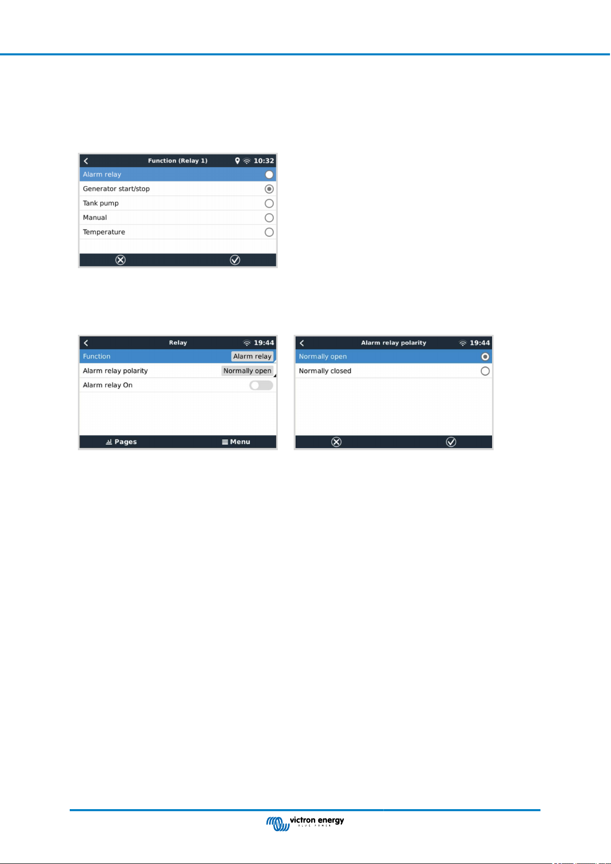
3.6. Relay connections
The Ekrano GX has potential-free Normally Open (NO) and Normally Closed (NC) relay functionality. The function of the relays
can be set via the GX menu, Settings → Relay → Function.
Relay 1 is of particular importance because, in addition to manual and temperature [56]-related triggering (also applies to relay
2), it can also be used as an alarm [45], generator start/stop [114] or tank pump [45] relay.
If the relay function is configured as an Alarm relay, it is possible to reverse the polarity of the relay via an additional menu. The
default setting is Normally open. Please note that reversing the polarity to Normally closed will result in a slightly higher current
consumption of the GX device.
Observe the voltage and current limits of the relays, which are: DC up to 30VDC: 3A - AC: 1A, 125VAC
Page 8 Installation
Page 15

Ekrano GX Manual
4. Connecting Victron products
4.1. VE.Bus Multis/Quattros/Inverters
In order to keep this document short we are going to refer to all Multis, Quattros and Inverters as VE.Bus products.
The earliest version of VE.Bus devices that can be connected using the Products: Product_Acronym is 19xx111, where the first 2
digits represent the microprocessor and the last 3 digits represent the VE.Bus firmware version.
VE.Bus device microprocessor GX device support
18xxxxxx No
19xx111 Yes
20xx111 Yes
26xxxxx Yes
27xxxxx Yes
Note that for Multis, Quattros and EasySolars, it is not possible to use the Remote On/Off (header on the VE.Bus control PCB) in
combination with a EGX. There should be a wire between the left and middle terminal, as it is when shipped from the factory. In
case a wired switch that disables the system is required, use the Safety Switch Assistant instead.
This limitation does not apply to the next generation of VE.Bus inverter/chargers: when using a MultiPlus-II, Quattro-II or
EasySolar-II, the Remote on/off terminal header *can* be used in combination with Ekrano GX.
Before connecting any VE.Bus product, be very careful not to confuse the GX device VE.Bus ports
with the Ethernet or VE.Can/BMS-Can port!
Single VE.Bus products
To connect a single VE.Bus product, connect it to one of the VE.Bus sockets on the back of the EGX. Both sockets are identical,
use either one. Use a standard RJ45 UTP cable, see our pricelist.
Parallel, split- and three-phase VE.Bus systems
To connect multiple VE.Bus products, configured as a parallel, split-phase or three-phase VE.Bus system, connect either the first
or the last VE.Bus product in the chain to either one of the VE.Bus sockets on the back of the EGX. Use a standard RJ45 UTP
cable, see our pricelist.
VE.Bus systems with Lithium batteries and a VE.Bus BMS
• The following only applies to the VE.Bus BMS v1, not to be confused with its successor VE.Bus BMS V2.
• Connect the EGX to the socket labelled ‘MultiPlus/Quattro’, or to one of the Multis/Quattros in the system. Do not connect it to
the Remote panel socket on the VE.Bus BMS.
• Note that it will not be possible to control the On/Off/Charger Only switch. This option is automatically disabled in the EGX
menu when a VE.Bus BMS is used. The only way to control a Multi or Quattro when used with a VE.Bus BMS is to add a Digital
Multi Control to the system. Setting the input current limit is possible in systems with a VE.Bus BMS.
• Combining MultiPlus/Quattro with a VE.Bus BMS and a Digital Multi Control is possible. Simply connect the Digital Multi Control
to the RJ-45 socket on the VE.Bus BMS labelled Remote panel.
• To allow auto-power-down in the EGX in case of a low battery, make sure the EGX is powered via the VE.Bus BMS: connect
Power in V+ on the EGX to Load disconnect on the VE.Bus BMS. And connect both negative leads to the negative stub of a
common Battery.
Combining the EGX with a Digital Multi Control
It is possible to connect both a EGX and a Digital Multi Control to a VE.Bus system. The ability to switch the product On, Off or set
it to Charger Only via the EGX will be disabled. The same applies to the input current limit: when there is a Digital Multi Control in
the system, the input current limit which is set at that control panel will be the master-setting, and changing it on the EGX will not
be possible.
Connecting multiple VE.Bus systems to a single EGX
Page 9 Connecting Victron products
Page 16

Ekrano GX Manual
Only one VE.Bus system can be connected to the VE.Bus ports on the back of the EGX. The professional way to to monitor more
systems is to add a second EGX
If you do require to connect more than one system to the same EGX, use an MK3-USB. Functionality will be limited:
• Only the system connected to the built-in VE.Bus ports is used to generate the data on the Overview pages.
• All connected systems will be visible on the Device List.
• All connected systems will be taken into account for Energy consumption and distribution calculations (kWh graphs on VRM).
• Only the system connected to the built-in VE.Bus ports is used for the Generator start/stop logic.
• Only the Multi/Quattro (which can be a single device, or multiple together configured for three-/split-phase as well as parallel)
connected to the VE.Bus port will be controlled via DVCC. Additional systems, connected to the GX device using an MK3-USB,
are not controlled by DVCC and will charge and discharge according to the configuration made in those units.
• In case of an ESS system, only the system connected to the built-in VE.Bus ports is used in the ESS mechanisms. The other
one is displayed in the Device List only.
Alternatively the VE.Bus to VE.Can interface (ASS030520105) can be used. Add one for each additional system. Note that we
advise against it; this interface is a deprecated product. Make sure that the VE.Can network is terminated and powered. For
powering the VE.Can network, see Q17 in our data communication whitepaper.
Additional features provided by a GX device to VE.Bus products
An internet connected GX device allows for remote configuration via the VRM Portal. Please read the Remote VE.Configure
manual for more information, system requirements and specific steps to access this feature.
The internet connected GX device also allows remotely updating the firmware of VE.Bus products. For details see the Remote
VE.Bus firmware updates manual.
4.2. AC load monitoring
All energy meter types can be assigned the AC meter role. This is done in Settings → Energy meters → [your_energy_meter]
→ Role menu where you choose between Grid, PV Inverter, Generator and AC meter. With AC meter selected, the load will be
shown in the Device list and on VRM in the advanced widgets.
Please note that such metered loads are not used in any calculations, just monitoring.
4.3. Battery Monitor SmartShunt, BMV-700 series; and MPPTs with a VE.Direct
port
Direct connection via a VE.Direct cable is limited to the number of VE.Direct ports on the device (see Overview of
Connections [3]). There are two types of VE.Direct cables available:
1. Straight VE.Direct cables, ASS030530xxx
2. VE.Direct cables with an angled connector on one end. These are designed to minimise the required depth behind a panel,
ASS030531xxx
VE.Direct cables have a maximum length of 10 metres. It is not possible to extend them. If longer lengths are required, use a
VE.Direct to USB interface with an active USB extension cable.
It is also possible to use the VE.Direct to VE.Can interface, but note that this only works for BMV-700 and BMV-702. Not for the
BMV-712, MPPT solar chargers and Inverters with a VE.Direct port. See next paragraph for more information on that VE.Can
interface.
Connecting more VE.Direct devices to your Ekrano GX than number of VE.Direct Ports
Page 10 Connecting Victron products
Page 17

Ekrano GX Manual
First of all, note that the maximum of VE.Direct devices that can be connected is GX device specific, and constrained by the CPU
power. It may also be reduced for very complex systems, such as many AC PV inverters or synchronised inverter chargers, etc.
So always allow some additional headroom in the design. How they are connected, whether via VE.Direct, via USB or USB hub,
does not change this maximum. See the Victron GX product range for the maximum limit on all GX devices.
For the Ekrano GX, this limit is 25.
Options to connect more VE.Direct products than available VE.Direct ports:
1. Use the VE.Direct to USB interface. The EGX has built-in USB ports. Use a USB-hub when additional USB ports are required.
2. (Only!) the BMV-700 and BMV-702 can also be connected using the VE.Direct to VE.Can interface (deprecated). Note that
the BMV-712, MPPTs and VE.Direct Inverters cannot be connected using this CAN-bus interface as it does not translate
their data into CAN-bus messages. When using the VE.Direct to VE.Can interface, make sure that the VE.Can network is
terminated, and also powered. For powering the VE.Can network, see Q17 in our data communication whitepaper. Lastly,
note that this CAN-bus interface is deprecated.
Notes about older VE.Direct MPPTs
• An MPPT 70/15 needs to be from year/week 1308 or later. Earlier 70/15s are not compatible with the EGX , and unfortunately
upgrading the MPPT firmware will not help. To find the year/week number of your model, look for the serial number which is
printed on a label on its back. For example number HQ1309DER4F means 2013, week 09.
4.3.1. DC load monitor mode
If you wish to use a SmartShunt or BMV-712 to monitor individual DC circuits, rather than as a whole-of-system battery monitor,
you can change the Monitor mode setting from Battery Monitor to DC Energy Meter in VictronConnect.
If DC meter is selected, you can then select the following types (also in VictronConnect):
Solar charger, Wind charger, Shaft generator, Alternator, Fuel cell, Water generator, DC-DC charger, AC charger, Generic source,
Generic load, Electric drive, Fridge, Water pump, Bilge pump, DC system, Inverter, Water heater
Once connected to the Ekrano GX, the type and the amps and power of the DC load is shown in the user interfaces and available
on the VRM Portal.
When configured as type “DC System”, the EGX does more than just recording and visualisation:
1. The power shown in the DC system box is the sum of power reported by all SmartShunts configured as such. Allowing
multiple meters is done to accommodate for example a catamaran, so you can measure the DC Systems on Port hull and on
Starboard hull.
2. The DC system current is being compensated for when setting DVCC charge current limits to Multis, Quattros and Solar
Chargers. For example when a load of 50A is being measured, and CCL by the battery is 25A, the limit given to the Multis &
Solar Chargers is 75A. An improvement for systems with significant DC loads such as Yachts, Coaches and RVs.
Notes and limitations:
• This feature is available for SmartShunts and BMV-712. Not for BMV-700 or BMV-702.
• Setting the meter mode is done with VictronConnect, in the BMV/SmartShunt itself. For details see the BMV-712 or SmartShunt
product manual on the Battery Monitor product page.
• The NMEA2000-out feature does not support these new types, for example when using a SmartShunt to measure output of an
alternator, that data is not made available on NMEA 2000.
Page 11 Connecting Victron products
Page 18

Ekrano GX Manual
4.4. VE.Can Devices
To connect a product with a VE.Can port, use a standard RJ45 UTP cable (available with straight and elbow connectors).
Don't forget to terminate the VE.Can network at both ends using a VE.Can terminator. A bag with two terminators is supplied with
each VE.Can product. They are also available separately.
Other notes:
1. In order to work with the EGX, an MPPT 150/70 must be running firmware v2.00 or newer.
2. You can combine a Skylla-i control panel with a EGX.
3. You can combine a Ion Control panel with a EGX.
4. All VE.Can devices power the VE.Can network, so it won't be necessary to power the VE.Can network separately in these
circumstances. All the protocol converters, for example the VE.Bus to VE.Can interface and the BMV to VE.Can interface, do
not power the VE.Can network.
The following VE.Can products also support VictronConnect-Remote (VC-R) – Configuration and monitoring via VRM. Please
read the VictronConnect manual for further details.
VE.Can product VC-R Remarks
Lynx Shunt VE.Can Yes -
Lynx Smart BMS Yes -
Inverter RS, Multi RS and MPPT RS
Blue/Smart Solar VE.Can MPPTs
Skylla-i and Skylla-IP44/-IP65 Yes Requires firmware v1.11
[1]
All VE.Can solar chargers except the very old (big rectangular case with display) BlueSolar MPPT VE.Can 150/70 and
150/85
[1]
Yes They also have VE.Direct but must be connected via VE.Can for
VC-R
Yes Tr and MC4 models
4.5. VE.Can Interfaces
The Ekrano GX has two fully functional VE.Can ports. They are independent from a data and connected device perspective. One
is labelled VE.Can 1 and is galvanically isolated, the other is labeled VE.Can 2 and is non-isolated. These each correspond to the
VE.Can ports listed in the Services menu (Settings → Services) of the Remote Console.
VE.Can is intended to be used for Victron (and Victron compatible) VE.Can products, such as the VE.Can MPPTs, Skylla-IP65,
Lynx Shunt VE.Can and Lynx Smart BMS. You can string these VE.Can 250 kbit/s devices together along this bus. It must be
terminated at both ends with the included VE.Can terminators.
You can set the VE.Can port from 250 kbit/s to be 500 kbit/s (or one of several other CANbus speeds for other CANbus
applications).
By default; VE.Can is set to 250 kbit/s.
Other types of Batteries and BMS may claim compatibility with BMS-Can or VE.Can, but if they are not on the battery
compatibility list, then they have not been tested and confirmed to work by Victron.
One extra element of possible confusion is that there are some BMS products on the market that use a CANbus-BMS profile
at 250 kbit/s. These BMS products can only be connected to the VE.Can port, and it must also be set to match this (VE.Can &
CAN-bus BMS (250 kbit/s)) in the services menu for the VE.Can port. They can be used in the same cable daisy chain as other
Victron VE.Can devices.
4.6. Inverter RS, Multi RS and MPPT RS
The Inverter RS, Inverter RS Solar and Multi RS have both VE.Direct and VE.Can interfaces. For these specific products, it
is only possible to connect a GX device via the VE.Can interface. It is not possible to connect a GX device via the VE.Direct
interface.
The VE.Direct interface on these specific products is only used for connection of a VE.Direct to USB adapter for programming.
This restriction does not apply to the MPPT RS, which can be connected to a GX device via either VE.Direct or VE.Can.
Page 12 Connecting Victron products
Page 19

Ekrano GX Manual
4.7. BMV-600 series
• Connect the BMV-600 using the VE.Direct to BMV-60xS cable. (ASS0305322xx).
4.8. DC Link Box
• Connect the DC Link Box with the supplied RJ12 cable. Then connect the BMV-700 to the EGX.
4.9. VE.Can Resistive Tank Sender Adapter
See the VE.Can resistive tank sender adapter product page for details about the adapter.
• To connect a product with a VE.Can port, use a standard RJ45 UTP cable
• Don't forget to terminate the VE.Can network on both ends using a VE.Can terminator. A bag with two terminators is supplied
with each VE.Can product. They are also available separately (ASS030700000). (Available with straight or elbow connectors).
• Make sure that the CAN-bus is powered, see the Power chapter in the Tank Sender Adapter manual for details.
4.10. Connecting a GX Tank 140
The GX Tank 140 is an accessory for our range of GX system monitoring products.
It takes readings from up to four tank level sensors.
Tank levels can be read-out locally in the system, as well remotely through our VRM Portal.
The GX Tank 140 is compatible with current senders (4 to 20mA) as well as voltage senders (0 to 10V). The connection to the GX
device is via USB, which is also how the GX Tank is powered: no additional power wires required.
To make wiring the tank sender as simple as possible, two of the four inputs provide a 24V power supply, to power the sender.
Using the other two channels requires an external power supply, and there is a power in terminal together with fused outputs to
facilitate that.
Upper and lower limits are configurable, to allow using senders that provide only part of the scale, for example 0 to 5V.
For marine applications, the GX device can transmit these tank levels on the NMEA 2000 network to be picked up by other
displays such as an MFD.
The GX Tank 140 product page links to the complete documentation of this product.
Page 13 Connecting Victron products
Page 20

Ekrano GX Manual
4.11. Connecting hardwired Victron temperature sensors
See the Connection Overview [3] for the location and number of temperature sensor inputs.
They can be used to measure & monitor all kinds of temperature inputs. The measuring temperature range of the temperature
inputs is -40°C to +70°C.
Temperature senders are not included. The required sensor is ASS000001000 - Temperature sensor Quattro, MultiPlus and GX
Device. Note that this is different from the BMV temperature accessory. The BMV temperature sensor accessory cannot be used
on the temperature inputs.
They are not required to be connected to the battery (though they appear like a battery lug).
To physically attach the temperature probes requires a ferrule or exposed copper end of at least 10 mm+ to be inserted into the
removable terminal block connector. Once correctly attached, you must push in the orange tab if you wish to remove the secured
wire. Sensors are connected with the red wire to the top of the connector, and the black wire to the bottom.
ASS000001000 - Temperature sensor Quattro,
Sensors are enabled (and disabled) in the Settings → I/O → Analog inputs menu of the GX device settings.
Once enabled, temperature sensor data is visible in the device list, and also logged to VRM.
Selecting the temperature sensor from the device list menu then allows you to set the temperature type setting to either Battery,
Fridge or Generic. It is also possible to set a custom name in the Device menu.
MultiPlus and GX Device
It is possible to adjust the temperature offset and scale, however for now this feature is limited to users with 'superuser'
permission level.
Page 14 Connecting Victron products
Page 21

Ekrano GX Manual
Page 15 Connecting Victron products
Page 22

Ekrano GX Manual
5. Connecting supported non-Victron products
5.1. Connecting a PV Inverter
Measuring the output of a PV Inverter will provide the user with an overview of both actual power balance and the energy
distribution. Note that these measurements are only used to display information. They are not needed nor used by the installation
for its performance. Besides monitoring, the GX device can also curtail some types and brands of PV Inverters, ie. reduce their
output power. This is used, and required, for the ESS Zero or limited feed-in feature.
Direct connections
Type Zero feed-in Details
Fronius Yes LAN Connection, see GX - GX - Fronius
manual
SMA No LAN Connection, see GX - GX - SMA manual
SolarEdge No LAN Connection, see GX - SolarEdge manual
ABB Yes LAN Connection, see GX - ABB manual
Using a meter
For PV Inverters that cannot be interfaced digitally, a meter can be used:
Type Zero feed-in Details
AC Current
Sensor
Energy Meter
Wireless AC
sensors
No Connected to inverter/charger analog input.
Lowest cost - least accurate. Energy Meter
No Wired to the EGX, or connected wirelessly
using our Zigbee to USB/RS485 converters.
See the Energy Meters start page
No See the Wireless AC Sensor manual -
Discontinued product
5.2. Connecting a USB GPS
Use a GPS to remotely, on the VRM Portal, track vehicles or boats. Also its possible to configure a Geofence, which will
automatically send an alarm when the system leaves a designated area. And gps-tracks.kml files can be downloaded to open
them e.g. in Navlink and Google Earth.
Victron does not sell USB-GPS modules, but the EGX support third-party GPS modules which use the NMEA0183 command-set
- almost all do. It can communicate at both 4800 and 38400 baud rates. Plug the unit into either of the USB sockets. Connection
may take a few minutes, but the EGX will automatically recognize the GPS. The unit's location will automatically be sent to the
VRM online portal and its position is shown on the map.
The EGX has been tested for compatibility with:
• Globalsat BU353-W SiRF STAR III 4800 baud
• Globalsat ND100 SiRF STAR III 38400 baud
• Globalsat BU353S4 SiRF STAR IV 4800 baud
• Globalsat MR350 + BR305US SiRF STAR III 4800 baud
Page 16
Connecting supported non-Victron
products
Page 23

Ekrano GX Manual
5.3. Connecting a NMEA 2000 GPS
Instead of a USB GPS, a NMEA 2000 GPS can be used for remote vehicle or boat tracking in the VRM portal.
The third party NMEA 2000 GPS sender must meet the following requirements:
• The NMEA 2000 device class must be 60, Navigation.
• The NMEA 2000 device function must be 145, Ownship Position (GNSS).
• Position (latitude, longtitude) must be transmitted in PGN 129025.
• Height, which is optional, must be transmitted in PGN 129029.
• Course and speed (both optional), must be transmitted in PGN 129026.
Most NMEA 2000 GPS-es are expected to work. Compatibility has been tested with:
• Garmin GPS 19X NMEA 2000
To connect a NMEA 2000 network to the VE.Can port on the GX device, which both have a different style connector, there are two
solutions:
1. The VE.Can to NMEA 2000 cable. Which by either inserting or leaving out the fuse allows to either power the NMEA 2000
network with Victron equipment, or not. Take note of below warning.
2. The 3802 VE.Can Adapter by OSUKL. Its advantage is that it lends itself well to connecting a single NMEA 2000 device such
as a tank sender into a VE.Can network. It's also able to power a lower voltage NMEA 2000 network directly from a 48V
Victron system.
Warning and solution for 24V and 48V systems
Whilst all Victron components accept up to 70V input on their CAN-bus connections, some NMEA 2000 equipment does not. They
require a 12V powered NMEA 2000 connection, and sometimes work up to 30 or 36V. Make sure to check the datasheet of all
used NMEA 2000 equipment. In case the system contains NMEA 2000 that requires a network voltage below the battery voltage,
then either see above 3802 VE.Can Adapter by OSUKL, or alternatively install the VE.Can to NMEA 2000 cable without it’s fuse,
and provide suitable power to the NMEA 2000 network using for example a NMEA 2000 power adapter cable – which is not
supplied by Victron. The VE.Can port on the GX device does not need external power to operate.
5.4. Connecting a Fischer Panda Generator
See GX - Fischer Panda generators.
Page 17
Connecting supported non-Victron
products
Page 24

Ekrano GX Manual
5.5. Connecting Tank Level Sensors to the GX Tank Inputs
The tank level inputs are resistive and should be connected to a resistive tank sender. Victron does not supply tank senders.
The built-in tank sensor connections do not support mA or 0-5V type sensors, this type will require additional accessories or
replacement with a resistive type sensor.
Sensors are enabled (and disabled) in the I/O menu (Settings → I/O → Analog input) of the GX device settings. Once enabled,
the tank will appear in the Device List with options to customise the setup to suit your specific installation.
Set the tank volume unit (Cubic meter, litre, imperial or U.S gallon), and capacity. It is also possible to configure custom shapes
for non-linear tanks, with up to 10 variations e.g 50% of sensor is equal to 25% of volume & 75% of sensor is equal to 90% of
volume.
The tank level ports can each be configured to work with either European (0 - 180 Ohm); or US tank senders (240 - 30 Ohm)
standards; or to configure a custom Ohm resistance range between 0 Ohm and 300 Ohm (requires firmware v2.80 or higher).
You can set tank fluid type to Fuel, Fresh water, Waste water, Live well, Oil, Black water (sewage), Gasoline, Diesel LPG, LNG,
Hydraulic oil and Raw water and also set a custom name.
A separate low or high level alarm can be set and activated for each tank sensor.
Page 18
Connecting supported non-Victron
products
Page 25

Ekrano GX Manual
Tank level data is sent to the VRM Portal, shown on the boat and motorhome overview display (if connected and enabled), and
can be used as a trigger for the relay when it is set to 'Tank pump'. Tank levels can also be monitored at various other locations
within the GX environment:
• Device List of the GX device
• Sensor overview menu of the GX device
• Graphical overview of the GX device
• VRM Dashboard
• VRM advanced menu widgets
• VRM App widgets
To physically attach the tank probes requires a ferrule or exposed copper end of at least 10 mm+ to be inserted into the
removable terminal block connector. Once correctly attached, you must use the orange tab if you wish to remove the secured
wire.
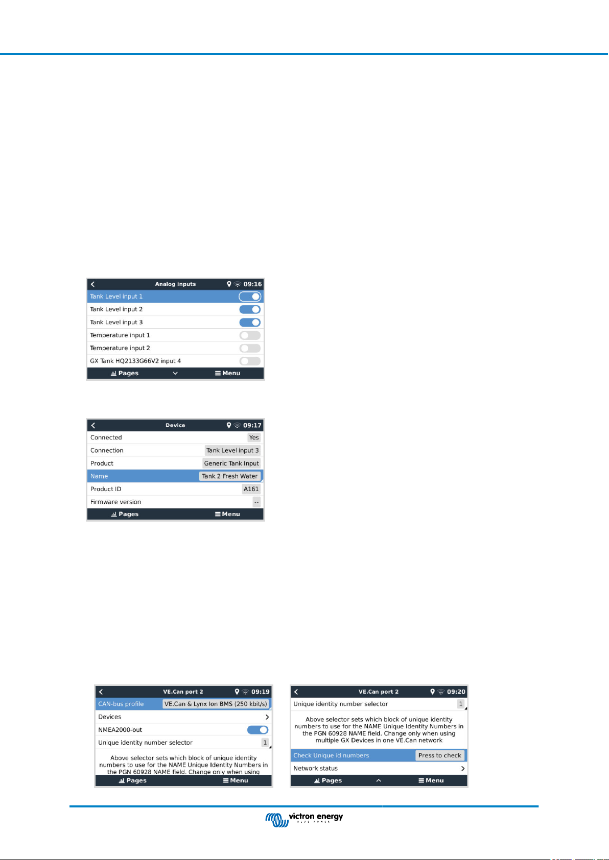
5.6. Increasing the number of tank inputs by using multiple GX devices
5.6.1. Introduction
The number of tank inputs on a GX device, such as the Cerbo GX and Venus GX, can be expanded by connecting multiple GX
devices together in a VE.Can network. To do this, one GX device must be designated to be the "main" and the others(s) to be the
"secondary" one(s). How this is done in practice is explained below.
There is no practical limit on how many GX devices can be used - except for the number of source addresses available in a
VE.Can network, which is 252 addresses. For example, a Cerbo GX with 4 tank inputs uses up to 5 addresses: one for itself and
one for each tank input.
Page 19
Connecting supported non-Victron
products
Page 26
Ekrano GX Manual
5.6.2. Requirements
1. Only enable the MQTT settings (part of MFD App integration [83]) on one of the GX devices, not multiple.
2. Only connect the main GX device to the Ethernet network - do not connect the others. The MFD App on Marine MFDs is not
designed to work with multiple GX devices on one Ethernet network.
3. In case you are using the ModbusTCP protocol: Enable ModbusTCP on only one of the GX devices.
4. Only connect the main GX device to VRM; it will also transmit tank levels received from the secondary units.
5. We recommend connecting all VE.Bus and VE.Direct products to the main GX device. Connecting through a secondary
device works, but has limitations. For example, remote configuration doesn't work, DVCC control will not work, and remote
firmware updates don't work either. Extending the VE.Direct ports via USB provides full functionality, which is therefore the
recommended method. You can find more information on this in chapter Powering the Ekrano GX [5].
5.6.3. Configuration step-by-step
1. First, on all GX devices, configure all tank inputs in Settings → I/O → Analog input, only enable the inputs in use, disable the
others.
2. In Device List → Tank input → Device → Name, give each tank input its own unique proper name, ie Fresh water 1, Gray
water SB, Diesel Port, and so forth.
This is the only way to make sure they are distinguishable once all connected together.
3. Connect each GX device together on its VE.Can port and make sure to terminate on both ends.
There is no need to power the VE.Can network externally: while the GX devices don't power the VE.Can network, they do
power their own internal CAN circuitry.
4. Now, on each GX device go to Settings → Services → VE.Can and there:
1. Verify that the chosen profile is VE.Can & Lynx Ion BMS (250 kbit/s) or VE.Can & CAN-bus BMS (250 kbit/s)
2. Enable the NMEA2000-out feature on all GX devices
3. Assign each GX device its own unique number
4. Use the Check Unique id numbers test feature when to make sure all went well
Page 20
Connecting supported non-Victron
products
Page 27

Ekrano GX Manual
5. Lastly, on the main GX device, check if all sensors show up in the Device List and work well.
5.7. Connecting third-party NMEA 2000 tank senders
A third-party NMEA 2000 tank sender must meet the following requirements to be visible on the GX device:
• Transmit the NMEA 2000 Fluid Level PGN, 127505
• The NMEA 2000 device class needs to either General (80) in combination with function code Transducer (190), or Sensor
(170). Or, the NMEA 2000 device class needs to be Sensors (75), in combination with function Fluid Level (150).
A single function reporting multiple Fluid Levels is currently not supported.
For some tank senders it is also possible to configure the capacity and the fluid type on the GX Device menus - for example the
Maretron TLA100. This facility may be available with other senders made by other manufacturers - it's well-worth trying.
Tested compatible NMEA 2000 tank senders:
• Maretron TLA100
• Maretron TLM100
• Navico Fluid Level Sensor Fuel-0 PK, partno. 000-11518-001. Note that you need a Navico display to configure the Capacity,
Fluid type, and other parameters of the sensor. See voltage warning below.
• Oceanic Systems (UK) Ltd (OSUKL) - 3271 Volumetric Tank Sender. In case it doesn’t work, it needs a firmware update.
Contact OSUKL for that. See voltage warning below.
• Oceanic Systems UK Ltd (OSUKL) - 3281 Water Level Sender. See voltage warning below
Most likely others work as well. If you know of one working well, get in touch with us on Community -> Modifications.
To connect an NMEA 2000 network to the VE.Can port on the GX device, which both have different type connectors, there are
two solutions:
1. The VE.Can to NMEA2000 cable. Which by either inserting or leaving out the fuse allows to either power the NMEA 2000
network with Victron equipment, or not. Take note of below warning.
2. The 3802 VE.Can Adapter by OSUKL. Its advantage is that it lends itself well to connecting a single NMEA 2000 device such
as a tank sender into a VE.Can network. It's also able to power a lower voltage NMEA 2000 network directly from a 48V
Victron system.
Warning and solution for 24V and 48V systems
Whilst all Victron components accept up to 70V input on their CAN-bus connections, some NMEA 2000 equipment does not. They
require a 12V powered NMEA 2000 connection, and sometimes work up to 30 or 36V. Make sure to check the datasheet of all
used NMEA 2000 equipment. In case the system contains NMEA 2000 that requires a network voltage below the battery voltage,
then either see above 3802 VE.Can Adapter by OSUKL. Or alternatively install the VE.Can to NMEA2000 cable without it’s fuse,
and provide suitable power to the NMEA 2000 network using for example a NMEA 2000 power adapter cable – which is not
supplied by Victron. The VE.Can port on the GX device does not need external power to operate.
Page 21
Connecting supported non-Victron
products
Page 28

Ekrano GX Manual
5.8. Mopeka Pro Check LPG and Water Bluetooth Sensors
Mopeka Pro Check-Water and Pro Check-Sensor LPG support has been added to VenusOS. These ultrasonic sensors use BLE
(Bluetooth Low Energy), a wireless technology that allows devices to be networked within a range of about 10 meters, while
consuming significantly less power compared to ordinary Bluetooth technology.
The Mopeka Pro sensors feature ultrasonic sensing for water and LPG tanks in horizontal or vertical cylinders and mount to the
bottom of those tanks by magnets. The liquid level, temperature and sensor battery voltage is streamed wirelessly to the GX
device.
To connect the Mopeka Pro sensors to the GX device via Bluetooth, the GX device needs Bluetooth functionality. Some GX
products already have built-in Bluetooth, all others can easily be retrofitted using a standard USB Bluetooth adapter (see the
Victron GX product range overview for GX products that have built-in Bluetooth).
However, an additional USB Bluetooth adapter, also for GX devices with built-in Bluetooth, allows for limited relocation of the
Bluetooth radio (via a USB cable extension) close to other supported Bluetooth devices that might not otherwise be reachable.
USB Bluetooth adapters that have been tested and known to work:
USB Bluetooth adapter
Insignia (NS-PCY5BMA2) Logilink BT0037 TP-Link UB400(UN) Kinivo BTD-400
Ewent EW1085R4 Laird BT820 Laird BT851 - -
A list of additional adapters that are also being tested, as well as adapters that have been tested and are known not to work, is
available here: Victron Community.
Ideapro USB bluetooth
adapter 4.0
5.8.1. Installation
The installation of the Mopeka Pro sensor is very simple. First, however, the sensor must be installed according to Mopeka's
installation instructions and configured via the Mopeka Tank app (available in Google Play and Apple App Store). Then the
installation and configuration is done in the GX device as described below.
1. Make sure Bluetooth is enabled in the Bluetooth sensors menu (enabled by default).
2. Go to Settings → I/O → Bluetooth sensors menu.
3. Move the Enable slider to the right to enable Bluetooth sensors.
4. To find your Mopeka Pro sensor, scroll down until you see them.
5. To activate the sensor, move the slider to the right. It should now appear on the Device List.
6. Repeat steps 1..5 for more than one sensor.
Page 22
Connecting supported non-Victron
products
Page 29

Ekrano GX Manual
5.8.2. Configuration
1. Go to the Device List menu.
2. Scroll up or down and select the appropriate sensor.
3. Press the right arrow key or space bar on that sensor to open up the sensor Setup menu.
4. Scroll down to Setup and right arrow key or space bar again to open up the sensors Setup menu.
5. In the Setup menu you can change the tank capacity, select the liquid type and volume unit, set up calibration values for
empty and full tank levels and read the actual sensor value.
6. After setup, go back to the Sensor overview menu.
7. Scroll down, select Device and press the right arrow key or space bar again to open up the device settings menu.
8. In the Device menu you can assign a custom name to the sensor and read out some additional device information.
9. Repeat steps 1..8 if you want to set up additional sensors.
Page 23
Connecting supported non-Victron
products
Page 30

Ekrano GX Manual
5.8.3. Tank level monitoring
Tank levels can be monitored at various locations within the GX environment:
• Device List of the GX device
• Sensor overview menu of the GX device
• Graphical overview of the GX device
• VRM Dashboard
• VRM advanced menu widgets
• VRM App widgets
Page 24
Connecting supported non-Victron
products
Page 31
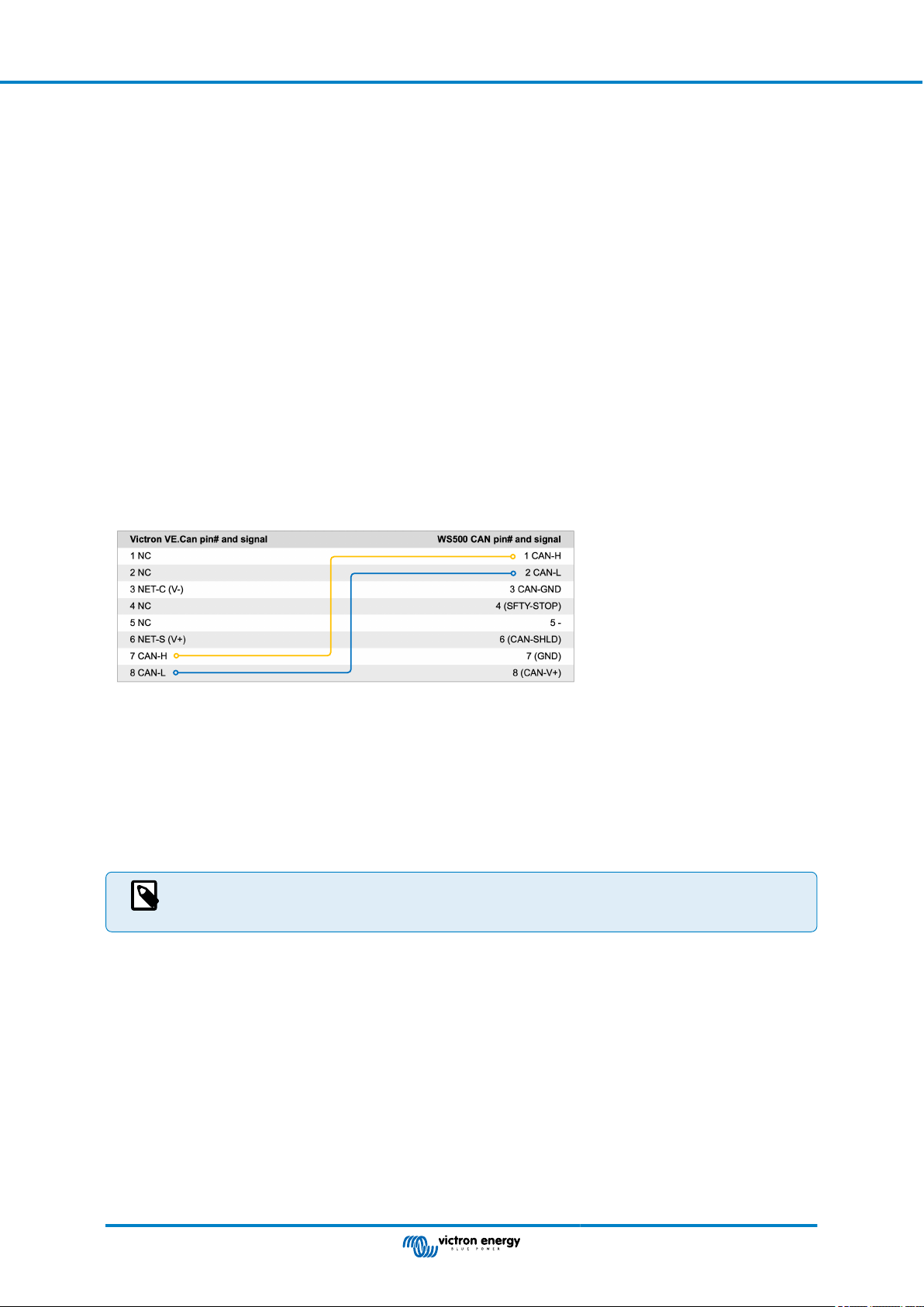
Ekrano GX Manual
5.9. Wakespeed WS500 alternator regulator support
5.9.1. Introduction
The WS500 is an external smart alternator regulator with CAN-bus and NMEA 2000 communication, which is especially
applicable in Marine and RV applications. The Wakespeed WS500 is supported by Venus OS and offers the possibility to monitor
the performance of your alternators via a GX device.
5.9.2. Requirements
Necessary requirements for the integration of the WS500 are:
1. VenusOS firmware v2.90 or higher installed on your GX device
2. Wakespeed WS500 firmware 2.5.0 or higher installed on the WS500 controller
3. The WS500 must connect to the VE.Can port of the GX device. It is not possible to monitor the WS500 when connected to
the BMS-Can port of a Cerbo GX.
5.9.3. Wiring the WS500 to VE.Can
Both, the WS500 and VE.Can, use RJ45 connectors for their CAN ports.
However, both have different pin outs. This means that a normal (straight UTP cable) network cable cannot be used. A crossover
cable is required. This crossover cable must be made by yourself. The following diagram reflect the pin out of the two devices.
The important pins to look at are pin 7 and pin 8 for CAN-H and CAN-L on the VE.Can side and pin 1 and 2 for Can-H and CAN-L
on the WS500 side.
Therefore a cable is needed where pin 1 and 2 on one side are connected to pin 7 and pin 8 on the other side. Pin 7 goes to pin 1
and pin 8 to pin 2.
The RJ45 connector with pin 7 and 8 on one end connects to the VE.Can port of the GX device. The other end of the cable with
pin 1 and 2 connects to the WS500 controller. Both sides must be terminated.
The cable colors do not matter for the do-it-yourself cable. Wakespeed also offers a ready-configured cable with a blue RJ45
connector on one end that must be connected to the VE.Can port.
Please note that the black terminators supplied by Wakespeed and the blue terminators supplied by Victron
are not interchangeable. Therefore: insert the Victron terminator on the Victron side of the network, and insert
the Wakespeed terminator into the Wakespeed.
Page 25
Connecting supported non-Victron
products
Page 32
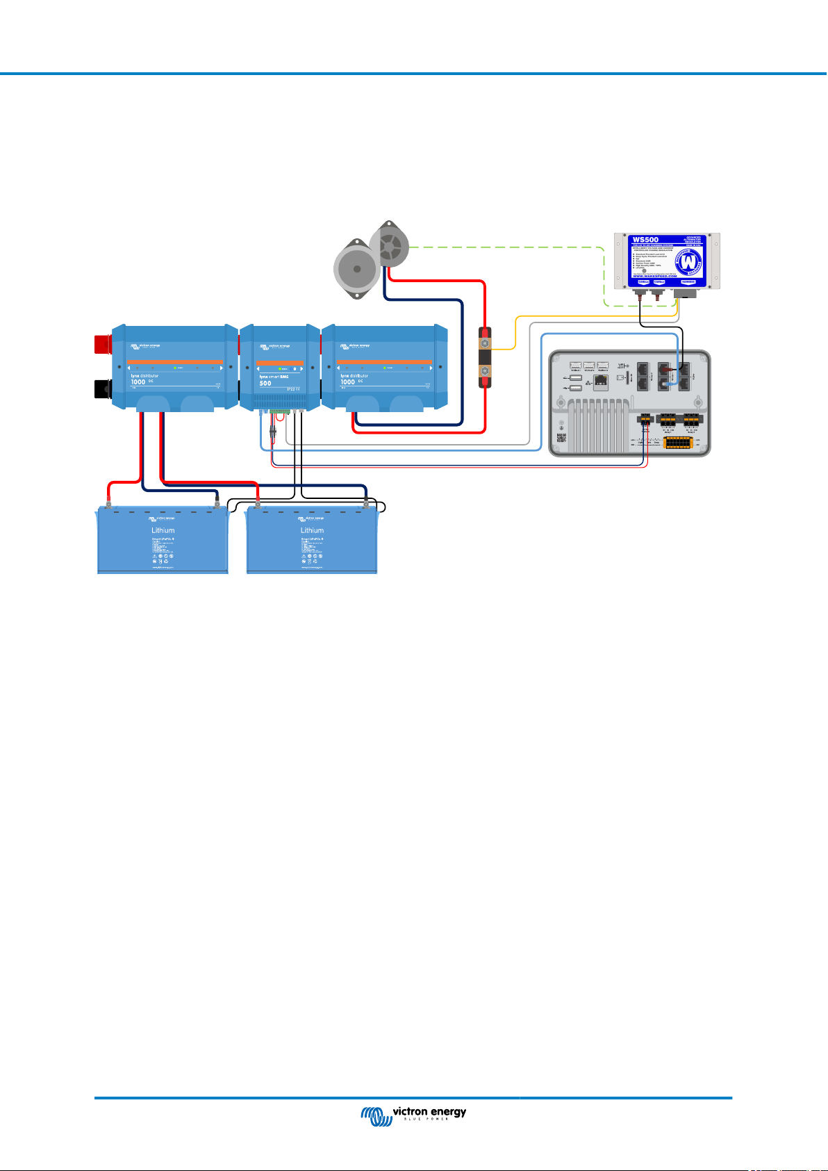
Ekrano GX Manual
5.9.4. Wiring Example
The example below shows an overview of the recommended wiring based on an installation with a Lynx Smart BMS, Lynx
Distributors and a Ekrano GX.
The correct placement of the alternator shunt (not to be confused with the shunt of the BMV or SmartShunt) is important here for
the correct connection of the current sense wire.
For complete wiring between the WS500 and alternator, see the WS500 and the alternator manual.
Alternator
Lynx Smart BMS and Lynx Distributors
Alternator ATC
Temperature sense
WS500
Current sense
Ekrano GX
Shunt
Page 26
Connecting supported non-Victron
products
Page 33

Ekrano GX Manual
5.9.5. GX device user interface for WS500
Once the WS500 is connected to the GX device, the Device list contains an entry for the regulator.
The WS500 menu then provides the following information and data:
• Output: voltage, current and power as reported from the alternator regulator
• Temperature: the alternator temperature as measured by the WS500 temperature sensor
• State: the charging state of the WS500
• Off when not charging
• Bulk, Absorption or Float when the WS500 is using its own charging algorithm
• External Control when controlled by a BMS such as Lynx Smart BMS
• Network Status:
• Standalone, if the regulator is working on its own
• Group Master, when it is supplying charging targets to another WS500 device
• Slave, when it is taking charging directions from another device such as a WS500 or a BMS
• Error: reflects any error state the WS500 might be in. The details of all error codes and messages can be found in the
Wakespeed Configuration and Communications guide. See also the appendix for error #91 and error #92
• Field Drive: report on the % of field drive being sent by the WS500 to the alternator on the field connection
• Speed: the speed in RPM at which the alternator is spinning. This is as reported by the stator feed and if this is wrong can be
adjusted by setting the Alt Poles option within the Wakespeed SCT configuration line
• Engine Speed: reported in RPM. This is reported by either
• calculation based on the alternator speed and the Eng/Alt drive ratio as set by the SCT configuration line
• NMEA 2000, if the WS500 is receiving engine RPM from PGN127488
• J1939, if the WS500 is receiving engine RPM from PGN61444
It is also possible to create a custom name for the WS500 in the Device menu. This triggers the WS500 to update the $SCN
configuration line of the regulator.
5.9.6. WS500 data on the VRM Portal
WS500 data that can be displayed on our VRM portal is current, voltage and temperature.
Currently 3 widgets are available on VRM
VRM custom widget showing WS500 voltage, current and temperature
Page 27
Connecting supported non-Victron
products
Page 34

Ekrano GX Manual
5.9.7. Troubleshooting & FAQ
For further assistance and troubleshooting please contact Wakespeed support directly.
Error code #91 and #92
Venus OS will report all errors that can be generated by the WS500 as defined within the Wakespeed Communications and
Configuration guide. In systems with integrated BMS, the following errors are critical as long as the events are active and require
special attention.
• #91: Lost connection with BMS
The WS500 has lost communication with the BMS and will drop into the configured get home mode. As soon as communication
is restored with the BMS, it will revert to following the charging goals as set by the BMS.
• #92: ATC disabled through feature IN
The BMS has signalled a charge disconnect event through the feature in wire and the WS500 has therefore reverted to an Off
status.
Current and power data are not displayed in the WS500 device menu
This does not constitute a problem and simply relates to how the system is installed and intended to be.
• No alternator shunt
• Alternator shunt installed but not properly configured. Check the ShuntAtBat setting and the Ignore Sensor setting using the
Wakespeed configuration tools.
[1]
The alternator shunt is a shunt that can be installed in series with the alternator to provide readout of alternator output current
and power. Its sense wiring connects directly to the WS500. This is an optional feature that is only for display purposes. If the
shunt is not installed, the GX device will show other alternator data, such as field % and output voltage etc., but not the alternator
output current and power.
[1]
installed
FAQ
Q1: Is the alternator output current (if actually measured) used for anything other than just display purposes?
A1: For the time being it's just for display purposes. Perhaps sometime in the future there will be DVCC integration, where the GX
device controls the amount of current you want the WS500 to generate, and then the GX device splits the desired charge current
between the WS500 and, for example, MPPTs.
Q2: What is the battery output current used for and can it be read over the canbus by a Lynx Smart BMS, other battery monitors
or even a GX device?
A2: Yes, the current can be read out via canbus and Lynx Smart BMS.
In this case the WS500 shunt can be configured for the alternator and thus report the amount of current the alternator is
producing. The Lynx Smart BMS current is used by the WS500 to ensure that no more than what the battery needs goes into the
battery. So if the battery calls for 100A and the WS500 reports 200A at the alternator, 100A will be used to support the loads. It
offers a greatly improved calculation for the DC load.
Q3: If the system includes a Lynx Smart BMS, are there any wiring recommendations?
A3: Yes. We have created extensive system examples that show the complete wiring and have been supplemented with
important additional information. For example a catamaran system with two WS500 or a system equipped with an additional
alternator controlled by one WS500. These examples can be used as a basis for your own system.
These system examples can be downloaded from the product page of the Lynx Smart BMS.
Q4: If the system does not include a Lynx Smart BMS, how do you recommend wiring?
A4: Wakespeed provides a quick start guide showing how to configure the regulator via DIP switches and an overview of all
wiring connections on the wiring harness that comes with the unit.
The WS500 product manual contains additional wiring diagrams that show in detail how the wiring harness is wired.
Note that the shunt should be connected to the battery and the WS500 configured with the shunt on the battery.
Page 28
Connecting supported non-Victron
products
Page 35

Ekrano GX Manual
5.10. Wireless Bluetooth Ruuvi temperature sensors
The Ruuvi sensor features temperature, humidity and atmospheric pressure streamed wirelessly to the GX device via Bluetooth.
To connect the Ruuvi sensors to the GX device via Bluetooth, the GX device needs Bluetooth functionality. Some GX products
already have built-in Bluetooth, all others can easily be retrofitted using a standard USB Bluetooth adapter (see the Victron GX
product range overview for GX products that have built-in Bluetooth).
However, an additional USB Bluetooth adapter, also for GX devices with built-in Bluetooth, allows for limited relocation of the
Bluetooth radio (via a USB cable extension) close to other supported Bluetooth devices that might not otherwise be reachable.
External USB Bluetooth adapters that have been tested and known to work:
USB Bluetooth adapter
Insignia (NS-PCY5BMA2) Logilink BT0037 TP-Link UB400(UN) Kinivo BTD-400
Ewent EW1085R4 Laird BT820 Laird BT851 - -
A list of additional adapters that are also being tested, as well as adapters that have been tested and are known not to work, is
available in this community thread.
Installation procedure
Make sure that Bluetooth is enabled in the Bluetooth menu (enabled by default).
Go to the Settings → I/O → Bluetooth sensors menu and then click Enable to enable Bluetooth temperature sensors.
The Ruuvi sensors come supplied with a removable plastic pull tab. This prevents it from discharging while on the shelf. Pull out
the plastic tab and the unit will start transmitting its temperature information.
Ideapro USB Bluetooth
adapter 4.0
The sensor should appear in the menu, "Ruuvi ####" - with a 4 hexidecimal device ID, enable the specific Ruuvi sensor.
The Bluetooth adapters submenu displays a list of available Bluetooth adapters. The menu option Continuous scanning
permanently scans for new Bluetooth sensors. Note that this option affects the WiFi performance of the GX device. Only enable
this option if you need to search for new Bluetooth sensors. Otherwise, leave this option disabled.
Page 29
Connecting supported non-Victron
products
Page 36

Ekrano GX Manual
If you have multiple sensors, you may wish to physically write this device ID on the sensor case itself to help keep track.
The sensor should now be visible in the main menu - by default it is labelled 'Generic temperature sensor (##)'
It is possible inside the temperature sensor menu to adjust the type, and also to set a custom name.
The Ruuvi sensors are estimated to last more than 12 months on a single replaceable CR2477 3V Li coin battery. Both the
internal battery voltage and the battery status are displayed in the menu of the respective sensor. Status 'Ok' = battery voltage
≤2.50V. Status 'Sensor battery low' = battery voltage ≥2.50V.
It is possible to update the firmware for the Ruuvi with Ruuvi's own separate phone app, though this is not necessary unless you
are experiencing issues.
Page 30
Connecting supported non-Victron
products
Page 37

Ekrano GX Manual
5.11. Connecting IMT Solar Irradiance, Temperature and Wind Speed Sensors
Ingenieurbüro Mencke & Tegtmeyer GmbH (IMT) offer a range of digital silicon irradiance sensor models within the Si-RS485
series that are all compatible with a Victron GX device.
Compatibility
The optional/additional external module temperature, ambient temperature and wind speed sensors are also supported.
Optional/additional external sensors are either connected to the solar irradiance sensor with pre-installed plugs or pre-wired
to the solar irradiance sensor (external module and ambient temperature only). When external sensors are connected via an
appropriate solar irradiance sensor, all measurement data is transmitted to the Victron GX device with the single interface cable.
Each model solar irradiance sensor within Si-RS485 series has a different capability with regards to external sensors (or comes
with an external sensor pre-wired), so carefully consider any future desires/requirements before initial purchase.
It is also possible to connect an independent IMT Tm-RS485-MB module temperature sensor (visible as ‘cell temperature’) or IMT
Ta-ext-RS485-MB ambient temperature sensor (visible as ‘external temperature’) directly to the Victron GX device, without a solar
irradiance sensor or in addition to one.
Operation
The IMT Si-RS485 series solar irradiance sensors operate using RS485 electrical interface and Modbus RTU communication
protocol.
The Victron GX device must be running version 2.40 or later.
The IMT sensor needs to be firmware version 1.52 minimum - for more information about this please contact IMT.
Physical connection to the Victron GX device is via USB port and requires a Victron RS485 to USB interface cable.
A suitable external DC power source (12 to 28 VDC) is also required - the sensor is NOT powered via USB.
Wiring Connections
The schematic in the installation guide below depicts the wiring configuration in a typical installation.
Wire connections
Si-Sensor Victron RS485 to USB interface Signal
Brown Orange RS485 Data A +
Orange Yellow RS485 Data B -
Red - Power Pos - 12 to 28VDC
Black Power Neg/Gnd - 0VDC
Black (thick) - Ground / Cable Shield / PE
- Red Power Pos - 5VDC (not used)
Page 31
Connecting supported non-Victron
products
Page 38

Ekrano GX Manual
Si-Sensor Victron RS485 to USB interface Signal
- Black Power Neg/Gnd - 0VDC (not used)
Brown Terminator 1 - 120R (not used)
Green Terminator 2 - 120R (not used)
Installation Notes
The maximum DC power supply voltage permitted for the IMT Si-RS485 series solar irradiance sensor range is 28.0VDC accordingly for 24V and 48V battery banks/systems an appropriate Victron DC-DC converter (24/12, 24/24, 48/12 or 48/24) or
AC-DC adaptor must be utilised in the installation.
For 12V battery banks/systems the IMT Si-RS485 series solar irradiance sensor range may be powered directly from the battery
bank and will continue to operate down to minimum voltage of 10.5V (as measured at the sensor, account for voltage drop in the
cable).
For detailed wiring/installation notes and specifications refer to the IMT Si-RS485 series solar irradiance sensor 'Quick Reference
Guide' and Victron RS485 to USB interface cable ‘Datasheet’.
To ensure signal integrity and robust operation, particularly ensure that;
• Extension cabling complies with the minimum cross-sectional area specifications in the related table - dependent on DC supply
voltage and cable length
• Extension cabling has appropriate shielding and twisted pair cores
• The original cable attached to the Victron RS485 to USB interface is reduced to a maximum length of 20cm in installations
where the total cable length is over 10m or there are installation/site specific interference issues – in this case appropriate/high
quality cabling should be used for the entire cable length, rather than only for the extension length
• Cabling is installed separated/away from the main DC or AC power cabling
• All wiring is properly terminated (including unused wires) and properly isolated from weather/water ingress
• The sensor housing is not opened or tampered with during installation - as sealing integrity will be compromised (and warranty
void)
The IMT Si-RS485TC series solar irradiance sensor includes internal Galvanic Isolation (up to 1000V) between power supply and
RS485 Modbus circuits, accordingly the non-isolated Victron RS485 to USB interface is suitable for most installations.
However, if an isolated RS485 to USB interface is preferred the only compatible device is Hjelmslund Electronics USB485-
STIXL (any others type will not be recognised by the GX device).
Multiple Sensors
It is possible to connect multiple IMT Si-RS485 series solar irradiance sensors to a common Victron GX device, however a
dedicated Victron RS485 to USB interface is required for each individual unit.
Multiple units cannot be combined on a single interface (as this is not supported by the related Venus OS software).
Configuration
There is normally no need for any special/additional configuration – the default ‘as shipped’ configuration is compatible for
communication with a Victron GX device.
However, in cases where the IMT Si-RS485 series solar irradiance sensor has been previously used in another system and/or the
settings changed for any reason, it is necessary to restore the default configuration before further use.
To revise the configuration, download the IMT 'Si-MODBUS-Configuration software tool'. Follow the instructions in the IMT ‘Si
Modbus Configurator Documentation’. and check/update the following settings:
• MODBUS Address: 1
• Baud Rate: 9600
• Data Format: 8N1 (10 Bit)
For further support related to configuration of the IMT Si-RS485 Series irradiance sensors please contact IMT Solar directly.
User Interface - GX device
Upon connection to the Victron GX device and power up the IMT Si-RS485 Series irradiance sensor will be automatically
detected within a few minutes and appear in the 'Device List' menu.
Page 32
Connecting supported non-Victron
products
Page 39

Ekrano GX Manual
Within the ‘IMT Si-RS485 Series Solar Irradiance Sensor’ menu all available parameters will be automatically displayed
(dependent on the sensors connected) and update in real time.
Within the ‘Settings’ sub-menu it is possible to manually enable and disable any optional/additional external sensors that are
connected to the IMT Si-RS485 Series irradiance sensor.
Page 33
Connecting supported non-Victron
products
Page 40

Ekrano GX Manual
5.11.1. Data Visualisation - VRM
To review logged historical data on the VRM portal, expand the ‘Meteorological Sensor’ widget list and select the ‘Meteorological
Sensor’ widget.
Data from all available sensor types will be automatically displayed in the graph. Individual sensors/parameters can also be
disabled/enabled by clicking on the sensor name/legend.
Page 34
Connecting supported non-Victron
products
Page 41

Ekrano GX Manual
6. Internet connectivity
Connect the Ekrano GX to the internet to get all the advantages of the VRM Portal. The EGX sends data from all connected
products to the VRM portal - from where you can monitor energy usage, view the current status of connected products,
configure email alarms and download data in CSV and Excel formats.
To monitor this data from your smartphone or tablet download the iOS or Android VRM App.
In addition to remote monitoring, an active internet connection allows the EGX to regularly check for a new firmware versions which (depending on the setting) will be automatically downloaded and installed.
There are several ways to connect a EGX to the internet:
• Run a network cable between a router and the EGX Ethernet LAN port
• Connect to the router wirelessly using WiFi
• Via a mobile (cellular) network, using the GX LTE 4G - a cellular USB modem or, with a 3G or 4G router
• USB Tethering via a mobile phone
This video explains how to connect LAN, WiFi and a GX GSM (also applies to GX LTE 4G):
6.1. Ethernet LAN port
When you connect an ethernet cable between a router and EGX, the Settings → Ethernet page of your EGX will confirm
connection.
Before connecting the ethernet cable, be very careful not to confuse the GX device Ethernet port with
the VE.Bus or VE.Can/BMS-Can ports!
Page 35 Internet connectivity
Page 42

Ekrano GX Manual
6.2. WiFi
The Ekrano GX includes built-in WiFi. Using WiFi it is possible to connect to WEP, WPA and WPA2 secured networks. It is also
possible to connect a supported external USB WiFi dongle (to increase wireless range outside of a cabinet for example).
There are several supported USB WiFi dongles. Two of them are also available from stock at Victron Energy:
• Partno. BPP900100200 - CCGX WiFi module simple (Nano USB), small, low cost.
• Partno. BPP900200300 - Asus USB-N14, slightly higher cost and also better reception than the Nano USB. Supported since
software version 2.23.
• Partno. BPP900200400 - WiFi module long range (Netgear AC1200) - higher cost and also better reception than the Nano
USB. Wireless AC, Wireless G and Wireless N; 2.4 Ghz and 5 Ghz.
WiFi modules that are no longer available but still supported are:
• Partno. BPP900200100 - Startech USB300WN2X2D
• Partno. BPP900100100 - Zyxel NWD2105
• Partno. BPP900200200 - Gembird WNP-UA-002, slightly higher cost and also better reception.
• Partno. BPP900200400 - Netgear A6210-100PES.
Although other WiFi dongles may work, they have not been tested and we do not offer support for other dongles.
The WiFi menu shows the available networks. When a network is selected, it is possible to fill in the password (if the password is
not already known) to connect to the network. Setting up via WPS (WiFi Protected Setup) is not supported.
When the EGX finds multiple WiFi networks of which the password is known, the strongest network is selected automatically.
When the signal of the connected network becomes too weak, it will automatically switch to a stronger network - if it knows the
password of that network.
WiFi is an inherently less reliable connection than a hardwired ethernet cable. It should always be a
preference to connect via ethernet when possible. Signal strength should always be at least 50%.
6.3. GX LTE 4G
Please see the GX LTE 4G Manual
6.4. Mobile (cellular) network using a 3G or 4G router
To connect the EGX to a mobile (cellular) network, such as a 3G or 4G network, use a cellular router. Connect the EGX to that
router with either a LAN cable or the router's WiFi network.
Make sure you use a router that is designed for unattended setups. Do not use low cost consumer-grade routers intended for
business or leisure travel. A more expensive professional router will quickly pay for itself, and you won't have wasted journeys
simply to perform a re-set. Examples of such professional routers are the H685 4G LTE from Proroute, as well as the Industrial
4G router range from Pepwave.
More information in this blogpost.
Note that the EGX does not support USB 3G/4G dongles, other than the GX GSM and GX LTE 4G accessories available from
Victron.
Page 36 Internet connectivity
Page 43

Ekrano GX Manual
6.5. USB tethering using a mobile phone
This is a useful facility when it works - but don't rely on it because it has not proved very dependable. Consult the internet for
instructions about tethering for your phone and its particular operating system. We have heard of it working on:
• Samsung Galaxy S4
…but not on:
• iPhone 5s with iOS 8.1.1
6.6. Manual IP configuration
Almost no installations will need the IP address configuration to be inserted manually as most systems support automatic IP
configuration (DHCP) - and that is also the EGX default setting. If you do need to configure the address manually, select the
following template:
Complete details of IP requirements, as well as used port numbers will be found in the VRM FAQ - ports and connections used by
the [125] EGX.
6.7. Connecting both Ethernet and WiFi (failover)
It is possible to connect the EGX to both Ethernet and WiFi. In this case, the EGX will try to determine which interface provides an
active internet connection and then use that interface. When both have an active internet connection, the Ethernet connection is
used. The EGX will automatically check again for active internet connections when something changes on the interfaces.
6.8. Minimise internet traffic
In situations where internet traffic is expensive, for example a satellite uplink or with roaming GSM/cellular charges, you may want
to minimise the internet traffic. The steps to take are:
• Disable auto firmware updates [58]
• Do not enable remote support [126]
• Reduce the Log interval (Settings → VRM online portal → Log interval) to a very low frequency. Note that state changes
(charging → inverting, or bulk → float) and also alarms will cause extra messages to be sent
To find out how much data allowance you need to buy the best way is to let the system run for a couple of days and monitor
the internet RX and TX counters in your 3G or 4G router. Or even better, some mobile companies will report the data used via a
website.
The amount of data used is also very dependent on the system:
More products connected to the EGX will generate more data.
• A state change (from inverter to charger for example) will trigger a data transmission, so a system with very frequent state
changes will also tend to generate more data. This is especially true in certain Hub-1 and Hub-2 systems.
We recommend setting-up your data plan in such a way as to avoid costly 'excess' charges. Make sure you put a cap on your
data usage; or use a pre-paid plan.
One customer - burdened with global costs of between twenty cents and several euros per mb of data - invented a clever
solution: Using a VPN he modified the IP to route ALL traffic to and from the GX device via his VPN. Using a firewall at the VPN
server allows him to control traffic according to time, connection type, place and destinations. Although this is beyond the scope of
this manual, it works, and - with the help of a Linux and networking expert - it can work for you.
Page 37 Internet connectivity
Page 44

Ekrano GX Manual
6.9. More information about setting up an internet connection and VRM
• Setting up a VRM account
• VRM Portal alarms and monitoring
• VRM Portal - Frequently asked questions
Page 38 Internet connectivity
Page 45

Ekrano GX Manual
7. Accessing the GX device
It is possible to access the GX device via a smartphone, tablet or computer. This access is called Remote Console. The Remote
Console is the central element for making or changing settings on the GX device.
In GX devices with a display this Remote Console feature may be disabled by default and need to be enabled. GX devices
without a display have Remote Console enabled by default.
There are several ways to get access:
Access type Color Control GX Venus GX Cerbo GX /
Ekrano GX
Cerbo-S GX
VictronConnect via
Bluetooth
[4]
Built-in WiFi Access
[1]
-
[2]
-
[1]
-
Yes Yes
Yes Yes Yes
Point [41]
Local LAN/WiFi
Yes Yes Yes Yes
network [42]
VRM Portal
[1]
Both CCGX and VGX do not have built-in Bluetooth. This feature can be easily added by connecting a USB Bluetooth
[3]
Yes Yes Yes Yes
dongle.
[2]
The CCGX does not have built-in WiFi. This feature can be easily added by attaching a USB WiFi dongle.
[3]
Requires the GX device connected to the internet.
[4]
GX device Bluetooth functionality is limited to assist with initial connection and networking configuration. You cannot
use Bluetooth to connect to the Remote Console or other Victron products (e.g. SmartSolar charge controllers). For more
information about how to connect other Victron products, please see Connecting Victron products [9].
Page 39 Accessing the GX device
Page 46
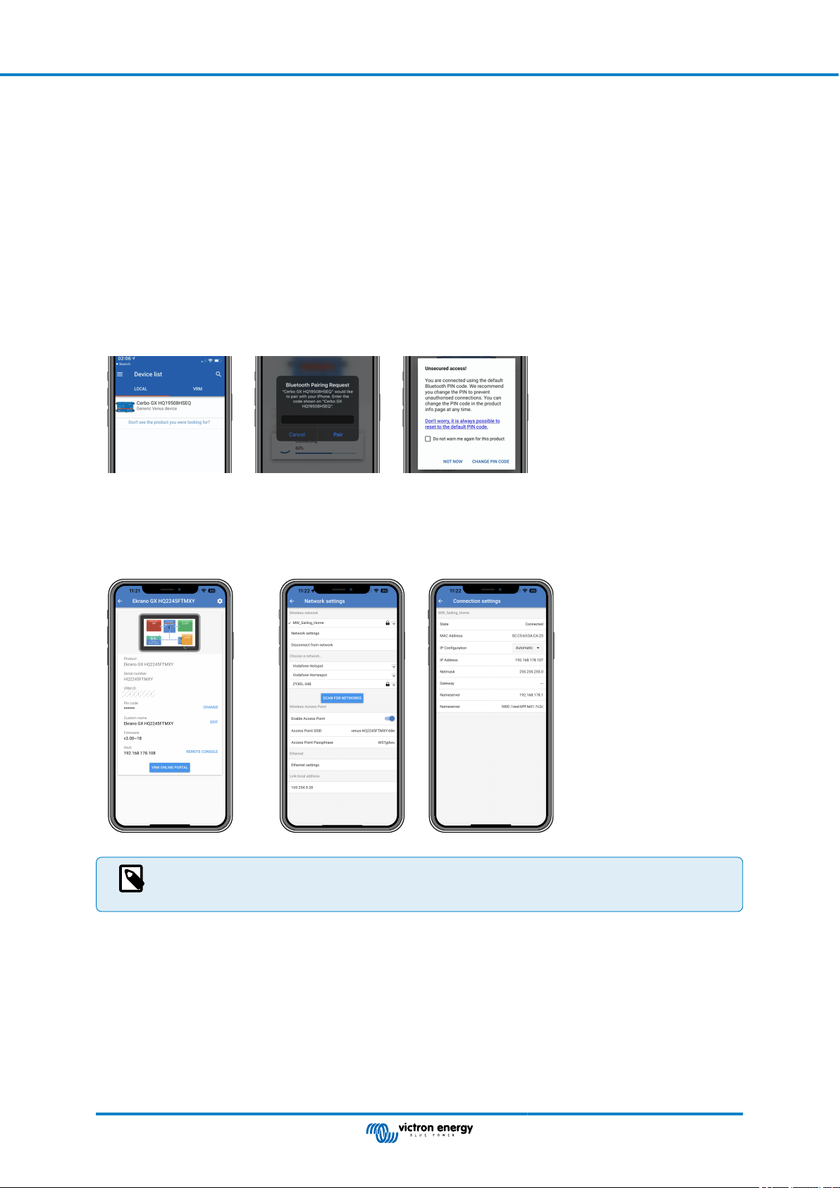
Ekrano GX Manual
7.1. Using VictronConnect via Bluetooth
If you are just getting started for the first time with VictronConnect, you may wish to begin with the VictronConnect manual.
1. Download the latest version of the VictronConnect app onto your Bluetooth compatible device (phone or laptop), and make
sure that Bluetooth is enabled.
2. Make sure the Ekrano GX is powered on.
3. Open the VictronConnect app within 10 meters of the Ekrano GX and wait for nearby devices to be discovered.
4. Once discovered, click or tap on the Ekrano GX.
5. On first connection you will be asked to enter a Bluetooth PIN code.
The unique PIN code is printed on a sticker on the topside of the Ekrano GX.
6. For GX devices that use the default PIN code, you will then be asked to change this insecure default PIN code to a more
secure unique code. Please set your unique code, and then put it in a safe place for passwords in case you forget.
From the main device screen it is possible to change the network and ethernet settings, enable or disable the built-in WiFi Access
Point, view the system on VRM, or open the Remote Console (requires a WiFi connection to a local network or the access point
of your GX device).
For the network settings, tap or click the cog wheel icon.
Bluetooth can only be used for initial connection and networking configuration, and cannot connect to other
Victron products such as SmartSolar charge controllers. If you need to connect other Victron products, please
refer to the Connecting Victron products [9] chapter.
Page 40 Accessing the GX device
Page 47

Ekrano GX Manual
7.2. Accessing via built-in WiFi Access Point
This method requires the VictronConnect app to be installed on your smartphone, tablet or laptop.
Steps to connect automatically via the QR Code:
1. Locate the QR code sticker on the side of the EGX
2. Scan the QR code using your phone's camera function, or a QR code scanning app
3. If supported by your phone, this will prompt you to connect you to the WiFi Access point
4. Once connected, open VictronConnect
5. Select the GX device from the list
6. Open the Remote Console
Steps to manually connect:
1. Stand as close as possible from the Ekrano GX, and no further than a few meters away.
2. Go to the WiFi settings on your phone, tablet or laptop.
3. After searching, the Ekrano GX will show up in the list, as Venus-HQ1940DEFR4-3b6. Where HQ… is the serial number as
printed on the side of the box.
4. Connect to WiFi using the 'WiFi key' which you will find printed on the side of the box …and also on a card in the plastic bag.
Keep that in a safe place.
5. Open VictronConnect, it will start scanning the WiFi network automatically.
6. Once found, select the GX device from the list.
7. Open the Remote Console
Notes:
• If you cannot use VictronConnect, you can use a web browser and navigate to the IP address http://172.24.24.1 or http://
venus.local
• For added security it is possible to disable the WiFi Access Point. See Settings → Wi-Fi → Create access point in the Remote
Console.
Instruction video
Watch the step-by-step instruction video on how to connect to a GX device using the VictronConnect app:
Page 41 Accessing the GX device
Page 48

Ekrano GX Manual
7.3. Accessing the Remote Console via local LAN/WiFi Network
This section explains how to connect to Remote Console when the Ekrano GX is connected to the local computer network with
either an Ethernet cable, or having it configured to connect to a local WiFi network.
This method does not require an internet connection. Just a local computer network is sufficient.
Once connected, connect to the GX device by running the VictronConnect app on a phone, tablet or laptop.
to be connected to the same computer network as the Ekrano GX.
This video shows how it is done.
7.3.1. Alternative methods to find the IP address for Remote Console
In case VictronConnect can't be used, here are a few other methods to find the Ekrano GX, ie. its IP address.
Note that it will need
Link Local Address - Venus.local
When the Remote Console on LAN setting is enabled, a direct connection (via network cable without a router or DHCP server)
is possible. You can access the GX device by typing venus.local or http://venus.local into a web browser, or in VictronConnect
when connected to the same network. Only enable this function on trusted networks or direct connections. Make sure you have
disabled the password check, or set a password first.
IP Address on VRM
On the VRM Portal, you'll find the IP address on the Device list page of the installation. Note that this does require the Ekrano GX
to be connected to the internet.
Network (on Microsoft Windows)
Page 42 Accessing the GX device
Page 49

Ekrano GX Manual
In a local network, for example at home, you can also find the Ekrano GX in the Windows 'Network' overview (this uses Universal
Plug-and-Play (UPnP) broadcast technology):
Double-clicking the icon will open up Remote Console on LAN.
Open the 'Properties' window by right-clicking the icon to see the IP address.
7.4. Accessing via VRM
This method requires a working internet connection, both on your phone, tablet or laptop as well as for the Ekrano GX. For a new
install, this means that it needs to be connected by Ethernet cable.
Step-by-step instructions:
1. First, connect the Ekrano GX to the internet by plugging it into a working Ethernet network which has a DHCP server, as
most networks do, and which is connected to the internet.
The Ekrano GX will immediately connect to VRM.
2. Now go to the VRM Portal, https://vrm.victronenergy.com/, and follow the instructions to add the device.
3. Then, once visible on VRM, click on the Remote Console link in the left-hand menu.
The result looks similar to the image above.
Page 43 Accessing the GX device
Page 50

Ekrano GX Manual
More technical information in the related troubleshooting chapter: Remote Console on VRM - Troubleshooting [81].
7.5. The Remote Console menu
The Remote Console menu (Settings → Remote Console) contains options for controlling access to the Remote Console via
LAN/WiFi and VRM and shows the online status of the Remote Console on VRM.
The options in detail:
1. Disable password check:
If this option is disabled, there is no password check when accessing the Remote Console.
2. Enable password check:
To enable password check, a password must first be assigned. Use this password when accessing the Remote Console.
Keep it in a safe place.
3. Enable on VRM:
If enabled, the Remote Console can be used via the VRM portal from anywhere in the world. The password check
(recommended) also applies if it is activated.
4. Remote Console on VRM - status:
Displays the online status of the Remote Console on VRM.
5. Enable on LAN:
If enabled, the Remote Console can be used via local LAN/WiFi. Mind the security warning.
Note that you need to manually reboot (Settings → General → Reboot) the GX device after changing any of these settings.
Page 44 Accessing the GX device
Page 51

Ekrano GX Manual
8. Configuration
8.1. Menu structure and configurable parameters
After completing the installation and setting up the internet connection (if required), go through the menu from top to bottom to
configure the EGX:
Item Default Description
General
Access level User and installer Set this to 'User' to prevent accidental and unwanted changes
to the configuration. Installer has additional privileges and once
changed from default requires a password. Password is available
from your dealer.
Remote support No No / Yes - Enable this to allow Victron engineers to access your
system in case there is a problem.
Reboot? Reboots the GX device
Audible alarm Yes When there is an alarm on the EGX or a connected product, the
EGX will beep - unless this setting is set to 'Off'.
Demo mode Disabled Demonstrates product and installation features to a client or at an
exhibition. This simulation mode will allow better understanding
without (yet) changing any settings. Note that this will add
simulated devices to a VRM installation. Demos for ESS, Boat
and Motorhome are available.
Firmware - Read full feature description [58]
Firmware Version x.xx Displays the currently installed firmware version.
Build date/time xxx Displays the build number.
Note that for most system applications our advise is to keep automatic updates disabled; as is also the
default factory setting.
Instead, update the system at a convenient moment; when people are on location and ready to revert to a
previous system and/or troubleshoot in case of issues.
Online updates: Auto
update
Online updates: Update
feed
Online updates: Image
type
Online updates: Check for
updates
Install firmware from SD/USB Use this menu to install a new version from a microSD card
Stored backup firmware With this feature you can go back to the previously installed
Date & Time
Date/Time UTC Automatic from
Date/Time local Automatic from
Time zone Select the correct local time zone.
Remote Console - Read full feature description [39]
Disable password check Password authentication not required for Remote Console access.
Check only If this is Enabled, the GX device will check with the server to see
if there is a new version available. It is possible to set to disable,
or update automatically
Latest release Use the default setting unless you want to participate in test
versions. End-user systems should certainly be set to 'Latest
release'.
Normal Choice between Normal and Large image. The large image adds
Node-RED and the Signal K-Server functionality to the image.
Press to check Click or press the spacebar to check if a new firmware update is
available.
or USB stick. Insert the card or stick that holds the new
firmware .swu file.
firmware version.
-
internet
When connected to the internet, time will be automatically
internet
synchronised regardless of this setting. Toggle this setting to
manually input the time where no internet connection is present.
Page 45 Configuration
Page 52

Ekrano GX Manual
Item Default Description
Enable password check Choose password to allow Remote Console access.
Enable on VRM No No / Yes - Enabling on VRM will allow connection to the EGX from
anywhere via the VRM portal. See also Troubleshooting Remote
Console on VRM [81]
Remote Console on VRM status
Enable on LAN No No / Yes - Enabling will allow direct connection to the EGX
System setup
System name Automatic Select the system name - presets or user defined
AC input 1 Generator Select Not available, Generator, Grid or Shore power. Note:
AC input 2 Grid Same choices as above.
Monitor for grid failure Disabled Monitors for loss of AC-input and triggers an alarm if detected.
Battery monitor Automatic Select the SoC source. This function is useful where there is
Has DC system Disabled Enable this for boats, vehicles and installations with DC loads and
Battery Measurements Not set Use this menu to define which battery measurement to see on the
System status On/Off The following parameters are diagnostic flags only. See The
DVCC - Read full feature description [67]
DVCC Disabled Enabling DVCC changes a GX device from a passive monitor into
Limit charge current Disabled User-configurable system wide maximum charge current setting
Limit managed battery
charge voltage
SVS - Shared voltage
sense
- Displays the connection state of the VRM Remote Console
Feature: Online, Offline, Disabled.
by typing its IP address or Venus.local into a web browser,
or in VictronConnect when connected to the same network.
Only enable this function on trusted networks. Disable password
check, or set password first.
additional configuration is required for complete setup of these
options.
Alarm is cleared when the AC-input is reconnected.
more than one BMV. Options: Automatic, No battery monitor and
available battery monitor sources. For more details see Battery
state of charge (SoC) [52].
chargers - in addition to Multi and MPPT chargers. This won't
be applicable to most off-grid installations; and any discrepancy
between the DC current measured by the Multi, and by the BMV,
will be attributed to a 'DC system'. This may be power-in from an
alternator, or power-out from a pump, for example.
A positive value indicates consumption. A negative value
indicates charging, for example by an alternator.
Note that the value shown will always be an approximation, and is
affected by the variation in sample rate between elements of the
system.
VRM portal and the MFD HTML5 app.
System Status Menu [54] chapter for details
Synchronise VE.Bus SoC with battery
Use solar charger current to improve VE.Bus SoC
Solar charger voltage control
Solar charger current control
BMS control
an active controller. Default setting is No, unless a compatible
BMS-Can managed battery is connected, then setting is set and
locked to manufacturers specification.
in Amps.
Disabled Only use this option for 15s Pylontech batteries on initial
balancing. Using it for other purposes may have undesirable side
effects.
Disabled The GX device automatically selects the best available voltage
measurement and shares it with other connected devices.
Page 46 Configuration
Page 53

Ekrano GX Manual
Item Default Description
STS - Shared temperature
sense
Temperature sensor Automatic Select the temperature sensor to use for shared temperature
SCS - Shared current
sense
Controlling BMS Automatic Select the BMS that controls the battery.
SCS status - Describes if SCS is enabled, or why it is disabled
Display & language
Display off time - Set time-to-off between 10s / 30s - 1m / 10m /30m - or never
Show boat & motorhome
overview
Language English Choose between English, Dutch, Chinese, German, Spanish,
Units °C The available options are Celsius and Fahrenheit. Please note
VRM online portal - Read full feature description [75]
Logging enabled Enabled Enable or disable logging
VRM Portal ID - Use this value when registering the GX device onto the VRM
Log interval 15 minutes Set to anything between 1 minute and 1 day. Choose longer times
Use secure connection
(HTTPS)
Last contact - Time since the VRM server was last contacted
Connection error No error Displayed if there is an error in VRM communications. See here
VRM two-way
communication
Reboot device when no
contact
No contact reset delay
(hh:mm)
Storage location Internal storage Displays if an external storage device (eg USB drive or microSD
Free disk space - Amount of bytes available on the storage device
microSD/USB - Select to safely eject an external microSD or USB storage (if one
Stored records - How many records are stored locally when no internet connection
Oldest record age - If internet/VRM is not available, then this will display the oldest
ESS - An Energy Storage System (ESS) is a specific type of power system that integrates a power grid connection with a
Victron Inverter/Charger, GX device and battery system. Read full feature description.
Disabled The GX device will send the measured battery temperature to the
inverter/charger system as well as all connected solar chargers.
sense measurement.
No Forwards the battery current, as measured by a battery monitor
connected to the GX device, to all connected solar chargers.
Disabled Enable this to show the mobile overview page which is designed
for Marine and Remote Vehicle applications. This overview gives
direct access to the AC Current limit as well as the On/Off/
Charger-only settings and pump control. Also shows up to four
tank levels.
French, Italian, Swedish, Turkish, Czech, Dansk, Polish, Russin
and Arabic.
that this setting does not affect the temperature unit in the VRM
portal.
Portal
on systems with an unreliable connection. Note that this setting
does not affect reporting problems and state changes (bulk →
absorption) to the VRM Portal. These events initiate an immediate
transmission of all parameters.
Yes This encrypts the communication between the GX device and the
VRM server
for more details on troubleshooting VRM errors. [77]
Disabled Enable for VRM: Remote VEConfigure and VRM: Remote
firmware update
Disabled The GX device will reset itself to attempt to correct a potential
networking issue if the internet connection is lost for the set delay
period
01:00 How long the unit must be offline before restarting itself
card) is mounted, or the internal storage is in use
is connected) before physically removing it. Failure to do so can
cause data loss.
is available. The GX device will store as many records as it can
locally, then upload them when internet is available again.
record stored on the GX device.
Page 47 Configuration
Page 54

Ekrano GX Manual
Item Default Description
Mode Optimized (with
BatteryLife)
Grid metering - Leave at default when there is no external Victron grid meter
Inverter AC output in use Enabled Setting this to 'No' hides the AC-out graphic in the overview pane.
Multiphase regulation - Use the Phase compensation setting in systems with a three-
Minimum SOC (unless grid
fails)
Active SOC limit 10% Use this setting to see the current BatteryLife SoC level.
BatteryLife state Self-Consumption Self-consumption, Discharge disabled, Slow charge, Sustain,
Limit charge power Disabled This setting limits the flow of power from AC to DC for battery
Limit inverter power Disabled Limit the power drawn by the Multi: ie. limit the power being
Grid setpoint 50W This sets the point at which power is taken from the grid when the
Grid feed-in - Set and limit grid feed-in: AC-coupled PV feed in excess, DC-
Scheduled charge levels Inactive Allows you to set up to five scheduled periods, during which the
Energy meters - Read full feature description
Role Grid meter Grid meter, PV inverter, Generator, AC meter
Phase type Single phase Either multi- or single-phase
PV inverters - Read full feature description
Inverters: - Shows connected AC PV inverters
Inv: Position AC Input 1 AC input 1, AC input 2, AC Output
Inv: Phase L1
Inv: Show Yes
Find PV inverters - Scan for available PV inverters
Detected IP addresses - Shows the IP address of PV inverters that have been discovered
Add IP address manually - If an inverter has a manually assigned IP address, you can add it
Automatic scanning Enabled This setting will continue to look for PV inverters, this can be
Wireless AC sensors
Select the position for each AC sensor (PV Inverter on AC-input 1, 2 or on AC-output). More information about the Wireless
AC sensors.
Modbus TCP devices
Automatic scanning Enabled Scans automatically for Modbus TCP devices
Scan for devices - Manually trigger a scan for Modbus TCP devices
Devices - Displays a list of found Modbus TCP devices and their IP address
Ethernet - read full feature description [35]
State Unplugged The state is either unplugged, connecting or connected
MAC address -
IP configuration Automatic Options: Automatic (DHCP) and manual IP address allocation
IP address -
Netmask -
10% Configurable minimum SoC limit. ESS will supply loads from the
Optimized (with BatteryLife) and Optimized (without BatteryLife),
Keep batteries charged, External control
installed.
phase connection to the utility grid.
grid once the SoC has fallen to the configured setting - except
when the utility grid has failed and the system is in Inverter mode.
Recharge
charging from AC-in.
inverted from DC to AC.
installation is in self-consumption mode.
coupled PV feed in excess, Limit system feed-in
system will take power from the grid to charge the battery.
directly here.
useful if using a DHCP assigned IP address that might change.
Page 48 Configuration
Page 55

Ekrano GX Manual
Item Default Description
Gateway -
DNS server -
Link-local IP address -
WiFi - Read full feature description [36]
Create access point Enabled Disables the internal WiFi access point
Wi-Fi networks - Displays a list of available WiFi networks and/or the network to
which the GX device is connected
Name - SSID of the Wifi network
State Connected
Forget network - Press to “forget” the network if you want to connect to a different
network or troubleshoot
Signal strength %
MAC address -
IP configuration Automatic Options: Automatic (DHCP) and manual IP address allocation
IP address -
Netmask -
Gateway -
DNS server -
GSM modem - Read full feature description
GPS - Read full feature description [16]
GPS information - Status, Latitude, Longitude, Speed, Course, Altitude, Number of
satellites
Device - Displays device related information for diagnostic
Format DDD.DDDDD° Choose between decimal degrees, degrees and decimal minutes
or degrees, minutes and seconds display
Speed unit km/h Choose between km/h, meters per second, miles per hour, or
knots.
Generator start/stop - Read full feature description [114]
State Stopped Displays if the generator is running or not
Error No error Displays if there is an error (e.g. generator is supposed to be
running but no AC input is detected)
Total run time hh:mm Total time the generator has been running since reset.
Time to next test run hh:mm If a periodic run is programmed, this counter will display in days,
and hours how long before that will occur.
Auto start functionality Disabled Enable or disable the Autostart functions, this can be further
configured in the Generator → Settings → Conditions menu
Manual start - Start generator, Run for hh:mm
Daily run time - Submenu shows the history of time the generator has been
running (minutes) each day for the previous 30 days.
Generator start/stop → Settings
Generator start/stop → Settings → Conditions
On loss of communication Stop generator Stop, Start, Keep generator running
Do not run generator when
AC1 is in use
No This option is ideal for back-up systems where a Quattro has
mains/grid electricity connected to its AC-in 1 terminal, and
a Genset connected to its AC-in 2 terminal. With this option
enabled, the Genset will only start after a mains failure.
Page 49 Configuration
Page 56

Ekrano GX Manual
Item Default Description
Battery SOC No Use Battery SOC value to start/stop - No / Yes
Start when SOC is lower than - %
Start value during quiet hours - % (to override programmed quiet
hours when absolutely necessary)
Stop when Battery SOC is higher than - %
Stop value during quiet hours - % (allows for less runtime during
quiet hours, once system is recovered)
Battery current
Battery voltage
AC output
Inverter high temperature
Inverter overload
Generator start/stop → Settings → Conditions → Periodic run
Periodic run No Enable - No / Yes
Generator start/stop → Settings
Minimum run time 0 The minimum number of minutes the generator will run for any
Detect generator at AC
input
Quiet hours 0 Quiet hours will prevent normal generator run conditions from
Reset daily run time
counters
Generator total run time
(hours)
Tank pump - Configure automatic starting and stopping of pump based on tank level(sender) information. Pump auto start/
stop with Color Control GX
Pump state - Displays if the pump is running or not
Mode Auto Options are Auto, On and Off. This is the manual override to the
Tank Sensor Automatic Select the tank sensor that is used for the tank pump trigger. 'No
No Use value to start/stop - No / Yess
Start when value is higher than - Amps / Voltage / Watts
Start value during quiet hours - Amps / Voltage / Watts (to
override programmed quiet hours when absolutely necessary)
Start after condition is reached for - seconds (to allow for
momentary spikes to pass without triggering start)
Stop when value is lower than - Amps / Voltage / Watts
Stop value during quiet hours - Amps / Voltage / Watts (allows for
less runtime during quiet hours, once system is recovered)
Stop after the condition is reached for - seconds (to allow for
momentary dips without stopping the running generator)
No Start on value warning - No / Yes
Start when warning is active for - seconds (to allow for
momentary spikes to pass without triggering start)
When warning is cleared stop after - seconds (to allow for
momentary dips without stopping the running generator)
Run interval
Skip run if has been running for
Run interval start date
Start time
Run duration (hh:mm)
Run until battery is fully charged
time that it is started, even after stop conditions.
No No / Yes - An alarm will be triggered when no power from the
generator is detected at the inverter AC input. Make sure that the
correct AC input is set to generator on the system setup page.
starting the generator. It is possible for some settings to specify
override values to the quiet hours ( an extremely low battery
voltage trigger to prevent a system shutdown for example)
An option to reset generator run time counters, for example if
these are used for service, or if the generator is replaced or
majorly repaired.
The total time the generator has been running since the counter
was reset.
start and stop level triggers when a tank sensor is connected.
tank sensor' will be displayed if no tank sensor is connected or
detected,
Page 50 Configuration
Page 57

Ekrano GX Manual
Item Default Description
Start level 50% The trigger point of the tank level to start the tank pump (close the
relay).
Stop level 80% The trigger point of the tank level to stop the tank pump (open the
relay).
Relay
Function Alarm relay Select the relay function. Possible functions are 'Alarm relay',
'Generator start/stop', 'Tank pump', 'Temperature', and 'Manual'.
Polarity Normally open Select the polarity of the relay on the back of the EGX. 'Normally
open' or 'Normally closed'. Note that setting it to Normally closed
increases the EGX power draw. This option is only available when
configured as an alarm relay.
Services
ModbusTCP Off This setting enables the ModbusTCP service. More information
about ModbusTCP in this document and in the communications
white paper https://www.victronenergy.com/upload/
documents/Whitepaper-Data-communication-with-Victron-Energyproducts_EN.pdf
MQTT on LAN (SSL) On Enables MQTT on LAN - More information on MQTT is available
on Victron Community.
MQTT on LAN (Plaintext) Off This setting is required to be enabled when connecting a Marine
MFD
VE.Can port VE.Can CAN-bus profile (Disabled, VE.Can & Lynx Ion BMS 250 kbit/s,
VE.Can & Can-bus BMS 250 kbit/s, CAN-bus BMS 500 kbit/s,
Oceanvolt 250 kbit/s, RV-C 250 kbit/s). Additional options:
Devices, NMEA2000-out, Unique identity number selector, Check
unique ID numbers, Network status
CAN-bus CAN-bus profile, Send data to VE.Can, Unique device number for
VE.Can, Check unique numbers
I/O
Page 51 Configuration
Page 58
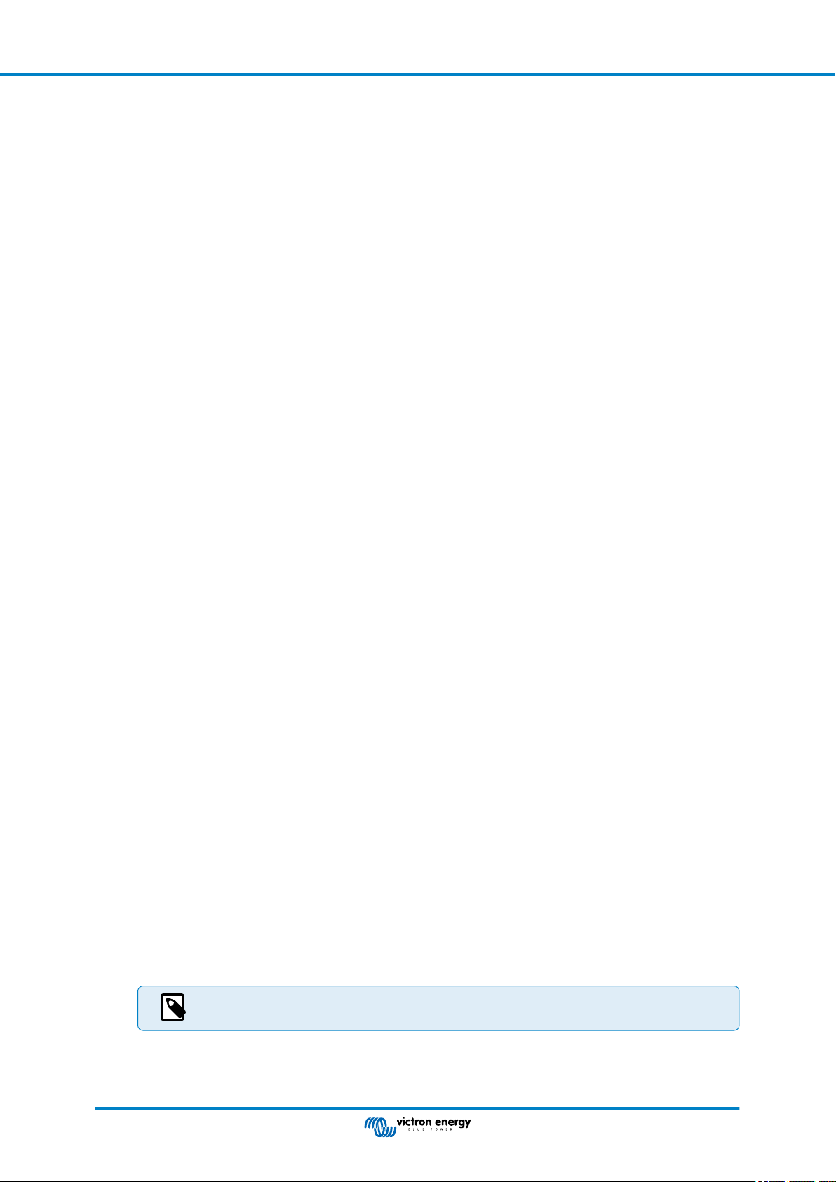
Ekrano GX Manual
8.2. Battery state of charge (SoC)
8.2.1. Which device should I use for SoC calculation?
There are three products types that calculate state of charge (SoC). The EGX itself does not calculate SoC, it only retrieves it
from the connected devices. The three products that calculate SoC are:
1. Battery Monitors, such as the BMVs, SmartShunt, Lynx Shunt VE.Can, Lynx Smart BMS or the Lynx Ion BMS
2. Multi and Quattro inverter/chargers
3. Batteries with built-in battery monitor and a (mostly BMS-Can) connection to the EGX.
When to use what?
If you have a battery with built-in battery monitor, such as a BYD or Freedomwon battery; its easy, use that. If not, then the
options depend on the type of system:
1. If the MultiPlus or Quattro inverter/charger is the only source of charge to the batteries and the only draw, then it can function
as a basic battery monitor because it counts what went in and counts what comes out. No need for a dedicated battery
monitor such as the BMV.
2. If the systems consists of an inverter/charger, MPPTs and a GX device, then there is still no need to add a dedicated battery
monitor.
3. For any other system types, such as a boat or RV with DC lights and other DC loads, a dedicated battery monitor will be
required.
8.2.2. The different solutions explained in detail
1. Battery and Multi or Quattro (a typical backup system)
No battery monitor is required: the Multi or Quattro is the only product connected to the battery and has full control over all
charge and discharge currents. Therefore it can calculate the correct SoC itself.
Configuration:
1. Enable and configure the battery monitor in VEConfigure.
2. In the EGX, in Settings → System setup, verify the selected battery monitor. It should be set to the Multi or Quattro.
2. Battery with Multi or Quattro and MPPT Solar Chargers or a EasySolar with GX device built-in
No battery monitor is required as long as all MPPT solar chargers are Victron products and are connected to the EGX. The
EGX will continuously read the actual charge current from all solar chargers and send the total to the Multi (or Quattro), which
then uses that information in its SoC calculations.
Configuration:
1. Enable and configure the battery monitor in VEConfigure.
2. On the EGX, in Settings → System setup, verify the selected battery monitor. It should be the Multi or Quattro.
3. In the System status menu, verify that the option 'Use solar charger current to improve VE.Bus SOC' is set to On. Note
that this is not a setting - it just an indicator of an automatic process.
Note that this feature requires recent firmware versions in both the Multis or Quattros (402 minimum), and the EGX (v2.06
minimum).
3. Battery with a built-in battery monitor
In cases where the system includes a battery which has a built-in battery monitor and SoC calculation - such as many of the
batteries listed here - a dedicated battery monitor is not required.
Configuration:
1. Connect the battery communications cable to the EGX according to the instructions.
2. In the EGX, in Settings → System setup, verify that the selected battery monitor is the battery.
Note that the battery monitor setting in VEConfigure is irrelevant. For systems like this, changing this
setting will have no effect on the charge or any other parameters in this type of system.
4. Other system types
When there are more chargers or loads than just the Multi or MPPT solar chargers connected to the battery, a dedicated
battery monitor is required. Examples are:
Page 52 Configuration
Page 59

Ekrano GX Manual
• House loads in Marine or Vehicle system.
• PWM solar chargers
• AC chargers, such as Skylla-is, Phoenix Smart IP43 chargers, non Victron chargers, etc.
• Alternators
• DC-DC chargers
• Wind turbines
• Hydro turbines
In case a battery with built-in monitor is used, such as explained in (3), then that is the dedicated battery monitor. Refer to
section (3). Otherwise install a BMV, SmartShunt or Lynx Shunt VE.Can.
Configuration:
1. Configure the battery monitor as per its documentation.
2. In the EGX, in Settings → System setup, verify the selected battery monitor.
3. It should be the BMV, SmartShunt, Lynx Smart BMS or Lynx Shunt battery monitor.
4. Finished.
Note that the battery monitor setting in VEConfigure is irrelevant. For systems like this, changing this
setting will have no effect on the charge or any other parameters in this type of system.
8.2.3. Notes on SoC
• Note that this is all about showing an accurate state of charge to the user, rather than being required for an efficient system.
The SoC percentage is not used for battery charging. It is, however, required when a generator needs to be started and
stopped automatically based on battery SoC.
More information:
VRM Portal FAQ - difference between BMV SOC and VE.Bus SOC
See Configurable Parameters Section [45] on Battery monitor selection and Has DC system.
8.2.4. Selecting SoC source
(Settings → System Setup → Battery monitor)
In the image above you can see a range of selectable choices for the SoC values which are shown in the main Overview screen.
Choose the source you want to see on the main Overview screen of your EGX.
In the same image we have chosen the Automatic setting. When automatic is selected, the System setup screen will be as shown
in the image below.
Page 53 Configuration
Page 60

Ekrano GX Manual
The 'Automatic' function uses the following logic:
1. When available, it will use a dedicated battery monitor, such as the BMV, SmartShunt, Lynx Smart BMS or a Lynx Shunt
VE.Can, or a battery with built-in battery monitor.
2. When there is more than one of those connected, it will use a random one - although you can select one manually.
3. When there is no dedicated battery monitor, it will use the VE.Bus SoC.
When should I use the 'No battery monitor' option?:
Use that in systems where:
1. there is a Multi or Quattro installed
2. no BMV or other battery monitor is installed
3. the system has other DC loads or other chargers connected to the same battery, which are not connected to the EGX.
A short explanation: The VE.Bus SoC determined by the Multi or Quattro is incorrect in the above situation as it does not take into
account the discharge and charge currents by those other DC loads and also unmonitored chargers.
8.2.5. Details on VE.Bus SOC
• While the Inverter/Charger is in bulk, the SoC will not rise above the value as set in VEConfigure for the 'State of charge
when Bulk finished' parameter on the General tab; default 85%. In a system with solar chargers, make sure that the absorption
voltage as configured in the MPPT is slightly above the same setting in the inverter/charger. The latter needs to recognise that
the battery voltage has reached the absorption level. If it doesn’t, the SoC will be stuck at the earlier mentioned End-of-bulk
percentage, default 85%.
8.2.6. The System Status menu
The System Status menu (Settings → System setup → System Status) contains diagnostic flags that can be useful in diagnosing
problems with the system. Note that nothing can be configured here. The on/off flag depends on how a system is set up and what
devices it contains.
Their meaning in detail are:
1. Synchronise VE.Bus SoC with battery:
• If On, it indicates that the activated battery monitor in the Multi/Quattro is synchronising its SoC with that of a better source
(a BMV or BMS in the system). The system does that automatically.
2. Use solar charger current to improve VE.Bus SoC:
• In a VE.Bus system with no other battery monitor (no BMS, no SmartShunt, no managed battery) but with solar chargers,
the solar charge current is taken into account and helps improve the SoC calculation of the internal Multi/Quattro battery
monitor. The system does this automatically and indicates that it is active by displaying On.
3. Solar charger voltage control:
• If on, this indicates that the solar chargers are not following their own internal charge algorithm. They're getting a voltage
setpoint from somewhere else. Either
• a managed battery or
• in an ESS system, they get it from the Multi/Quattro.
4. Solar charger current control:
• This indicates that the solar chargers are current limited by the system. In most cases the limiting device is a managed
battery or a user-defined Maximum charge current in the DVCC menu.
Page 54 Configuration
Page 61

Ekrano GX Manual
5. BMS control:
• It indicates that the BMS is controlling the charge voltage setpoint (and not using the value set for absorption and float in
the Multi/Quattro or solar charger).
8.3. Customise the logo on the Boat & Motorhome page
It is possible to use a custom logo on the Boat & Motorhome page.
Type the following address into the web browser of a device connected to the same network, using this address as a
template: http://venus.local/logo.php or http://[ip-here]/logo.php (inserting your device’s IP address between the square brackets).
The IP address can be found by going to Settings → Ethernet or WiFi. Once the page is loaded, choose an image file from your
device. Reboot the GX device.
Page 55 Configuration
Page 62

Ekrano GX Manual
8.4. Temperature relay configuration
It is possible to configure the built in Relay 1, and Relay 2 (if applicable), to activate and deactivate based on temperature.
See Connecting Temperature Sensors section [14] for compatibility and connection instructions. Confirm the temperature sensors
are correctly connected and reporting temperature in the Device List.
The temperature relay is controlled from Settings Menu → Relay → Function (Relay 1/2) → Temperature. Once enabled, the
Temperature control rules menu will appear in the Relay menu, and inside the temperature sensors that have been detected.
Each temperature sensor can be used to control the relay. Select the temperature sensor you wish to use to control the relay. The
temperature sensors that aren't used will display "No actions". It is possible to enable or disable the temperature relay control for
each temperature sensor within this menu.
In GX products where two relays are available (Cerbo GX & Cerbo-S GX, Ekrano GX), it is possible to have a single temperature
sensor control both relays. It is also possible to have a single relay controlled by multiple different temperature sensors. For
example, a Cerbo GX with 2 lithium battery heat pads, and only using both simultaneously when necessary.
1. In the Relay → Temperature control rules → Temperature sensor menu
2. Enable Relay activation on temperature
3. Assign the relay control to Relay 1
4. Set the Activation value to 5 degrees
5. Set the Deactivation value to 10 degrees
Page 56 Configuration
Page 63

Ekrano GX Manual
If that is insufficient to maintain the battery temperature above 5 degrees, you may wish to connect a second heat pad contactor
to Relay 2 as well.
1. Move down menu to Condition 2
2. Assign the relay control to Relay 2
3. Set the Activation value to 4 degrees
4. Set the Deactivation value to 6 degrees
This will mean that Relay 1 will be active if the battery temperature falls to 5 degrees. If the temperature continues to fall below 5
degrees to 4 degrees, then the second heat pad will be engaged via Relay 2. If that is sufficient to raise the temperature back to 6
degrees, Relay 2 will deactivate, and then Relay 1 will remain active until battery temperature returns to 10 degrees.
Note specifications for the power limits of the relays. It may be necessary to connect appliances via an
additional contactor if power requirements exceed the relay power limit specification.
Page 57 Configuration
Page 64

Ekrano GX Manual
9. Firmware updates
The Ekrano GX requires at least VenusOS firmware version 3.00.
9.1. Changelog
The changelog is available on Victron Professional in the Firmware → Venus OS directory. To access Victron Professional, you
need to sign up (free).
9.2. Via internet or with microSD-card/USB-stick
There are two ways to update the firmware:
1. Update it via the internet, either manually or let it check for new updates every day.
2. Update it from a microSD-card or USB-stick.
9.2.1. Direct download from the internet
On GX devices without a display (ie. a Venus GX or Cerbo GX without GX Touch), use Remote Console to get to below menus.
1. To update from the internet, navigate to: Settings → Firmware → Online updates.
2. Press 'Check for updates'.
3. If there is a newer firmware version, it will be shown under 'Update available'. Press to update to the new firmware version.
4. After the GX device has been updated to the new firmware version, make sure to check the settings of your installation.
Note that for most system applications our advise is to keep automatic updates disabled; as is also the default
factory setting. Instead, update the system at a convenient moment; when people are on location and ready to
revert to a previous system and/or troubleshoot in case of issues.
Page 58 Firmware updates
Page 65

Ekrano GX Manual
9.2.2. MicroSD-card or USB-stick
Updating with a microSD-card or USB-stick is called 'Offline updating'. Use it when updating a device that is not connected to the
internet.
1. Download the latest swu file:
• Ekrano GX - venus-swu-ekrano.swu
Note that the same files and the changelog is available on Victron Professional. There is also a Dropbox connection to
connect your Dropbox to our shared folder, so you always have the latest firmware files available on your laptop.
2. Install on a microSD-card or USB-stick
• Store the file in the root folder of a USB-stick or microSD-card.
3. Insert the device
Note that you will see a warning “Attached storage contains a firmware image, not using for data logging.”. That warning can
safely be ignored.
4. Initiate the update
• Navigate to Settings → Firmware → Install firmware from SD/USB.
• Press 'Check for firmware on SD/USB'.
• If the firmware in the microSD-card or USB-stick is newer than the running one, 'Firmware found' item will appear, press it
to start the update process.
9.3. Revert to a previous firmware version
There are two ways to revert to a previous firmware version:
1. Using the Stored firmware backup feature or
2. by downloading a specific firmware file, saving it onto a microSD-card or USB-stick and install from SD/USB.
Page 59 Firmware updates
Page 66

Ekrano GX Manual
9.3.1. Stored firmware backup feature
This option allows you to switch between the current and the previous firmware version. No internet or SD-card needed.
1. Go to Settings → Firmware → Stored backup firmware.
2. The following screen shows the firmware version currently running and the firmware version that can be booted.
3. Click on 'Press to boot' to boot into the stored firmware version.
4. The stored firmware version is now booted and the previous firmware version will be saved instead.
Page 60 Firmware updates
Page 67

Ekrano GX Manual
9.3.2. Install a specific firmware version from SD/USB
There may be reasons why it is necessary to manually download and install a specific firmware version (e.g. an older firmware
version that is not stored under "Stored backup firmware" on the GX device). This chapter explains how to do that.
1. Old Venus OS firmware versions are available for download here: https://updates.victronenergy.com/feeds/venus/release/
images/
2. Download the .swu file of the version required.
3. Store the .swu file in the root folder of a USB-stick or MicroSD-card.
4. Insert the USB-stick or MicroSD-card into your GX device.
5. Note that you will see a warning “Attached storage contains a firmware image, not using for data logging.”. The warning can
safely be ignored.
6. Navigate to Settings → Firmware → Install firmware from SD/USB.
7. It should show the specific firmware version under 'Firmware found'. Click on it to install.
Note that while backporting is no problem in general, it may be that some settings are reset to their default
values. Be sure to check this.
Page 61 Firmware updates
Page 68

Ekrano GX Manual
10. VE.Bus Inverter/charger monitoring
10.1. Input current-limiter setting
This chapter explains the implications of enabling or disabling user control of the input current-limiter setting, as seen in the above
menu (Device List → [your inverter/charger].
The limit as set by the user in the Ekrano GX will be applied to all inputs where the 'Overruled by remote' setting in VEConfigure
is enabled:
Using the example of a boat with two AC inputs and a Quattro where:
1. A Genset capable of delivering 50A is connected to input 1;
2. Shore power is connected to input 2 (available power depends on the rating of the harbour power-supply).
Configure the system exactly as in above VEConfigure screenshot. Input 1 has priority over input 2, therefore the system will
automatically connect to the genset whenever it is running. The fixed input current limit of 50A will be applied. And when the
genset is not available, and mains is available on input 2, the Quattro will use the input current limit as configured in the EGX.
Two more examples: (In both cases, if you disable 'Overruled by remote', setting a current limit in the EGX will have no effect. And
if you enable 'Overrule by remote' for both inputs, the current limit set in the EGX will be applied to both inputs.)
Minimum input current limit values
When PowerAssist is enabled in VEConfigure, there is a minimum input current limit. The actual limit differs for each model. After
setting the input current to a value below the limit, it will automatically be increased again to the limit.
Note that it is still possible to set the input current limit to 0. When set to 0, the system will be in passthrough (charger disabled).
Parallel and three-phase systems
The configured AC input current limit is the total limit per phase.
Page 62 VE.Bus Inverter/charger monitoring
Page 69

Ekrano GX Manual
10.2. Phase rotation warning
The AC supply, either Generator or Grid, to a three phase inverter/charger system needs to be in the correct rotation, also known
as sequence. If not, then the inverter/chargers will not accept the AC supply and remain in Inverter mode.
The Phase rotation warning will be raised in such case. To resolve the issue, change the wiring on the AC input: swap either one
of the phases, effectively changing the rotation from L3 → L2 → L1 to L1 → L2 → L3. Or reprogram the Multis and modify the
phase assigned to match the wiring.
On the GX device itself, the warning will popup as a notification on the GUI:
Also, it is visible in the menus:
On the VRM Portal, it is visible in the VE.Bus Alarms & warnings widget on the Advanced page and will be listed in the Alarm Log
on VRM. Furthermore, an email is sent; using the VRM Alarm Monitoring system.
10.3. BMS connection lost alarm
This alarm is triggered once the inverter/charger has received CVL/CCL or DCL data from a managed battery and will shut down
if the battery is disconnected or communication with the battery get lost. The alarm is also raised when the inverter/charger has
lost connection to a VE.Bus BMS.
Note that the system will also display a Low battery voltage alarm. However, the cause of this alarm is not a low battery voltage,
but the lack of information from the battery due to lost communication.
Page 63 VE.Bus Inverter/charger monitoring
Page 70

Ekrano GX Manual
To resolve the alarm, restore the connection with the BMS or restart/power cycle the inverter/charger. A restart can be performed
from the Advanced menu [65] of the VE.Bus device.
Page 64 VE.Bus Inverter/charger monitoring
Page 71

Ekrano GX Manual
10.4. Grid failure monitoring
When this feature is enabled, an alarm is raised when the system hasn't been connected to the AC input configured to be Grid or
Shore for more than 5 seconds.
• The alarm shows as a Notification in the GUI and as an alarm on the VRM Portal. It is also available on ModbusTCP / MQTT.
• Recommend to use for backup systems. But also for yachts or vehicles on shore power.
Note that this settings monitors that the system is connected to grid/shore. Generator monitoring is already available as part of
the Generator start/stop function and not part of this.
Do not use this feature in systems that use the Ignore AC Input settings in our inverter/chargers: when the
system ignores the AC input, ie. runs in island mode, as intended, even though grid is available, it will report a
grid failure.
10.5. Advanced menu
The Advanced menu can be accessed from Device List → [Multi or Quattro] → Advanced and contains options for equalisation,
redetect and restart VE.Bus system and shows the ESS relay test status.
• Equalisation: Starts equalisation. See Multi or Quattro documentation for details.
• Redetect VE.Bus system: Clears the cache on the Ekrano GX that has certain data of the VE.Bus system stored to keep the
boot time as short as possible. Use this feature if, for example, a VE.Bus BMS used to be part of a system and is no longer
used or replaced by a Lynx Smart BMS. When using Redetect VE.Bus system, the inverter/charger does not switch off for a
couple of seconds like it would do when using Restart VE.Bus system.
• Restart VE.Bus system: Restarts the inverter/charger (just like switching it off and on again from the main rocker switch at the
front) if it failed to restart automatically (after 3 attempts), for example, after a (very) heavy overload; or three overloads in a
row. Any persistent errors such as a repeated and unrecoverable overload error, are deleted.
• AC Input 1 ignored: Status of the AC Input 1 flag
• ESS Relay test: Shows the status of the ESS Relay test. Only relevant when its an ESS system. See Q9 in the ESS Manual
FAQ for details.
Page 65 VE.Bus Inverter/charger monitoring
Page 72

Ekrano GX Manual
10.6. Alarm status monitoring
The Alarm status monitoring page can be accessed from Device List → [Multi or Quattro] → Alarm status. It displays diagnostic
information on specific parameters to help with troubleshooting and provides additional information on the VE.Bus error 8/11.
10.7. VE.Bus alarm setup menu
When using a VE.Bus system, it is possible to configure the severity of problems on the VE.Bus system that should cause a
notification to show up on the Ekrano GX (and make it beep).
To change the VE.Bus alarm & warning notifications, proceed as follows:
1. On the Remote Console, go to Device List → [your VE.Bus product] → Alarm setup
2. Choose between the following notification settings for each alarm:
• Disabled: The EGX will never beep or show a notification. Not recommended.
• Alarm only (default): The EGX will only beep and show a notification when the VE.Bus system switched off in an alarm
condition. Warnings are ignored.
• Alarm & warnings: The EGX will beep and show a notification on all selected alarms and warnings.
3. Scroll to the bottom of the list and enable or disable VE.Bus error notification.
When all done, don't forget to change the access level to user when required.
10.8. Device menu
The Device menu (Device List → [Multi or Quattro] → Device) offers device-related parameters such as custom name setting,
firmware version, serial numbers (in the sub-menu) and more that can be used for diagnostic.
Page 66 VE.Bus Inverter/charger monitoring
Page 73

Ekrano GX Manual
11. DVCC - Distributed Voltage and Current Control
11.1. Introduction and features
Enabling DVCC changes a GX device from a passive monitor into an active controller. The available features and effects of
enabling DVCC depend on the type of battery used. The effect also depends on the installed Victron components and their
configuration. Two examples:
Managed CAN-bus batteries: In systems with a managed CAN-bus BMS battery connected, the GX device receives a Charge
Voltage Limit (CVL), Charge Current Limit (CCL) and Discharge Current Limit (DCL) from that battery and relays that to the
connected inverter/chargers and solar chargers. These then disable their internal charging algorithms and simply do what they're
told by the battery.
Lead-acid batteries: For systems with lead-acid batteries, DVCC offers features such as a configurable system-wide charge
current limit, where the GX device actively limits the inverter/charger if the solar chargers are already charging at full power, as
well as Shared Temperature Sense (STS) and Shared Current Sense (SCS).
This table shows the recommend settings for different battery types:
Lead-acid VE.Bus BMS V1
Lithium
VE.Bus BMS V2
Lithium
Auto-config No No No
System charge current Yes Yes Yes
Should you enable
SVS?
Should you enable
STS?
Should you enable
SCS
Yes
Yes No No
Yes
3), 4) 3), 4) 2)
3), 4) 3), 4) 2)
Charge control method N/A N/A N/A
Wire ATC & ATD N/A Yes
1)
DVCC must be enabled for the GX device to control the solar chargers, Inverter RS or Multi RS in a system with a VE.Bus
1)
Supported 3rd party
managed batteries
5) 2)
2)
2)
2)
2)
BMS V2.
2)
Use the Battery Compatibility manual to see which parameters need to be set and which are set automatically.
3)
In an ESS system the VE.Bus device is already synced with the solar chargers, so we recommend leaving SVS and SCS
off.
4)
For all other systems: If a BMV or SmartShunt is installed, we recommend enabling SVS and SCS. In all other cases,
leave SVS and SCS disabled.
5)
Solar Chargers, Inverter/Chargers, Multi RS and Inverter RS do not require wiring. All other loads and chargers must be
wired and controlled via ATC/ATD.
2)
To enable or disable DVCC, go to Settings → DVCC on the GX device:
Page 67
DVCC - Distributed Voltage and Current
Control
Page 74

Ekrano GX Manual
11.2. DVCC Requirements
1. Battery compatilibity
• For CAN-bus connected batteries, check the relevant page on the Battery Compatibility manual to see if enabling DVCC
has been tested with your battery type and is supported. If DVCC is not mentioned in notes relating to your battery, do
not enable DVCC.
• For Gel, AGM, OPzS and other lead-acid batteries, DVCC can be used without any problem. The same is true for
Victron Energy Lithium Battery Smart with the VE.Bus BMS, the Lynx Ion + Shunt BMS or the Lynx Ion BMS. DVCC is
forced-enabled for the Lynx Smart BMS.
2. Firmware versions
Do not use DVCC in cases where these requirements are not met. In all cases we recommend to install the latest available
firmware during commissioning. Once running well, there is no need to proactively update firmware without reason. In case of
difficulty, the first action is to update firmware.
Required minimum firmware versions:
Victron product Minimum firmware version
Multi/Quattro 422
MultiGrid 424
Multi RS, Inverter RS, MPPT RS v1.08
GX device v2.12
VE.Direct MPPTs v1.46
VE.Can MPPTs with VE.Direct v1.04
Older style VE.Can MPPT Solar Chargers (with the screen) Cannot be used
Lynx Ion + Shunt v2.04
Lynx Ion BMS v1.09
Lynx Smart BMS v1.02
From Venus firmware v2.40, there will be a warning message 'Error #48 - DVCC with incompatible firmware' when one of
the devices has an incompatible firmware while using DVCC. For more information about Error #48, see the Error codes
chapter [122].
In case of an ESS System, the ESS Assistant needs to be version 164 or later (released in November 2017).
Page 68
DVCC - Distributed Voltage and Current
Control
Page 75

Ekrano GX Manual
11.3. DVCC effects on the charge algorithm
In standalone mode, our inverter/chargers and MPPT solar chargers use their own internal charging algorithm. This means that
they determine how long to remain in Absorption, when to switch to Float, when to switch back to Bulk, or Storage. And in those
various phases they use the configured parameters in VictronConnect and VEConfigure.
In ESS systems and systems with managed battery (see the Battery Compatibility manual), the internal charge algorithm is
deactivated and the charger then works with an externally controlled charge voltage setpoint. This table explains the different
possibilities:
Selection guide Resulting charge algorithm
System type Battery type DVCC Inverter/charger Solar charger
Intelligent battery
ESS Assistant
Standard
1)
The ESS Assistant is only installed in a specific type of power system that integrates a grid connection with a Victron
inverter/charger, GX device and battery system, not to be confused with an off-grid system such as is used in boats or RVs.
1)
Normal battery
Intelligent battery
Normal battery
On Battery Battery
Off Don't do this; better enable DVCC
On Internal Inverter/charger
Off Internal Inverter/charger
On Battery Battery
Off Don't do this; better enable DVCC
On Internal Internal
Off Internal Internal
Details
• Internal
• The internal charge algorithm (bulk → absorption → float → re-bulk), and the configured charge voltages are active.
• Inverter/charger indicated charge state: bulk, absorption, float, and-so-forth.
• MPPT solar charger indicated charge state: bulk, absorption, float and-so-forth (firmware version v1.42 onwards. Earlier
versions have a bug that make the MPPT solar charger say “Ext. Control” when it is only being current limited; its internal
charge algorithm is still active.).
• Inverter/charger (applies to MPPTs only)
• The MPPTs internal charge algorithm is disabled; instead it's being controlled by a charge voltage setpoint coming from the
inverter/charger.
• MPPT solar charger indicated charge state: Ext. control.
• Battery
• The internal charge algorithm is disabled and instead, the device is being controlled by the battery.
• Inverter/charger indicated charge state: Ext. control.
• MPPT solar charger indicated charge state: Ext. control (the LEDs continue to show bulk and absorption, never float).
11.3.1. DVCC effects when there is more than one Multi/Quattro connected
Only the Multi/Quattro (which can be a single device, or multiple together configured for three-/split-phase as well as parallel)
connected to the VE.Bus port will be controlled via DVCC. Additional systems, connected to the GX device using an MK3-USB,
are not controlled by DVCC and will charge and discharge according to the configuration made in those units.
This applies to all types of systems with DVCC enabled. For example a system that does not include a managed (CAN-Bus)
battery, and uses only the DVCC charge current limit: that charge current limit is only applied to the Multi or Quattro connected to
the VE.Bus port.
Page 69
DVCC - Distributed Voltage and Current
Control
Page 76

Ekrano GX Manual
11.4. DVCC features for all systems
These features apply to all types of systems when DVCC is enabled; with or without ESS Assistant, with lead-acid or other normal
batteries as well as when an intelligent CAN-bus BMS connected battery is installed:
11.4.1. Limit charge current
Limit charge current is a user-configurable maximum charge current setting. It works across the whole system. MPPT solar
chargers are automatically prioritised over the mains/generator.
This setting is available in the Settings → DVCC menu on the GX device.
Particulars:
1. If a CAN-bus BMS is connected and the BMS requests a maximum charge current that is different from the user-configurable
setting, the lower of the two will be used.
2. This mechanism only works for Victron inverter/chargers including Inverter RS, Multi RS and Solar chargers incl. MPPT RS.
Other chargers, such as Skylla-i’s are not controlled and also their charge current is not taken into account. The same applies
for devices that are not connected to the GX device, such as an alternator. Worded differently: the total charge current of the
inverter/chargers and all MPPT solar chargers will be controlled, nothing else. Any other sources will be extra charge current,
unaccounted for. Even when installing a BMV or other battery monitor.
3. DC Loads may not be accounted for, unless a SmartShunt or BMV-712 is installed and correctly configured as a DC meter.
For example, without the DC load monitor a configured maximum charge current of 50A and DC Loads drawing 20A, the
battery will be charged with 30A, not with the full allowed 50A. With the SmartShunt configured as a DC meter, maximum
charge current configured at 50A and DC system shunt reports a draw of 25A, then the chargers are set to charge with 50 +
25 = 75A.
If you have one or more shunts configured for "DC system" (when more than one, they are added together), then the DVCC
charge current limit compensates for both loads and chargers. It will add extra charge current if there is a load, and subtract it
if there is another charger in the DC system. DC "loads" and "sources" are not compensated for in either direction.
4. Current drawn from the system by the inverter/charger is compensated for. For example, if 10A is drawn to power AC loads
and the limit is set to 50A, the system will allow the MPPT solar chargers to charge with a maximum of 60A.
5. In all situations, the maximum charge limit configured in a device itself, i. e. the Charge current limit set with VictronConnect
or VEConfigure for MPPT solar chargers or inverter/chargers will still be in effect. An example to illustrate this: in case there is
only an inverter/charger in the system and in VEConfigure or VictronConnect the charge current is configured to 50A. And on
the GX device, a limit of 100A is configured, then the working limit will be 50A.
6. DVCC charge current limits are not applied to DC MPPTs when ESS is enabled with Allow DC MPPT to export. This is to get
maximum output from the solar panels for export.
11.4.2. Limit managed battery charge voltage
Some batteries (like BYD and Pylontech) that come from the factory will take some time to settle in, and you may need to run
them at a lower voltage for the first two weeks or so to help them balance.
Page 70
DVCC - Distributed Voltage and Current
Control
Page 77
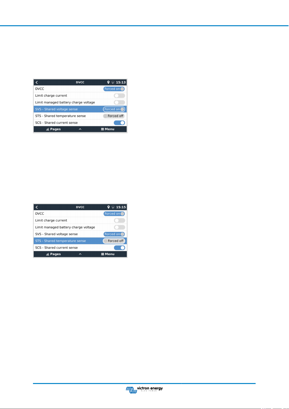
Ekrano GX Manual
This is what Limit managed battery charge voltage is designed for. Enabling this makes it possible to lower the maximum charge
voltage until cells have balanced.
Do not use it for any other purpose as it may have unwanted side effects, for example, balancing can fail or not start at all if the
charge voltage is set too low, causing the battery cells to become severely imbalanced over time. It is also not possible to set the
value above the charge voltage limit (CVL) sent by the battery.
11.4.3. Shared Voltage Sense (SVS)
Works with VE.Bus devices, VE.Direct and VE.Can MPPT solar chargers as well as Inverter RS and Multi RS.
The system automatically selects the best available voltage measurement. It will use the voltage from the BMS or a BMV battery
monitor, if possible, otherwise it will use the battery voltage reported by the VE.Bus system.
The voltage displayed on the GUI reflects the same voltage measurement.
Shared Voltage Sense (SVS) is by default enabled when DVCC is enabled. It can be disabled with a switch in Settings → DVCC.
SVS (and DVCC) is force enabled for the Lynx Smart BMS and cannot be changed.
Note that SVS is force-disabled for some batteries. Please see the compatibility page for your battery.
11.4.4. Shared Temperature Sense (STS)
Select the temperature sensor to use; and the GX device will send the measured battery temperature to the inverter/charger
system as well as all connected solar chargers.
Selectable sources for the battery temperature are:
• BMV-702 battery monitor
• BMV-712 battery monitor
• SmartShunt
• Lynx Shunt VE.Can battery monitors
• Multi/Quattro inverter/charger
• Solar chargers (if fitted with a temperature sensor)
Note that STS is forced disabled for the Lynx Smart BMS and some batteries. Please see the compatibility page for your battery.
Page 71
DVCC - Distributed Voltage and Current
Control
Page 78

Ekrano GX Manual
11.4.5. Shared Current Sense (SCS)
This feature forwards the battery current, as measured by a battery monitor connected to the GX device, to all connected solar
chargers.
The solar chargers can be configured to use the battery current for its tail current mechanism that ends absorption when the
current is below the configured threshold. For more information about that, refer to solar charger documentation.
This feature only applies to systems that are not ESS and/or don’t have a managed battery, since in both of those cases the
MPPT is already externally controlled.
Requires MPPT solar charger firmware v1.47 or newer.
11.4.6. Controlling BMS
For systems with multiple BMSs connected, this allows selection of which BMS to use for DVCC. This also allows the use of a
BMV or SmartShunt for SoC tracking by selecting a BMV as battery monitor (Settings → System setup) while the BMS is still
used for DVCC.
This setting is available in the Settings → DVCC menu on the GX device.
Page 72
DVCC - Distributed Voltage and Current
Control
Page 79

Ekrano GX Manual
11.5. DVCC features when using CAN-bus BMS battery
This chapter applies to all systems where an intelligent battery BMS is installed and connected via CAN-bus. Note that this does
not include the Victron VE.Bus BMS.
Such intelligent BMS sends the following parameters to the GX device:
1. Charge voltage limit (CVL): the maximum charge voltage that the battery currently accepts.
2. Charge current limit (CCL): the maximum charge current requested by the battery.
3. Discharge current limit (DCL): the maximum discharge current as requested by the battery.
For all three parameters, some types of batteries transmit dynamic values. For example they determine the maximum charge
voltage based on cell voltages, state of charge, or for example temperature. Other makes and brands use a fixed value.
For such batteries there is no need to wire allow to charge (ATC) and allow to discharge (ATD) connections to the AUX inputs of a
Multi or Quattro.
When inverting, i. e. in island mode, Multis and Quattros will shut down when the max discharge current is zero. They will
automatically start again as soon as either AC mains returns or when the BMS increases the max discharge current again.
See previous section Limit charge current [70], the user-configurable maximum charge current setting, for details about how the
Maximum charge current is used, how it prioritises solar and more.
All above means that setting up charge voltages or charge profiles in VEConfigure or VictronConnect is not necessary and
will also have no effect. The Multis, Quattros, Multi and Inverter RS and MPPT Solar Chargers will charge with the voltage as
received via CAN-bus from the battery. This also applies to systems with a Lynx Smart BMS connected to a GX device.
Page 73
DVCC - Distributed Voltage and Current
Control
Page 80

Ekrano GX Manual
11.6. DVCC for systems with the ESS Assistant
• The ESS Keep batteries charged mode will only work properly with DVCC enabled.
• A fixed solar offset of 0.4V (value for 48V system, divide by 4 for 12V) is applied when ESS-mode is set to Optimised in
combination with the Feed-in excess solar charger power-setting enabled, or when ESS-mode is set to Keep batteries charged.
• For system with ESS mode Optimised and Optimised (with BatteryLife): The system will automatically recharge the battery
(from the grid) when the SoC drops 5% or more below the value of ‘Minimum SoC’ in the ESS menu. Recharge stops when it
reaches the Minimum SoC.
• ESS status display in the graphic overview of the GX device and on VRM: In addition to the charge status (External Control or
Bulk/Absorption/Float), the following status can be displayed:
ESS status Meaning
#1 Low SoC: discharge disabled
#2 BatteryLife is active
#3 Charging disabled by BMS
#4 Discharging disabled by BMS
#5 Slow charge in progress (part of BatteryLife, see above)
#6 User configured a charge limit of zero
#7 User configured a discharge limit of zero
• Note: When DC-coupled PV feed-in excess is enabled with ESS, the DVCC system will not apply the DVCC charge current
limit from PV to battery. This behaviour is necessary to allow the export. Charge voltage limits will still apply.
Charge current limits set at the individual solar charger device settings level will also still apply.
• When the BMS is disconnected in an ESS system, solar chargers will stop and show error #67 – No BMS (see the MPPT Solar
Charger Error Codes for additional info).
Page 74
DVCC - Distributed Voltage and Current
Control
Page 81

Ekrano GX Manual
12. VRM Portal
12.1. VRM Portal introduction
When connected to the internet, a GX device can be used in combination with the Victron Remote Management (VRM) portal,
which enables:
• Easy remote access to all statistics and systems status online
• Remote Console on VRM [80]: access and configure your system as if you were standing besides it
• Remote Firmware update: Update the firmware of connected Solar Chargers and other Victron products
• Remote VEConfigure: Download and upload Remote VEConfigure files from and to the Multi/Quattro connected to your GX
device
• Remote Controls: Control devices such as the EV Charging Station, Inverter/charger, GX relay, Genset and ESS system
remotely via VRM
• Use of the VRM App for iOS and Android including VRM APP Widgets on your mobile device's homescreen
See the Internet Connectivity chapter [35] for how to connect the device to the internet.
For a complete overview of all features and functions of the VRM Portal, see the VRM Portal documentation.
12.2. Registering on VRM
Detailed instructions are in the VRM Portal Getting Started document.
Note that any system will need to first have been able to successfully send data to the VRM Portal. As long as there has been
no successful connection, it will not be possible to register the system to your VRM user account. In such case, refer to below
Troubleshooting data logging [77] and Remote Console on VRM - Troubleshooting [81] section.
12.3. Datalogging to VRM
Datalogs are transmitted to the VRM Portal over the Internet, if available. All related settings are available in the VRM Online
Portal menu (Device List → Settings → VRM online portal).
The transmission of the datalogs has been designed to work also on bad internet connections. Connections with up to 70%
permanent packet loss are still enough to get the data out, albeit partially delayed.
Adding an external storage device
When unable to transmit the logs, then the GX device will store them to non-volatile storage (ie. data is not lost on a power loss or
reboot).
Page 75 VRM Portal
Page 82

Ekrano GX Manual
The GX device has a buffer to store a couple of days worth of logs internally. To extend this period, insert a microSD card or USB
stick. You can see the internal storage status in the settings.
Note that, when inserting such storage device, any internally stored logs will automatically be transferred to the inserted stick: no
data is lost.
With or without an external storage device inserted, the GX device will always keep trying to connect to the portal and transmit
all backlogged logs. That means that even with months worth of backlog, once it re-acquires an Internet connection, all of the
backlog is sent out. The data is sent in a compressed manner: sending a lot of backlogged data will use considerably less
bandwidth than than sending the data with a continuously available internet connection.
Storage device requirements
• Supported file systems for MicroSD cards or USB flash drives are FAT (12, 16, 32), ext3, ext4 and exFAT.
• SD and SDHC type microSD cards of 32 GB capacity and smaller are sold containing FAT12, FAT16 or FAT32. They can be
used without a problem, unless they are subsequently re-formatted to an unsupported file system.
Manually transferring datalogs to VRM
For devices permanently without Internet, it is possible to take the data out, and then upload it manually from a laptop.
1. Go to Settings → VRM online portal, and click Eject the storage. Make sure to never just remove the SD-card/USB-stick, this
can lead to corruption and data loss.
2. Remove the storage device and insert it into a computer or laptop that is connected to the internet.
3. Open a webbrowser, and navigate to the VRM Portal.
4. Login and then navigate to the Installations menu:
5. Click the 'Upload GX file' option and follow instructions:
6. Remove the file from the storage device and re-insert it into the GX device. Note that uploading the same data twice does not
cause any problems; but still it is better not to do that.
With a log interval of once per minute, the required storage space roughly amounts to about 25 MB per month, depending on
the number of connected products. So with a 1 GB microSD card, you can store about 3 years of backlog. In other words, any
microSD card or USB stick should be sufficient to store the 6 months of data which VRM retains. When the storage device is full,
no more data will be logged.
If multiple storage devices are inserted, the GX device will store the data on the one inserted first. When that is removed, it
will not use the other one. Instead, it will create an internal backlog buffer. Only inserting a new one will make it switch to using
external storage again.
Network watchdog: auto-reboot
Page 76 VRM Portal
Page 83

Ekrano GX Manual
This feature, disabled by default, makes the GX device automatically reboot itself in case it has not been able to connect to the
VRM Portal.
12.4. Troubleshooting data logging
This chapter guides you through the troubleshooting that needs to be done when the GX device cannot transmit data to the VRM
portal.
Initial check
First, check whether there is a connection between the GX device and the VRM portal and whether data is being sent or not.
Don't worry if the GX device has lost connection to the Internet for a short time. The data logs that were not
transmitted during this time are temporarily stored in the GX device and will be transmitted once the Internet
connection is restored.
1. Check the 'Last contact' entry in the menu of the VRM online portal (Settings → VRM online portal → Last contact).
• If the displayed time is within the defined 'Log interval' setting in the same menu, this indicates that data is actively being
sent to VRM, which means everything is working properly.
• If it shows dashes, the GX device has been unable to contact the VRM Portal since it was powered up.
• If it shows a time, but an error is shown, then the GX device has been able to send data, but has since lost contact.
• If 'Logging enabled' is deactivated, then the GX device will not send any data to the VRM Portal.
2. Check the 'Stored records' entry in the same menu.
• The 'Stored records' indicates the number of logs that it has stored to send later.
• If this number is 0, it means that the Ekrano GX has sent all its data to the VRM Portal, which in turn means that the
connection is actually working.
• If this is larger than 0, it means that the Ekrano GX can not connect to the VRM Portal.
This is usually accompanied by an error message, which is described later in the chapter.
Page 77 VRM Portal
Page 84

Ekrano GX Manual
• If you continue to have issues with data logging, please read on.
The communication required to send data logs to the VRM Portal is:
1. A good working internet connection - Preferably use a wired connection via Ethernet cable. Tethered or hotspot
connections, e.g. with a cell phone, are unreliable and often interrupted or they do not automatically restore the connection
after it was lost.
2. A proper IP address - Normally the router takes care of this and assigns the IP address to connected devices/computers
automatically via DHCP as soon as you connect to them. A manual configuration is not necessary.
Outbound http(s) connection to http://ccgxlogging.victronenergy.com on port 80 and 443 - Note that should never be
3.
an issue, unless on very specialised company networks.
Note that the EGX does not support a proxy setup. For more details on the required networking, see the FAQ Q15: What type of
networking is used by the Ekrano GX (TCP and UDP ports)? [125].
Troubleshooting steps
1. Update the GX device to the latest available firmware
See the Firmware updates [58] chapter for details
2. Verify the network and internet connection
• Check if the network router has automatically assigned an IP address to the GX device in the Ethernet or
Wi-Fi menu (Settings → Ethernet → IP configuration → Automatic or Settings → Wi-Fi → Wi-Fi networks →
[Your_connected_WiFi_network] → IP configuration → Automatic). This also applies to manually configured IP addresses.
Make sure the following conditions are met:
• State must be ‘Connected’
• There must be an IP address that does not start with 169.
• There must be a Netmask
• There must be a Gateway
• There must be a DNS server
For a GX GSM or GX LTE 4G , see the Troubleshooting guide in the GX LTE 4G manual.
If the IP address starts with 169, check whether your network has a DHCP server running. 99% of all networks have a
DHCP server running, and it is enabled by default on all well-known ADSL, cable and 3G/4G routers. If there is no DHCP
server running, then configure the IP address manually as described in the Manual IP configuration [37] chapter.
• Ethernet
• When using Ethernet and 'State' shows 'Unplugged', verify that the Ethernet network cable is not faulty: try another one.
The two lights at the back of the EGX, where the Ethernet RJ45 cable plugs in, should be lit or blinking. Two dead lights
indicate a connection problem.
Page 78 VRM Portal
Page 85

Ekrano GX Manual
• WiFi
• When using WiFi and the menu shows 'No WiFi adapter connected', check the USB connection to the WiFi dongle. Try
to remove the dongle and insert it again.
• When using WiFi and the 'State' shows 'Failure', it might be that the WiFi password is incorrect. Press 'Forget network'
and try to connect again with the correct password.
3. Check the Connection error status
• Navigate to Settings → VRM online portal and check the 'Connection error' status:
• If a Connection error is shown, the EGX is not able to contact the VRM database. The connection error will show an error
code that indicates the nature of the connectivity problem. Also, details of the error message are shown, to facilitate on-site
IT experts to diagnose the problem.
• Error #150 Unexpected response text: The http/https call succeeded, but the response was incorrect. This indicates
that there is a WiFi or network login page, sometimes called a "captive portal", occasionally seen in Airports, Hotels,
Marinas or RV campgrounds. There is no solution to make the GX device work with a WiFi network that requires such a
login page and/or accepting of terms of use.
• Error #151 Unexpected HTTP Response: A connection succeeded, but the response did not indicate a successful
HTTP result code (normally 200). This might indicate that a transparent proxy is hijacking the connection. See #150
above for examples.
• Error #152 Connection time-out: this could indicate a poor-quality internet connection or a restrictive firewall.
• Error #153 Connection error: this could indicate a routing problem. For details, check the shown error message:
• Error #153 Connection problem, and then specifically an SSL related issue, such as in below screenshot: check the
date and time setting of the Gx Device, and also the time zone. And check that your router is not showing a special
disclaimer, login or acceptance page, like often seen in airports, hotels and other public wifi.
Page 79 VRM Portal
Page 86

Ekrano GX Manual
•
Error #154 DNS Failure: Make sure that a valid DNS server is configured in the Ethernet or WiFi menu. Typically this is
assigned automatically by a DHCP server in a network.
• Error #155 Routing error: VRM is unreachable. This error occurs if an ICMP error is received, indicating that no route
exists to the VRM server. Make sure your DHCP server assigns a working default route, or that the gateway is correctly
configured for static configurations.
• Error #159 Unknown error: This is a catch-all error for errors that cannot be directly categorised. In such cases the
error message will provide information about the problem.
12.5. Analysing data offline, without VRM
In certain cases, for example for very remote sites where there is no internet available, it can be useful to be able to analyse the
data without first having to upload it to the VRM Portal.
1. Install VictronConnect on a Windows or Apple laptop
2. Insert the storage device containing the log file(s)
3. Open VictronConnect and use the Venus Log Converter feature to convert them to Excel sheets. Note that the Venus Log
Converter is not available in the iOS and Android version of VictronConnect. See Importing and converting a GX Product
Family database File for more details in the VictronConnect manual.
12.6. Remote Console on VRM - Setup
This feature allows full remote control of a GX device over the internet:
Page 80 VRM Portal
Page 87

Ekrano GX Manual
Remote Console on VRM is disabled by default. Activate it by following these steps:
1. Enableg the feature in the Settings → Remote Console menu
For details see the The Remote Console menu [44] chapter.
2. Either set a password or disable the password
3. Restart the GX device.
Now the Remote Console option will appear in the menu on the VRM Portal. Click it to open the Remote Console:
12.7. Remote Console on VRM - Troubleshooting
Follow these steps to troubleshoot Remote Console on VRM:
1. Make sure that logging to the VRM portal works, see chapter Datalogging to VRM [75] and Troubleshooting data logging [77].
Without this; Remote Console on VRM will not work.
2. After enabling the Remote Console feature, make sure to set (or disable) the password.
3. Also make sure to restart the EGX after setting (or disabling) the password.
4. Make sure to update the EGX to the latest firmware version. The last stability improvement for Remote Console was made in
version v2.30.
5. After the restart, check the Remote Console on VRM status shows online or a port number. In case it says offline, or port
number 0, the EGX was unable to connect to the Remote Console server. This is normally caused by a (company) firewall,
blocking the connection. The solution is then to configure an exception rule in the firewall.
6. Verify that your web browser, on which you're using VRM, can access both of below URLs. Click both of the links to
check them. Note that seeing an Error means that all is OK. The good error is 'Error response, Error code 405, Method
Not Allowed'. If you get a timeout or another (browser) error, there may be a firewall blocking the connection. https://
vncrelay.victronenergy.com & https://vncrelay2.victronenergy.com/
Technical background
To have Remote Console on VRM working, your web browser and the GX device need to have a connection between them. This
connection is designed such that it doesn't need any special configuration or opening up of firewalls in almost all situations. The
0.1% of situations where it doesn't work out of the box are, for example, large corporate networks with special security, or long
range expensive satellite or radio supported networks, such as seen in rural areas of Africa and other remote areas.
When Remote Console on VRM is enabled, the GX device will open and maintain a connection to any of the servers
pointed to by supporthosts.victronenergy.com. Which currently resolves to multiple IP addresses (84.22.108.49, 84.22.107.120,
3.25.10.245, 13.244.154.199 or 35.165.124.40, depending on where you are), and likely more in the future. The technology used
is SSH, and it will try to connect using port 22, 80 and 443, only one of them needs to work. The reason for it to try all three is that
on most networks at least one of them will be allowed by the local firewall.
Once connected to one of the supporthost servers, that reverse SSH tunnel is waiting to be connected from someone needing
the connection. Which can be your browser, or a Victron engineer since this same technology is used for the Remote Support
functionality; for more information see above.
Page 81 VRM Portal
Page 88

Ekrano GX Manual
When using Remote Console on VRM, the browser will connect to either vncrelay.victronenergy.com, or
vncrelay2.victronenergy.com, using websockets on port 443. For more details of used connections by the GX device, see Q15 of
the FAQ [125].
Page 82 VRM Portal
Page 89

Ekrano GX Manual
13. Marine MFD integration by App
13.1. Introduction & requirements
A Glass Bridge is a MFD (Multi-Function Display) that integrates a boat’s systems and navigation status into a large screen or
screens at the helm of the vessel, so doing away with multiple gauges, brackets and wiring complications.
A Victron system can be easily integrated into a MFD as can be seen in this video:
Functionalities:
• Monitor shore power and generator status.
• Monitor battery status for one or more batteries. By using the voltage of for example battery chargers, it can also visualise
secondary batteries such as Generator starter batteries.
• Monitor the power conversion equipment: chargers, inverters, inverter/chargers.
• Monitor solar production from an MPPT Solar Charger.
• Monitor AC loads, and DC loads.
• Control shore power input current limit.
• Control the inverter/charger: switch it off, on, or set it to charger-only.
• Optionally open the Victron Remote Console panel; allowing access to further parameters.
Please note that monitoring and control of AC chargers connected via VE.Direct or VE.Can (this applies to Phoenix IP43 Smart
Chargers and the Skylla series) only works when shore power is connected.
Victron equipment compatibility:
• All Victron inverter/chargers: From a 500VA single-phase device up to a large 180kVA three-phase-system, including Multis,
Quattros, 230VAC and 120VAC models.
• Battery Monitors: BMV-700, BMV-702, BMV-712, SmartShunt, and newer, Lynx Shunt VE.Can, Lynx Ion BMS, Lynx Smart BMS
• All Victron MPPT Solar Charge Controllers
Required components:
• Battery system
• Victron GX device (all models are compatible)
• Victron Inverter/charger
Page 83 Marine MFD integration by App
Page 90

Ekrano GX Manual
• Victron Battery monitor
• Ethernet network cable connected between MFD and the GX device
• MFD specific ethernet adapter cable (only for some brands, see detailed information in below links)
Using the App for other purposes
The app as visible on the MFDs is a HTML5 app hosted on the GX device. It can also be accessed from a regular PC (or mobile
device) by navigating a browser to: http://venus.local/app/, or replace venus.local with the GX IP address.
13.2. Raymarine MFD Integration
13.2.1. Introduction
This chapter explains how to connect to Raymarine MFDs using an Ethernet connection. Also, the last chapter explains the
Raymarine specifics when connecting on NMEA 2000.
The integration technology used is called LightHouse Apps by Raymarine.
Note that there is an alternative method to connect, which is NMEA 2000. For details see the Marine MFD integration by NMEA
2000 [95] chapter.
13.2.2. Compatibility
The MFD integration is compatible with the Axiom, Axiom Pro and Axiom XL MFDs running on LightHouse 3 and Lighthouse 4.
The multifunction displays of the eS and gS series that have been upgraded to LightHouse 3 are not compatible.
Raymarine MFDs need at least LightHouse v3.11 for compatibility, which was released in November 2019.
From Victron side, all GX devices (Cerbo GX, Color Control GX, Venus GX, and so forth) can be used and are compatible. For
details on detailed product compatibility with regarding to inverter/chargers and other components, see the main Marine MFD
Integration by App [83] chapter.
13.2.3. Wiring
The MFD needs to be connected to the GX device using ethernet. It is not possible to connect over WiFi. For the ethernet
connection, a RayNet adapter is required.
The RayNet adapters can be purchased from Raymarine:
Raymarine part number Description
A62360 RayNet (F) to RJ45 (M) - 1m
A80151 RayNet (F) to RJ45 (M) - 3m
A80159 RayNet (F) to RJ45 (M) - 10m
A80247 RayNet (F) to RJ45 (F) Adapter
A80513 RayNet male to RJ45 adaptor cable
To connect the GX device to the internet as well, use WiFi. If the Axiom MFD is connected to internet (using WiFi), it will
automatically share its connection with the GX device over ethernet.
Connecting a Axiom MFD to a network router over Ethernet leads to IP address conflicts, due to the integrated
DHCP server in the Axiom MFD.
It is not possible to use a GX GSM or GX LTE 4G, due to the integrated DHCP server in the Axiom MFD.
As of Raymarine LightHouse v3.15, there is an option to toggle DHCP. Disabling this option does not mean
that the Axiom MFD will work with third party network routers. See this post on Victron Community for more
information.
13.2.4. GX device configuration
1. On the Victron GX device, go to Settings → Services, and there enable both MQTT on LAN (SSL) and MQTT
on LAN (Plaintext).
Page 84 Marine MFD integration by App
Page 91

Ekrano GX Manual
2. Next, go to Menu → Settings → System Setup → Battery Measurements, and there set up what batteries you want to see on
the MFD; and by what name.
3. For boats, RVs and other applications with DC loads such as lighting and a Battery Monitor installed, make sure to enable the
“Has DC system setting”. For more information about it, see the Menu structure and configurable parameters [45] chapter.
No other settings such as IP addresses or similar are required, since the Axiom MFDs have an integrated DHCP server.
13.2.5. Configuring multiple battery measurements
This video explains how to set up multiple battery measurements and how to name them.
13.2.6. Installation step-by-step
1. Connect the RayNet adapter cable to the MFD
2. Connect the RJ45 end of the RayNet adapter cable to the Ethernet port of the GX device
3. On the MFD go to Apps and then select the Victron logo
4. And...you're done. All information can now be viewed on one screen, which is:
DC loads, Battery information, Shore power connection, Solar production, AC loads, Inverter and Generator control and the
option to open the Remote Console
This video shows the exact steps:
Page 85 Marine MFD integration by App
Page 92

Ekrano GX Manual
After connecting the Ethernet cable the GX device, it receives an IP number from the Axiom DHCP. If you start
the Victron App on the Axiom and it shows “hardware devices not found”, just restart the Axiom and see… it
works!
13.2.7. NMEA 2000
Besides connecting over ethernet, a Raymarine MFD can also be connected to the Victron system using NMEA 2000. If you’re
new to NMEA 2000 & Victron, start with reading the Marine MFD integration by NMEA 2000 [95] chapter.
The below sections explain the specifics of NMEA 2000 when connecting Victron to a Raymarine MFD.
13.2.8. Generic and supported PGNs
To setup the data sources on the Raymarine, go to Settings > Network > Sources > Advanced.
If you have more than 1 battery be sure to adjust the settings of the Axiom to the correct amount of battery(banks).
The following Victron related PGNs are supported by Raymarine:
PGN Description
127505 Fluid level (tank levels)
127506 DC Detailed Status (State-of-charge, Time-to-go)
127507 Charger status
127508 Battery Status (Battery Voltage, Battery Current)
127509 Inverter status
Note that J1939 - AC data is not supported by Raymarine.
When the NMEA 2000/STNG network has GPS data, the GX device sees this as a GPS source and is able to use the GPS
position in VRM.
13.2.9. Instancing requirements when using Raymarine
Fluid instancing details:
• Raymarine i70: max number of tank levels is 5; fluid instance 0-4 and type must be fuel
• Raymarine i70s: max number of tank levels is 5; fluid instance 0-4 and type must be fuel
• Axiom MFDs: per Lighthouse version 4.1.75, a maximum of 16 tanks can be connected; fluid instance 0-15
13.2.10. Before LightHouse 4.1.75
If there is more than one ie. SmartShunt in the NMEA 2000 network, or a solar charger and a SmartShunt, or any other device
transmitting the same type of PGNs, then the Data instances of these PGNs must be changed to make each Data instance
unique.
Typically this concerns the Battery instance, used in the Battery Status and DC Detailed PGNs.
See here for how to do that: Changing NMEA 2000 Instances, section Data instances. This requires an Actisense NGT-1 NMEA
2000 to PC (USB) Interface.
Page 86 Marine MFD integration by App
Page 93
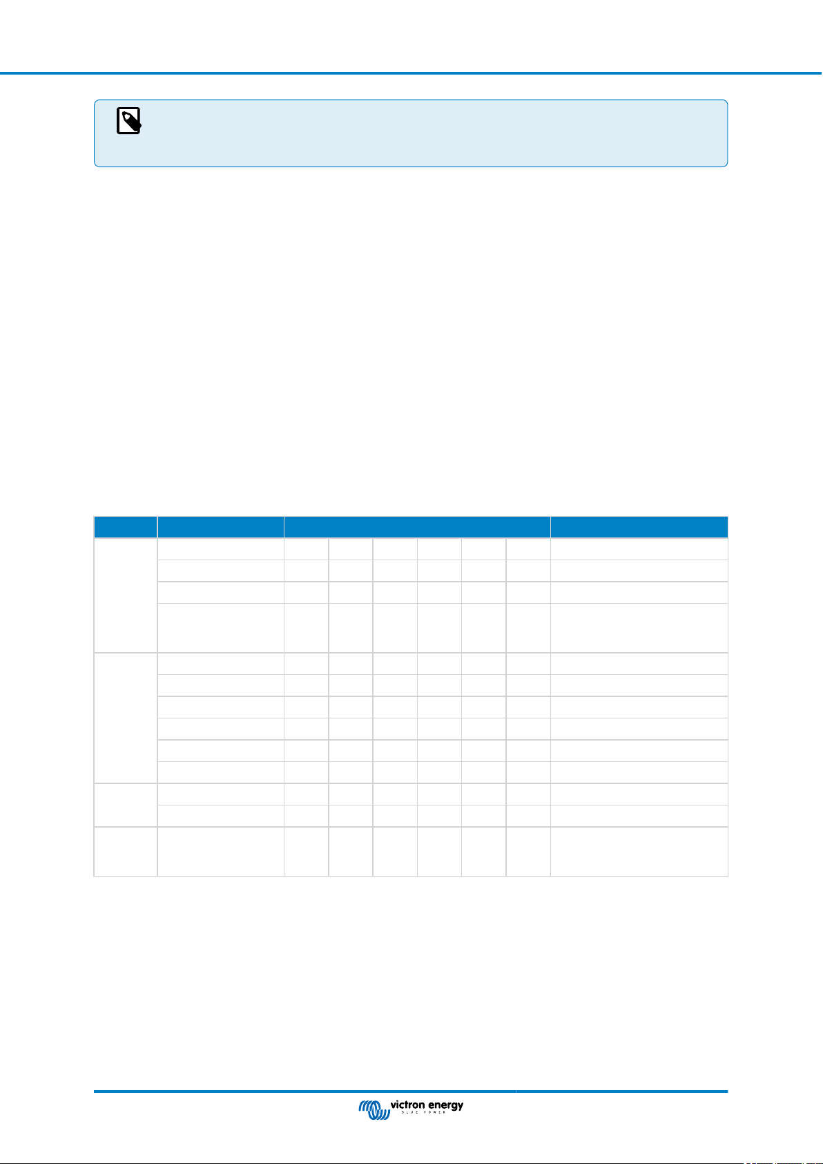
Ekrano GX Manual
This requirement of Data instances being globally unique for a PGN is specific to Raymarine. Other brands
do not require this. And, although perhaps besides the point, also the NMEA 2000 standard does not require
it. More specifically, it says: “Data instances shall be unique in the same PGNs transmitted by a device. Data
instances shall not be globally unique on the network."
13.2.11. LightHouse 4.1.75 and newer
As of LightHouse version 4.1.75, the battery instances no longer need to be unique. This means that you can leave the battery
instance to its default value, which is typically set to 0. The batteries are automatically detected by the Axiom display.
13.3. Navico MFD Integration
13.3.1. Introduction
Navico is the overall brand behind the B&G, Simrad and Lowrance MFDs.
This chapter explains how to connect to Navico MFDs using an Ethernet connection.
Make sure to also study the Marine MFD Integration by App [83] chapter.
Note that there is an alternative method to connect, which is NMEA 2000. For details see the Marine MFD integration by NMEA
2000 [95] chapter.
13.3.2. Compatibility
Navico compatible hardware:
Product Display Size Remarks
Simrad NSO EVO3 16 19 24
NSO EVO2 16 19 24
NSS EVO3 7 9 12 16
Go 7* 9 12
B&G Zeus3 Glass Helm 16 19 24
3
Zeus
Zeus S 7 9 12
Zeus 3S 9 12 16
Zeus 3S Glass Helm 16 19 24
Vulcan 7 9 12
LowranceHDS Live 7 9 12 16
HDS Carbon 7 9 12 16
Inform
ation
Display
IDS 9 12
7 9 12 16
5 is not compatible to Ethernet
port *Go7 YSE not compatible
= only Go7 XSR
Note that this feature also works on the Simrad NSS evo2 and B&G Zeus2, but only limited. Furthermore, it is not officially
supported by Victron or Navico, and there will be no new software versions to fix any problems that may arise.. In other words, it
is not a supported configuration by Navico but the consumer can feel free to use it (if they contact Navico or Victron service, our
team will tell them it is not a supported configuration). More testing and user feedback will have to show what does and what does
not work on the evo2/Zeus2.
At the moment it is not possible to control the Victron MFD App other than via the touch screen. This means that you cannot use:
• Local controls, i.e. WheelKey and arrow keys
• Simrad OP50
• B&G ZC2
Page 87 Marine MFD integration by App
Page 94

Ekrano GX Manual
13.3.3. Wiring
The Navico device needs to be connected to the GX device using Ethernet. Its not possible to connect over WiFi. For the
Ethernet connection, a Navico adapter is required as the Navico MFDs feature a round water proof connector on the back. The
adapters can be purchased from Navico:
• ETHADAPT-2M 127-56
• CABLE RJ45M-5F ETH ADPTR NONWATERPRF
13.3.4. GX device configuration
1. On the Victron GX device, go to Settings → Services, and there enable both MQTT on LAN (SSL) and MQTT
on LAN (Plaintext).
2. Next, go to Menu → Settings → System Setup → Battery Measurements, and there set up what batteries you want to see on
the MFD; and by what name.
3. For boats, RVs and other applications with DC loads such as lighting and a Battery Monitor installed, make sure to enable the
“Has DC system setting”. For more information about it, see the Menu structure and configurable parameters [45] chapter.
No other settings such as IP addresses or similar are required. The GX device and the Navico devices connect to each other
using a technology called linklocal addressing.
It is possible to connect the router to the same LAN; and that way connect the GX device to the internet. The GX device can also
be connected to the internet via WiFi or with a GX LTE 4G.
Note that the GX LTE 4G can only be used if the MFD and GX device are directly connected to each other, without a router.
13.3.5. Configuring multiple battery measurements
This video explains how to set up multiple battery measurements and how to name them.
Page 88 Marine MFD integration by App
Page 95

Ekrano GX Manual
13.3.6. Installation step-by-step
1. Connect the UTP cable to the MFD
2. Connect the other end of the UTP cable to the Ethernet port of the GX device
3. Go to Apps on the MFD and then select the Victron Energy logo, which will appear after a few seconds
4. And...you're done. All information can now be viewed on one screen, which is:
DC loads, Battery information, Shore power connection, Solar production, AC loads, Inverter and Generator control and the
option to open the Remote Console
This video shows the exact steps:
13.3.7. NMEA 2000
Besides connecting over ethernet, a Navico MFD can also be connected to the Victron system using NMEA 2000. If you’re new to
NMEA 2000 & Victron, start with reading the Marine MFD integration by NMEA 2000 [95] chapter.
The MFD can be configured easily to display the data from the GX device. There is no need to change any instance.
To setup the data sources on the MFD, go to Settings > Network > Sources > Advanced.
13.3.8. Generic and supported PGNs
To setup the data sources on the Navico MFD, go to Settings > Network > Sources > Advanced.
The following Victron related PGNs are supported:
PGN Description
127505 Fluid level (tanks)
127506 DC Detailed Status (State-of-charge, Time-to-go)
127507 Charger status
127508 Battery Status (Battery Voltage, Battery Current)
127509 Inverter status
J1939 AC PGNs
13.3.9. Troubleshooting
Q1: The MFD page shows outdated information or shows the connection issue page, but the GX device is running and connected
and the Victron icon is present on the home page.
A1: Try reloading the page by pressing the menu on the top right corner and select HOME.
Page 89 Marine MFD integration by App
Page 96

Ekrano GX Manual
13.4. Garmin MFD Integration
13.4.1. Introduction
This chapter explains how to connect to Garmin MFDs using an Ethernet connection. The integration technology used is
called Garmin OneHelm.
Make sure to also study the Marine MFD Integration by App [83] chapter.
Note that there is an alternative method to connect, which is NMEA 2000. For details see the Marine MFD integration by NMEA
2000 [95] chapter.
13.4.2. Compatibility
OneHelm is currently available for the following models:
• GPSMAP® 8400/8600 MFD series
• GPSMAP® 722/922/1222 Plus MFD series
ActiveCaptain is also supported. The screenshot below shows ActiveCaptain with the Victron App.
From Victron side, all GX devices (Cerbo GX, Color Control GX, Venus GX, and so forth) can be used and are compatible. For
details on detailed product compatibility with regarding to inverter/chargers and other components, see the main Marine MFD
Integration by App [83] chapter.
13.4.3. Wiring
The Garmin MFD needs to be connected to the GX device using Ethernet. Its not possible to connect over WiFi. For the Ethernet
connection, a Garmin adapter is required:
Garmin part name Length Garmin part number
Marine Network Cables 6ft 010-10550-00
Marine Network Cables 20ft 010-10551-00
Marine Network Cables 40ft 010-10552-00
Marine Network Cables 500ft 010-10647-01
13.4.4. GX device configuration
1. On the Victron GX device, go to Settings → Services, and there enable both MQTT on LAN (SSL) and MQTT
on LAN (Plaintext).
Page 90 Marine MFD integration by App
Page 97

Ekrano GX Manual
2. Next, go to Menu → Settings → System Setup → Battery Measurements, and there set up what batteries you want to see on
the MFD; and by what name.
3. For boats, RVs and other applications with DC loads such as lighting and a Battery Monitor installed, make sure to enable the
“Has DC system setting”. For more information about it, see the Menu structure and configurable parameters [45] chapter.
No special networking settings are necessary. Not on the Garmin; and not on the Victron GX device.
The Garmin MFDs run a DHCP server; and the GX device are by default configured to use DHCP. After plugging in the cable, the
Victron Energy icon will show up after 10 to 30 seconds.
To connect the GX device to the internet and the VRM Portal while its Ethernet port is already in use to connect to the Garmin,
use WiFi. For more information about it, see the Internet connectivity [35] chapter.
Connecting a Garmin MFD to a network router over Ethernet leads to IP address conflicts, due to the
integrated DHCP server.
It is not possible to use a GX GSM or a GX LTE 4G due to the integrated DHCP server of the Garmin MFD.
13.4.5. Configuring multiple battery measurements
This video explains how to set up multiple battery measurements and how to name them.
13.4.6. Installation step-by-step
1. Connect the UTP cable to the MFD
Page 91 Marine MFD integration by App
Page 98

Ekrano GX Manual
2. Connect the other end of the UTP cable to the Ethernet port of the GX device
3. Go to Apps on the MFD and then select the Victron Energy logo, which will appear after a few seconds
4. And...you're done. All information can now be viewed on one screen, which is:
DC loads, Battery information, Shore power connection, Solar production, AC loads, Inverter and Generator control and the
option to open the Remote Console
This video shows the exact steps:
13.4.7. NMEA 2000
Besides connecting over ethernet, a Garmin MFD can also be connected to the Victron system using NMEA 2000. If you’re new
to NMEA 2000 & Victron, start with reading the Marine MFD integration by NMEA 2000 [95] chapter.
The MFD can be configured easily to display the data from the GX device. There is no need to change any instance.
To setup NMEA 2000 on the MFD, go to Settings > Communications > NMEA 2000 Setup > Device List. Here you can view
information about the connected products and change their names. Note that the names are stored on the MFD and not on the
NMEA 2000 device.
13.4.8. Generic and supported PGNs
The following Victron related PGNs are supported:
PGN Description
127505 Fluid level (tanks)
127506 DC Detailed Status (State-of-charge, Time-to-go)
127508 Battery Status (Battery Voltage, Battery Current)
The supported PGNs may vary per model. Please consult the manual of the MFD for a list of supported PGNs.
13.5. Furuno MFD Integration
13.5.1. Introduction
This chapter explains how to connect to Furuno MFDs using an Ethernet connection.
Make sure to also study the Marine MFD Integration by App [83] chapter.
Note that there is an alternative method to connect, which is NMEA 2000. For details see the Marine MFD integration by NMEA
2000 [95] chapter. Currently, Furuno MFDs only have support for fluid level PGNs sent out by Victron equipment.
13.5.2. Compatibility
The MFD integration is compatible with the following Furuno MFDs:
• NavNet TZtouch3 TZT12F
• NavNet TZtouch3 TZT16F
• NavNet TZtouch3 TZT19F
Page 92 Marine MFD integration by App
Page 99

Ekrano GX Manual
• Navnet TZtouch2 TZT2BB Black box
Note that NavNet TZtouch3 MFDs need at least software version v1.08. The Navnet TZtouch2 TZT2BB needs at least software
version v7.01.
Also note that the Navnet TZtouch2 TZTL models are not supported.
From Victron side, all GX devices (Cerbo GX, Color Control GX, Venus GX, and so forth) can be used and are compatible. For
details on detailed product compatibility with regarding to inverter/chargers and other components, see the main Marine MFD
Integration by App [83] chapter.
13.5.3. Wiring
The Furuno device needs to be connected to the GX device using Ethernet. Its not possible to connect over WiFi. For the
Ethernet connection, a standard Ethernet cable can be used. The GX device can either be connected directly to the MFD or
through a network router/switch.
13.5.4. Configuration
Ethernet configuration
On the Victron GX device, make sure that the Ethernet cable is connected and then go to Settings → Ethernet and set the
following configuration:
Setting Value
IP configuration Manual
IP address 172.31.201.12
Netmask 255.255.0.0
Gateway 0.0.0.0 or the IP address of the router in your network
DNS Server 0.0.0.0 or the IP address of the router in your network
It is possible to connect a router to the same LAN; and that way connect the GX device to the internet. Make sure
the Gateway and DNS Server settings of the GX are set to the IP address of the router, and that the router has its LAN IP
addressing configured in the same subnet.
It is not possible to use a GX GSM or a GX LTE 4G.
GX device configuration
1. On the Victron GX device, go to Settings → Services, and there enable both MQTT on LAN (SSL) and MQTT
on LAN (Plaintext).
Page 93 Marine MFD integration by App
Page 100

Ekrano GX Manual
2. Next, go to Menu → Settings → System Setup → Battery Measurements, and there set up what batteries you want to see on
the MFD; and by what name.
3. For boats, RVs and other applications with DC loads such as lighting and a Battery Monitor installed, make sure to enable the
“Has DC system setting”. For more information about it, see the Menu structure and configurable parameters [45] chapter.
13.5.5. Configuring multiple battery measurements
This video explains how to set up multiple battery measurements and how to name them.
13.5.6. NMEA 2000
Besides connecting over ethernet, a Furuno MFD can also be connected to the Victron system using NMEA 2000. If you’re new to
NMEA 2000 & Victron, start with reading the Marine MFD integration by NMEA 2000 [95] chapter.
This chapter documents the specifics when displaying Victron NMEA 2000 information on Furuno MFDs. Note that this is not
meant to be an extensive guide. It's the simple result of our R&D checking everything on a Furuno MFD. The functionality is
(mostly) dictated by Furuno software and may therefore also change and improve when Furuno company changes their software.
The MFD can be configured easily to display the data from the GX device. To display tank data, there is no need to change any
instance. In order to properly display Battery/DC data from Victron equipment, you need to change the Data instances of the
PGNs that are sent out. See here for how to do that: Changing NMEA 2000 Instances, section Data instances.
To view NMEA 2000 devices on the MFD, go to Settings > Initial Setup > Data Aquisition > Sensor List. Here you can view basic
information and change Device instances and custom names.
13.5.7. Generic and supported PGNs
The following Victron related PGNs are supported:
PGN Description
127505 Fluid level (tanks)
127506 DC Detailed Status (State-of-charge, Time-to-go)
127508 Battery Status (limited support); Voltage, Current
1)
The tested Furuno MFD firmware supports a maximum of 4 batteries, no more
2)
Due to a bug in the MFD firmware, a negative battery current (ie. when discharging) is shown as --- (three dashes)
1)
(1, 2)
Page 94 Marine MFD integration by App
 Loading...