

Page 1

Manual
Handleiding
Manuel
Anleitung
Manual
Battery Monitor
EN
NL
FR
DE
ES
BMV-700
BMV-700H
BMV-702
BMV-712 Smart
SE
Användarhandbok
Appendix
Appendix
Page 2

Page 3

1 QUICK START GUIDE
1.1 Battery capacity
1.2 Auxiliary input (BMV-702 and BMV-712 Smart only)
1.3 Important combined button functions
2 NORMAL OPERATING MODE
2.1 Read-out overview
2.2 Synchronising the BMV
2.3 Common problems
3 FEATURES AND FUNCTIONALITY
3.1 Features of the three BMV models
3.2 Why should I monitor my battery?
3.3 How does the BMV work?
3.3.1 About battery capacity and the rate of discharge
3.3.2 About charge efficiency (CEF)
3.4 Several battery state of charge display options
3.5 History data
3.6 Use of alternative shunts
3.7 Automatic detection of nominal system voltage
3.8 Alarm, buzzer and relay
3.9 Interface options
3.9.1 PC Software
3.9.2 Large display and remote monitoring
3.9.3 Custom integration (programming required)
3.10 Additional functionality of the BMV-702 and BMV-712 Smart
3.10.1 Auxiliary battery monitoring
3.10.2 Battery temperature monitoring
3.10.3 Midpoint voltage monitoring
3.11 Additional functionality of the BMV-712 Smart
3.11.1 Automatic cycling through status-items
3.11.2 Turning Bluetooth On/Off
4 FULL SETUP DETAILS
4.1 Using the menus
4.2 Function overview
4.2.1 Battery settings
4.2.2 Relay settings
4.2.3 Alarm-Buzzer settings
4.2.4 Display settings
4.2.5 Miscellaneous
4.3 History data
5 MORE ABOUT PEUKERT’S FORMULA AND MIDPOINT MONITORING
6 LITHIUM IRON PHOSPHATE BATTERIES (LiFePO4)
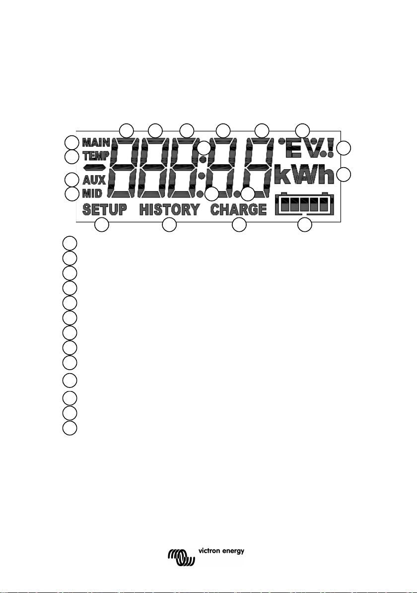
7 DISPLAY
8 TECHNICAL DATA
1
EN NL FR DE ES SE Appendix
NL FR DE ES SE IT PT
Page 4

Safety Precautions
Transport and storage
• Working in the vicinity of a lead acid battery is
dangerous. Batteries can generate explosive gases
during operation. Never smoke or allow a spark or flame
in the vicinity of a battery. Provide sufficient ventilation
around the battery.
• Wear eye and clothing protection. Avoid touching eyes
while working near batteries. Wash your hands when
done.
• If battery acid contacts skin or clothing, wash them
immediately with soap and water. If acid enters an eye,
immediately flood the eye with running cold water for at
least 15 minutes and get medical attention immediately.
• Be careful when using metal tools in the vicinity of
batteries. Dropping a metal tool onto a battery might
cause a short circuit and possibly an explosion.
• Remove personal metal items such as rings, bracelets,
necklaces, and watches when working with a battery. A
battery can produce a short circuit current high enough
to melt objects such as rings, causing severe burns.
• Store the product in a dry environment.
• Storage temperature: -40 °C to +60 °C
2
Page 5

1 QUICK START GUIDE
This quick start guide assumes that the BMV is being installed for the first
time, or that factory settings have been restored.
Please see the appendix at the end of this manual for wiring suggestions.
The factory settings are suitable for the average lead acid battery:
flooded, GEL or AGM.
The BMV will automatically detect the nominal voltage of the battery
system immediately after completion of the setup wizard (for details and
limitations of automatic nominal voltage detection, see section 3.8).
Therefore the only settings which need to be made are the battery capacity
(BMV-700 and BMV-700H), and the functionality of the auxiliary input
(BMV-702 and BMV-712).
Please install the BMV in accordance with the quick installation guide.
After inserting the fuse in the positive supply cable to the main battery, the
BMV will automatically start the setup wizard.
The setup wizard below must be completed before other settings can be
made. Alternatively, use the VictronConnect app and a smart phone.
Remarks:
a) In case of solar applications or Li-ion batteries several settings may
have to be changed. Please refer to section 2.3 resp. section 6. The setup
wizard below must be completed before other settings can be made.
b) When using a shunt other than the one supplied with the BMV,
please refer to section 3.6. The setup wizard below must be completed
before other settings can be made.
c) Bluetooth
Use a Bluetooth Smart enabled device (smart phone or tablet) for easy
and fast initial setup, for changing settings and for real time monitoring.
BMV-700 or -702: VE.Direct Bluetooth Smart dongle needed.
BMV-712 Smart: Bluetooth enabled, no dongle needed. Ultra low current
draw.
EN NL FR DE ES SE Appendix
NL FR DE ES SE IT PT
3
Page 6

Bluetooth:
VE.Direct Bluetooth Smart dongle: see the manual on our website
VE.Direct Bluetooth Smart dongle
BMV-712 Smart:
Download the VictronConnect app (see Downloads on our website)
VictronConnect manual
Pairing procedure: the default PIN code is 000000
After connecting, the PIN code can be changed by pressing the (i) button in
the top right of the app.
If the dongle PIN code is lost, reset it to 000000 by pressing and holding
the clear PIN button until the solid blue colored Bluetooth light flashes off
and on momentarily.
4
Page 7

Setup wizard (alternatively, use the VictronConnect app and smart phone):
1.1 Battery capacity (preferably use the 20 hour capacity rating (C
20))
a) After inserting the fuse the display will show the scrolling text
If this text is not shown, press SETUP and SELECT simultaneously during
3 seconds to restore factory settings or go to section 4 for full setup details
(setting 64, Lock setup, must be OFF to restore factory settings, see
section 4.2.5).
b) Press any button to stop scrolling and the factory default value
will appear in edit mode: the first digit will blink.
Enter the desired value with the + and – buttons.
c) Press SELECT to set the next digit in the same manner.
Repeat this procedure until the required battery capacity is displayed.
The capacity is automatically stored in non-volatile memory when the last
digit has been set by pressing SELECT. This is indicated with a short
beep.
If a correction has to be made, press SELECT again and repeat the
procedure.
d) BMV-700 and 700H: press SETUP or + or – to end the setup wizard and
switch to normal operating mode.
BMV-702: press SETUP or + or – to proceed to auxiliary input setting.
1.2 Auxiliary input (BMV-702 and -712 only)
a) The display will show
scrolling.
b) Press SELECT to stop scrolling and the LCD will show:
Use the + or – key to select the required function of the auxiliary input:
for monitoring the starter battery voltage.
for monitoring the midpoint voltage of a battery bank.
for using the optional temperature sensor
Press SELECT to confirm. Confirmation is indicated with a short beep.
c) Press SETUP or + or – to end the setup wizard and switch to normal
operating mode.
EN NL FR DE ES SE Appendix
NL FR DE ES SE IT PT
5
Page 8

The BMV is now ready for use.
When powered up for the first time, the BMV will by default display 100 %
state of charge. See section 4.2.1, setting 70 to change this this
behaviour.
When in normal mode the backlight of the BMV switches off after no key
has been pressed for 60 seconds. Press any key to restore backlight.
The cable with integrated temperature sensor has to be purchased
separately (part no: ASS000100000). This temperature sensor is not
interchangeable with other Victron temperature sensors, as used with
Multis/Quattros or battery chargers.
1.3 Important combined button functions
(see also section 4.1: using the menus)
a) Restore factory settings
Press and hold SETUP and SELECT simultaneously for 3 seconds
b) Manual synchronisation
Press and hold the up and down buttons simultaneously for 3 seconds
c) Silence audible alarm
An alarm is acknowledged when any button is pressed. However, the
alarm icon is displayed as long as the alarm condition remains.
1.4 Realtime data displayed on a smartphone
With the VE.Direct Bluetooth Smart dongle realtime data and alarms can
be displayed on Apple and Android smartphones, tablets and other
devices.
Note:
A VE.Direct Bluetooth Smart dongle is not required for BMV-712, since it
has Bluetooth built-in.
6
Page 9
2 NORMAL OPERATING MODE
2.1 Readout overview
In normal operating mode the BMV displays an overview of important
parameters.
The + and – selection buttons give access to various readouts:
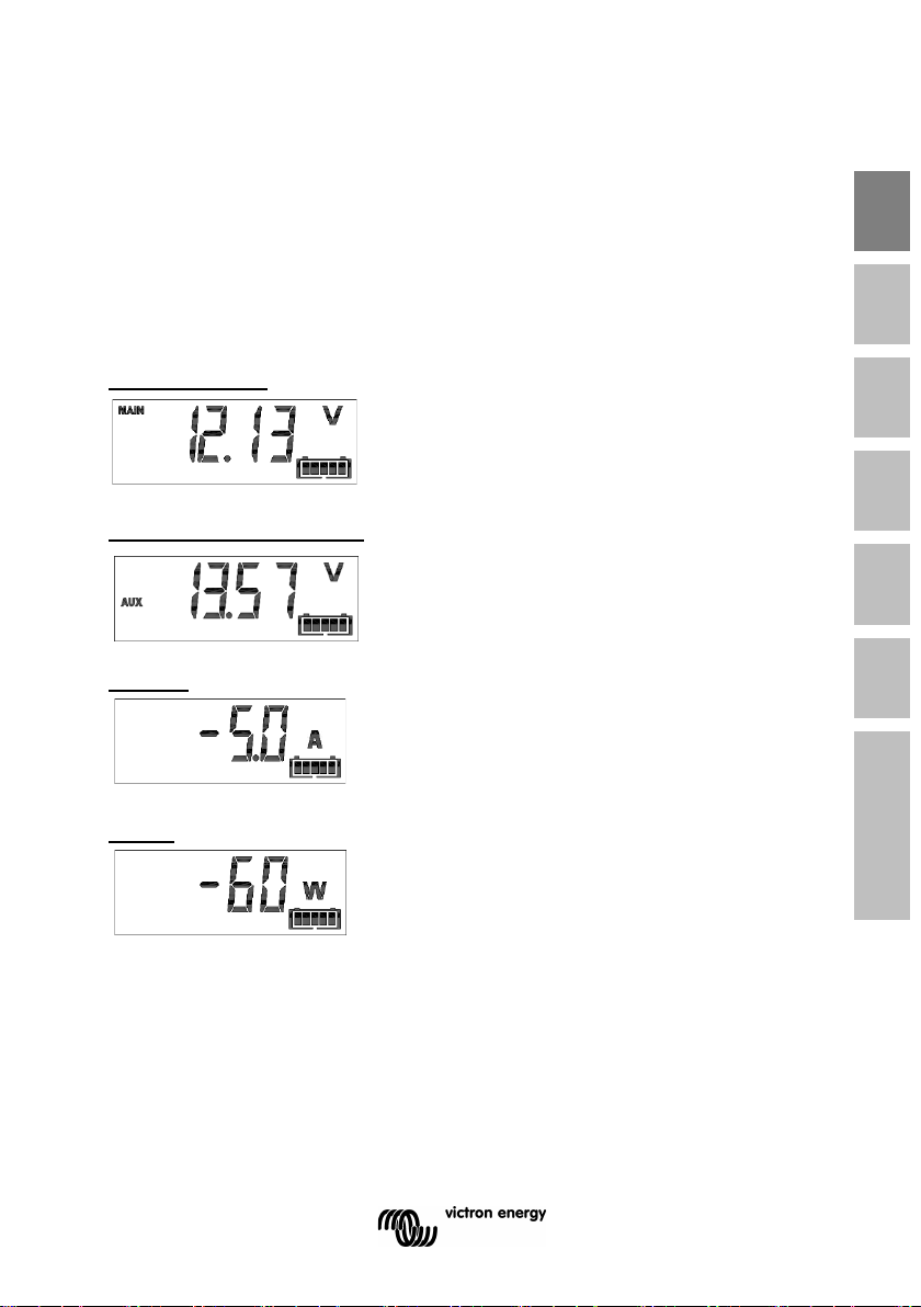
Battery voltage
Auxiliary battery voltage
BMV-702 and -712 only, when the auxiliary
input is set to START.
Current
The actual current flowing out of the battery
(negative sign) or into the battery (no sign).
Power
The power drawn from the battery (negative
sign) or flowing into the battery (no sign).
EN NL FR DE ES SE Appendix
NL FR DE ES SE IT PT
7
Page 10

Consumed Amp-hours
The amount of Ah consumed from the
battery
Example:
If a current of 12 A is drawn from a fully charged battery for a period of 3
hours, this readout will show -36.0 Ah.
(-12 x 3 = -36)
Note:
Three dashes ‘---’ will be shown when the BMV is started in
unsynchronised state. See section 4.2.1, setting number 70.
State of charge
A fully charged battery will be indicated by a
value of 100.0 %. A fully discharged battery
will be indicated by a value of 0.0 %.
Note:
Three dashes ‘---’ will be shown when the BMV is started in
unsynchronised state. See section 4.2.1, setting number 70.
Time-to-go
An estimation of how long the battery can
support the present load until it needs
recharging.
The time-to-go displayed is the time to reach the discharge floor.
See 4.2.2, setting number 16.
Note:
Three dashes ‘---’ will be shown when the BMV is started in
unsynchronised state. See section 4.2.1, setting number 70.
8
Page 11

Battery temperature
BMV-702 and -712 only, when the auxiliary
input is set to TEMP.
The value can be displayed in degrees Celsius or degrees Fahrenheit.
See section 4.2.5.
Battery bank top section voltage
BMV-702 and -712 only, when the auxiliary
input set to MID.
Compare with the bottom section voltage to check battery balancing.
For more about battery midpoint monitoring, see section 5.2.
Battery bank bottom section voltage
BMV-702 and -712 only, when the auxiliary
input is set to MID.
Compare with the top section voltage to check battery balancing.
Battery bank midpoint deviation
BMV-702 and -712 only, when the auxiliary
input is set to MID.
Deviation in percent of the measured midpoint voltage.
Battery bank midpoint deviation voltage
BMV-702 and -712 only, when the auxiliary
input is set to MID.
Deviation in Volts of the midpoint voltage.
EN NL FR DE ES SE Appendix
NL FR DE ES SE IT PT
9
Page 12

2.2 Synchronising the BMV
For a reliable readout, the state of charge as displayed by the battery
monitor has to be synchronised regularly with the true state of charge of
the battery. This is accomplished by fully charging the battery.
In case of a 12 V battery, the BMV resets to ‘fully charged’ when the
following ‘charged parameters’ are met: the voltage exceeds 13.2 V and
simultaneously the (tail-) charge current is less than 4.0 % of the total
battery capacity (e.g. 8 A for a 200 Ah battery) during 3 minutes.
The BMV can also be synchronised (i.e. set to ‘battery fully charged’)
manually if required. This can be achieved in normal operating mode by
holding the + and – buttons simultaneously for 3 seconds, or in setup
mode by using the SYNC option (see section 4.2.1, setting number 10).
By default, the BMV is configured to start-up in a non synchronised state
and will indicate a state of charge of 100 %. This behaviour can be
changed: see section 4.2.1, setting number 70.
If the BMV does not synchronise automatically, the charged voltage, tail
current, and/or charged time may need adjustment. When the voltage
supply to the BMV has been interrupted, the battery monitor must be
resynchronised before it can operate correctly.
After having synchronised for the first time (automatically or manually),
the BMV keeps track of the number of automatic synchronisations: see
section 4.3, history item SYNCHRONISATIONS.
10
Page 13

2.3 Common problems
No signs of life on the display
Probably the BMV is not properly wired. The UTP cable should be
properly inserted at both ends, the shunt must be connected to the minus
pole of the battery, and the positive supply cable should be connected to
the plus pole of the battery with the fuse inserted.
The temperature sensor (when used) must be connected to the positive
pole of the battery bank (one of the two wires of the sensor doubles as
the power supply wire).
Charge and discharge current are inverted
Charge current should be shown as a positive value.
For example: 1.45 A.
Discharge current should be shown as a negative value.
For example: -1.45 A.
If charge and discharge current are inverted, the power cables on the
shunt must be swapped: see the quick installation guide.
The BMV does not synchronise automatically
One possibility is that the battery never reaches the fully charged state.
The other possibility is that the charged voltage setting should be lowered
and/or the tail current setting should be increased.
See section 4.2.1.
The BMV synchronises too early
In solar systems or other applications with fluctuating charge currents, the
following measures can be taken to reduce the probability for the BMV to
reset prematurely to 100 % state of charge:
a) Increase the “charged” voltage to only slightly below the absorption charge voltage (for
example: 14.2 V in case of 14.4 V absorption voltage).
b) Increase the “charged” detection time and/or decrease the tail current to prevent an
early reset due to to passing clouds.
See section 4.2.1 for set up instructions.
Sync and battery icon are blinking
This means the battery is not synchronised. Charge the batteries and the
BMV should sync automatically. If that doesn't work, review the sync
settings. Or, if you know the battery is fully charged but don't want to wait
until the BMV synchronises: press and hold the up and down button
simultaneously, until you hear a beep.
See section 4.2.1.
EN NL FR DE ES SE Appendix
NL FR DE ES SE IT PT
11
Page 14

BMV700
BMV-
700H
BMV-702
and 712
Comprehensive monitoring
of a single battery
• • •
Basic monitoring of an
auxiliary battery
•
Battery temperature
monitoring
•
Monitoring of the midpoint
voltage of a battery bank
•
• • •
Automatic detection of
nominal system voltage
• • •
Suitable for high voltage
systems
•
• • •
3 FEATURES AND FUNCTIONALITY
3.1 Features of the four BMV models
The BMV is available in 4 models, each of which addresses a different set
of requirements.
1
2
3
4
5 Use of alternate shunts
6
7
8 Several interface options
Remark 1:
Features 2, 3 and 4 are mutually exclusive.
Remark 2:
The cable with integrated temperature sensor has to be purchased
separately (part no: ASS000100000).This temperature sensor is not
interchangeable with other Victron temperature sensors, as used with
Multis or battery chargers.
3.2 Why should I monitor my battery?
Batteries are used in a wide variety of applications, mostly to store energy
for later use. But how much energy is stored in the battery? No one can
tell by just looking at it.
12
Page 15

The service life of batteries depends on many factors. Battery life may be
shortened by undercharging, overcharging, excessively deep discharges,
excessive charge or discharge current, and high ambient temperature. By
monitoring the battery with an advanced battery monitor, important
feedback is given to the user so that remedial measures can be taken
when necessary. Doing this, which extends battery life, the BMV will
quickly pay for itself.
3.3 How does the BMV work?
The main function of the BMV is to follow and indicate the state of charge
of a battery, in particular to prevent unexpected total discharge.
The BMV continuously measures the current flow in and out of the
battery. Integration of this current over time (which, if the current is a fixed
amount of Amps, boils down to multiplying current and time) gives the net
amount of Ah added or removed.
For example: a discharge current of 10 A during 2 hours will take 10 x 2 =
20 Ah from the battery.
To complicate matters, the effective capacity of a battery depends on the
rate of discharge and, to a lesser extent, on temperature.
And to make things even more complicated: when charging a battery
more Ah has to be ‘pumped’ into the battery than can be retrieved during
the next discharge. In other words: the charge efficiency is less than 100
%.
3.3.1 About battery capacity and the rate of discharge
The capacity of a battery is rated in ampere-hours (Ah). For example, a
lead acid battery that can deliver a current of 5 A during 20 hours is rated
20 = 100 Ah (5 x 20 = 100).
at C
When the same 100 Ah battery is discharged completely in two hours, it
may only give C
2 = 56 Ah (because of the higher rate of discharge).
The BMV takes this phenomenon into account with Peukert’s formula: see
section 5.1.
EN NL FR DE ES SE Appendix
NL FR DE ES SE IT PT
13
Page 16

3.3.2 About charge efficiency (CEF)
The charge efficiency of a lead acid battery is almost 100 % as long as no
gas generation takes place. Gassing means that part of the charge
current is not transformed into chemical energy, which is stored in the
plates of the battery, but is used to decompose water into oxygen and
hydrogen gas (highly explosive!). The ‘Amp-hours’ stored in the plates
can be retrieved during the next discharge, whereas the ‘Amp-hours’
used to decompose water are lost.
Gassing can easily be observed in flooded batteries. Please note that the
‘oxygen only’ end of charge phase of sealed (VRLA) gel and AGM
batteries also results in a reduced charge efficiency.
A charge efficiency of 95 % means that 10 Ah must be transferred to the
battery to get 9.5 Ah actually stored in the battery. The charge efficiency
of a battery depends on battery type, age and usage.
The BMV takes this phenomenon into account with the charge efficiency
factor: see section 4.2.2, setting number 06.
3.4 Several battery state of charge display options
The BMV can display both the Amp-hours removed (‘consumed Amphours’ readout, compensated for charge efficiency only) and the actual
state of charge in percent (‘state of charge’ readout, compensated for
charge efficiency and Peukert efficiency). Reading the state of charge is
the best way to monitor the battery.
The BMV also estimates how long the battery can support the present
load: the ‘time-to-go’ readout. This is the actual time left until the battery is
discharged to the discharge floor. The factory discharge floor setting is 50
% (see 4.2.2, setting number 16).
If the load is fluctuating heavily it is best not to rely on this reading too
much since it is a momentary readout and must be used as a guideline
only. We always encourage the use of the state of charge readout for
accurate battery monitoring. The battery state of charge indicator (see
chapter 7 “Display”) scales between the configured discharge floor and
100 % state of charge and reflects the effective state of charge.
3.5 History data
The BMV stores events which can be used at a later date to evaluate
usage patterns and battery health.
Select the history data menu by pressing ENTER when in normal mode
(see section 4.3).
14
Page 17

Measured
voltage (V)
Assumed nominal
voltage (V)
Charged voltage
(V)
< 18
12
13.2
18 – 36
24
26.4
> 36
48
52.8
BMV-700H
Default nominal voltage: 144 V
Default: 158.4 V
3.6 Use of alternative shunts
The BMV is supplied with a 500 A / 50 mV shunt. For most applications,
this should be suitable; however the BMV can be configured to work with
a wide range of different shunts. Shunts of up to 9999 A, and/or 75 mV
can be used.
When using a shunt other than the one supplied with the BMV, please
proceed as follows:
1. Unscrew the PCB from the supplied shunt.
2. Mount the PCB on the new shunt, ensuring that there is good
electrical contact between the PCB and the shunt.
3. Connect the shunt and BMV as shown in the quick installation
guide.
4. Follow the Setup wizard (section 1.1 and 1.2).
5. After completion of the Setup wizard, set the proper shunt
current and shunt voltage according to section 4.2.5, setting
number 65 and 66.
6. If the BMV reads a non-zero current even when there is no load
and the battery is not being charged: calibrate the zero current
reading (see section 4.2.1, setting number 09).
3.7 Automatic detection of nominal system voltage
The BMV will automatically adjust itself to the nominal voltage of the
battery bank, immediately after completion of the setup wizard.
The following table shows how the nominal voltage is determined, and
how the charged voltage parameter (see section 2.2) is adjusted as a
result.
EN NL FR DE ES SE Appendix
NL FR DE ES SE IT PT
BMV-700 & 702 &
712
In case of another nominal battery bank voltage (32 V for example), the
charged voltage must be set manually: see section 4.2.1, setting 02.
15
Page 18

Recommended settings:
Nominal battery voltage Recommended Charged Voltage setting
12 V 13.2 V
24 V 26.4 V
36 V 39.6 V
48 V 52.8 V
60 V 66 V
120 V 132 V
144 V 158.4 V
288 V 316.8 V
3.8 Alarm, buzzer and relay:
On most of the BMV’s readings an alarm can be triggered when the value
reaches a set threshold. When the alarm becomes active the buzzer
starts to beep, the backlight flashes and the alarm icon is visible in the
display along with the current value.
The corresponding segment will also flash. AUX when a starter alarm
occurs. MAIN, MID or TEMP for the corresponding alarm.
(When in the setup menu and an alarm occurs, the value causing the
alarm will not be visible.)
An alarm is acknowledged when a button is pressed. However, the alarm
icon is displayed as long as the alarm condition remains.
It is also possible to trigger the relay when an alarm condition occurs.
BMV-700 and -702
The relay contact is open when the coil is de-energised (NO contact), and
will close when the relay is energised.
Factory default setting: the relay is controlled by the state of charge of the
battery bank. The relay will be energised when the state of charge
decreases to less than 50 % (the ‘discharge floor’), and will be deenergised when the battery has been recharged to 90 % state of charge.
See section 4.2.2.
The relay function can be inverted: de-energised becomes energised and
vice versa. See section 4.2.2.
When the relay is energised, the current drawn by the BMV will increase
slightly: see technical data.
16
Page 19

BMV-712 Smart
The BMV-712 has been designed to minimize power consumption.
The alarm relay therefore is a bistable relay, and the current draw remains
low whatever the position of the relay.
3.9 Interface options
3.9.1 PC Software
Connect the BMV to the computer with the VE.Direct to USB interface
cable (ASS030530010) and download the appropriate software.
VictronConnect manual
3.9.2 Large display and remote monitoring
The Color Control GX, a display featuring a 4.3” colour display, provides
intuitive control and monitoring for all products connected to it. The list of
Victron products that can be connected is endless: Inverters, Multis,
Quattros, MPPT solar chargers, BMV, Skylla-i, Lynx Ion and more. The
BMV can be connected to the Color Control GX with a VE.Direct cable. It
is also possible to connect it with the VE.Direct to USB interface. Besides
monitoring and controlling locally with the Color Control GX, the
information is also forwarded to our free remote monitoring website: the
VRM Online Portal. For more information, see the Color Control GX
documentation on our website.
3.9.3 Custom integration (programming required)
The VE.Direct communications port can be used to read data and change
settings. The VE.Direct protocol is extremely simple to implement.
Transmitting data to the BMV is not necessary for simple applications: the
BMV automatically sends all readings every second. All the details are
explained in this document:
Data communication with Victron Energy products
EN NL FR DE ES SE Appendix
NL FR DE ES SE IT PT
17
Page 20

3.10 Additional functionality of the BMV-702 and -712
In addition to the comprehensive monitoring of the main battery system,
the BMV-702 and -712 have a second monitoring input. When enabled,
this secondary input has three configurable options, described below.
3.10.1 Auxiliary battery monitoring
Wiring diagram: see the quick installation guide. Fig 3
This configuration provides basic monitoring of a second battery,
displaying its voltage. This is useful for systems with a separate starter
battery.
3.10.2 Battery temperature monitoring
Wiring diagram: see the quick installation guide. Fig 4
The cable with integrated temperature sensor has to be purchased
separately (part no: ASS000100000). This temperature sensor is not
interchangeable with other Victron temperature sensors, as provided with
Multis or battery chargers. The temperature sensor must be connected to
the positive pole of the battery bank (one of the two wires of the sensor
doubles as the power supply wire).
The temperature can be displayed in degrees Celsius or degrees
Fahrenheit, see section 4.2.5, setting number 67.
The temperature measurement can also be used to adjust battery
capacity to temperature, see section 4.2.5, setting number 68.
The available battery capacity decreases with temperature.
Typically, the reduction, compared to the capacity at 20 °C, is 18 % at 0
°C and 40 % at -20 °C.
3.10.3 Midpoint voltage monitoring
Wiring diagram: see the quick installation guide. Fig 5 - 12
One bad cell or one bad battery can destroy a large, expensive battery
bank.
A short circuit or high internal leakage current in one cell for example will
result in under charge of that cell and over charge of the other cells.
Similarly, one bad battery in a 24 V or 48 V bank of several series/parallel
connected 12 V batteries can destroy the whole bank.
Moreover, when cells or batteries are connected in series, they should all
have the same initial state of charge. Small differences will be ironed out
during absorption or equalise charging, but large differences will result in
damage during charging due to excessive gassing of the cells or batteries
with the highest initial state of charge.
18
Page 21

A timely alarm can be generated by monitoring the midpoint of the battery
bank. For more information, see section 5.1.
3.11 Additional functionality of the BMV-712 Smart
3.11.1 Automatic cycling through status items
The BMV-712 can be instructed to automatically cycle through the status
items by keeping the minus button pressed for 3 seconds. This enables
one to keep an eye on their system’s status without the need to operate
the BMV-712. Automatic cycling through status items is disabled by
keeping the minus button pressed for 3 seconds or by keeping the setup
button pressed for 2 seconds (this will enable setup mode).
Pressing plus or minus button while automatic cycling through status
items is active, will manually select the next/previous status item without
disabling automatic cycling.
3.11.2 Turning Bluetooth On/Off
The BMV-712’s on-board Bluetooth module can be turned on or off
through the settings menu. See section 4.2.1, setting 71.
EN NL FR DE ES SE Appendix
NL FR DE ES SE IT PT
19
Page 22

Function
When in normal mode
When in setup mode
Press SETUP at any time to return to the
- Press to stop scrolling after entering the
Press and hold both SETUP and
section 4.2.5)
When not editing, press to move up to the
previous parameter.
When editing, this button will increment
the value of the selected digit.
When not editing, press to move down to
the next parameter.
When editing, this button will decrement
the value of the selected digit.
BMV-712 only: Press and hold
status items.
Press and hold both buttons
to manually synchronise the BMV
4 FULL SETUP DETAILS
4.1 Using the menus
(alternatively, use the VictronConnect app and smart phone)
Four buttons control the BMV. The function of the buttons depends on
which mode the BMV is in.
Button
If backlight is off, press any button to restore backlight
SETUP
Press and hold for two seconds
to switch to setup mode.
The display will scroll the number
and description of the selected
parameter.
scrolling text, and press again to return to
normal mode.
When pressing SETUP while a parameter
is out of range, the display blinks 5 times
and the nearest valid value is displayed.
Press to switch to history menu.
SELECT
SETUP/
SELECT
+ Move upwards
–
+/–
Press to stop scrolling and show
the value. Press again to switch
back to normal mode.
SELECT buttons simultaneously
for three seconds to restore
factory settings (disabled when
setting 64, lock setup, is on, see
Move downwards
for three seconds (until the
confirmation beep) to start or
stop automatic cycling through
simultaneously for three seconds
20
setup mode with the SETUP button.
- After editing the last digit, press to end
editing. The value is stored automatically.
Confirmation is indicated by a short beep.
- If required, press again to restart editing.
Page 23

When power is applied for the first time or when factory settings have
been restored, the BMV will start the quick setup wizard: see section 1.
Thereafter, if power is applied, the BMV will start in normal mode: see
section 2.
4.2 Functions overview
The following summary describes all the parameters of the BMV.
- Press SETUP for two seconds to access these functions and use the
+ and – buttons to browse them.
- Press SELECT to access the desired parameter.
- Use SELECT and the + and – buttons to customize. A short beep
confirms the setting.
- Press SETUP at any time to return to the scrolling text, and press
again to return to normal mode.
4.2.1 Battery settings
______________________________________________________________
01. Battery capacity
Battery capacity in amp hours
Default Range Step size
200 Ah 1 – 9999 Ah 1 Ah
______________________________________________________________
02. Charged voltage
The battery voltage must be above this voltage level to consider the battery as fully
charged.
The charged-voltage-parameter should always be slightly below the end of charge voltage of the
charger (usually 0.2 V or 0.3 V below the ‘float’ voltage of the charger).
See section 3.7 for recommended settings.
BMV-700 / BMV-702
Default Range Step size
See table, sect 3.7 0 – 95 V 0.1 V
BMV-712 Smart
Default Range Step size
See table, sect 3.7 0 – 70 V 0.1 V
BMV-700H
Default Range Step size
158.4 V 0 – 384 V 0.1 V
______________________________________________________________
03. Tail current
Once the charge current has dropped to less than the set tail current (expressed as
percentage of the battery capacity), the battery is considered as fully charged.
Remark:
EN NL FR DE ES SE Appendix
NL FR DE ES SE IT PT
21
Page 24

Some battery chargers stop charging when the current drops below a set threshold. The tail current must
be set higher than this threshold.
Default Range Step size
4 % 0.5 – 10 % 0.1 %
______________________________________________________________
04. Charged detection time
This is the time the charged-parameters (Charged voltage and Tail current) must be met
in order to consider the battery fully charged.
Default Range Step size
3 minutes 1 – 50 minutes 1 minute
______________________________________________________________
05. Peukert exponent
When unknown it is recommended to keep this value at 1.25 (default) for lead acid batteries
and change to 1.05 for Li-ion batteries. A value of 1.00 disables the Peukert compensation.
Default Range Step size
1.25 1 – 1.5 0.01
______________________________________________________________
06. Charge Efficiency Factor
The Charge Efficiency Factor compensates for the Ah losses during charging.
100 % means no loss.
Default Range Step size
95 % 50 – 100 % 1 %
______________________________________________________________
07. Current threshold
When the current measured falls below this value it will be considered zero.
The current threshold is used to cancel out very small currents that can negatively affect the long term state
of charge readout in noisy environments. For example if the actual long term current is 0.0 A and due to
injected noise or small offsets the battery monitor measures -0.05 A, and in the long term the BMV can
incorrectly indicate that the battery needs recharging. When the current threshold in this example is set to
0.1 A, the BMV calculates with 0.0 A so that errors are eliminated.
A value of 0.0 A disables this function.
Default Range Step size
0.1 A 0 – 2 A 0.01 A
______________________________________________________________
08. Time-to-go averaging period
Specifies the time window (in minutes) that the moving averaging filter works.
A value of 0 disables the filter and gives an instantaneous (real-time) readout; however the displayed value
may fluctuate heavily. Selecting the longest time (12 minutes) ensures that only long term load fluctuations
are included in the time-to-go calculations.
Default Range Step size
3 minutes 0 – 12 minutes 1 minute
_______________________________________________________________
09. Zero current calibration
If the BMV reads a non-zero current even when there is no load and the battery is not being
charged, this option can be used to calibrate the zero reading.
Ensure that there really is no current flowing into or out of the battery (disconnect the cable
between the load and the shunt), then press SELECT.
_______________________________________________________________
10. Synchronise
This option can be used to manually synchronise the BMV.
Press SELECT to synchronise.
22
Page 25

The BMV can also be synchronised when in normal operating mode by holding the + and – buttons
simultaneously for 3 seconds.
4.2.2 Relay settings
Remark: thresholds are disabled when set at 0
_______________________________________________________________
11. Relay mode
DFLT Default mode. The relay thresholds Nos. 16 up to 31 can be used to control the relay.
CHRG Charger mode. The relay will close when the state of charge falls below setting 16
(discharge floor) or when the battery voltage falls below setting 18 (low voltage relay).
The relay will be open when the state of charge is higher than setting 17 (clear state of
charge relay) and the battery voltage is higher than setting 19 (clear low voltage relay).
Application example: start and stop control of a generator, together with settings 14 and 15.
REM Remote mode. The relay can be controlled via the VE.Direct interface. Relay settings
12 and 14 up to 31 are ignored as the relay is under the full control of the device connected
via the VE.Direct interface.
_______________________________________________________________
12. Invert relay
This function enables selection between a normally de-energised (contact open) or a
normally energised (contact closed) relay. When inverted, the open and closed conditions
as described in setting 11 (DFLT and CHRG), and settings 14 up to 31 are inverted.
The normally energised setting will slightly increase supply current in the normal operating mode.
Default Range
OFF: Normally de-energised OFF: Normally de-energised / ON: normally energised
_______________________________________________________________
13. Relay state (read only)
Displays whether the relay is open or closed (de-energised or energised).
Range
OPEN/CLSD
_______________________________________________________________
14. Relay minimum closed time
Sets the minimum amount of time that the CLOSED condition will remain present after the
relay has been energised.
Application example: set a minimum generator run time (relay in CHRG mode).
(changes to OPEN and de-energised if the relay function has been inverted)
______________________________________________________________
15. Relay-off delay
Sets the amount of time the ‘de-energise relay’ condition must be present before the relay
opens.
Application example: keep a generator running for a while to better charge the battery (relay in CHRG
mode).
Default Range Step size
0 minutes 0 – 500 minutes 1 minute
_______________________________________________________________
16. SoC relay
When the state of charge percentage has fallen below this value, the relay will close.
The time-to-go displayed is the time to reach the discharge floor.
Default Range Step size
50 % 0 – 99 % 1 %
(Discharge floor)
EN NL FR DE ES SE Appendix
NL FR DE ES SE IT PT
23
Page 26

17. Clear SoC relay
When the state of charge percentage has risen above this value, the relay will open (after a
delay, depending on setting 14 and/or 15). This value needs to be greater than the previous
parameter setting. When the value is equal to the previous parameter the state of charge
percentage will not close the relay.
Default Range Step size
90 % 0 – 99 % 1 %
______________________________________________________________
18. Low voltage relay
When the battery voltage falls below this value for more than 10 seconds the relay will close.
______________________________________________________________
19. Clear low voltage relay
When the battery voltage rises above this value, the relay will open (after a delay, depending
on setting 14 and/or 15). This value needs to be greater than or equal to the previous
parameter.
______________________________________________________________
20. High voltage relay
When the battery voltage rises above this value for more than 10 seconds the relay will close.
______________________________________________________________
21. Clear high voltage relay
When the battery voltage falls below this value, the relay will open (after a delay, depending
on setting 14 and/or 15). This value needs to be less than or equal to the previous parameter.
______________________________________________________________
BMV-700 / BMV-702 / BMV 712 Smart
Default Range Step size
0 V 0 – 95 V 0.1 V
______________________________________________________________
BMV-700H
Default Range Step size
0 V 0 – 384 V 0.1 V
______________________________________________________________
22. Low starter voltage relay -702 and -712 only
When the auxiliary (e.g. starter battery) voltage falls below this value for more than
10 seconds the relay will be activated.
23. Clear low starter voltage relay -702 and -712 only
When the auxiliary voltage rises above this value, the relay will open (after a delay, depending
on setting 14 and/or 15). This value needs to be greater than or equal to the previous
parameter.
______________________________________________________________
24. High starter voltage relay -702 and -712 only
When the auxiliary (e.g. starter battery) voltage rises above this value for more than
10 seconds, the relay will be activated.
24
Page 27

25. Clear high starter voltage relay -702 and -712 only
When the auxiliary voltage falls below this value, the relay will open (after a delay, depending
on setting 14 and/or 15). This value needs to be less than or equal to the previous parameter.
Default Range Step size
0 V 0 – 95 V 0.1 V
_______________________________________________________________
26. High temperature relay -702 and -712 only
When the battery temperature rises above this value for more than 10 seconds, the relay will
be activated.
______________________________________________________________
27. Clear high temperature relay -702 and -712 only
When the temperature falls below this value, the relay will open (after a delay, depending on
setting 14 and/or 15). This value needs to be less than or equal to the previous parameter.
______________________________________________________________
28. Low temperature relay -702 and -712 only
When the temperature falls below this value for more than 10 seconds, the relay will be
activated.
______________________________________________________________
29. Clear low temperature relay -702 and -712 only
When the temperature rises above this value, the relay will open (after a delay, depending on
setting 14 and/or 15). This value needs to be greater than or equal to the previous parameter.
See setting 67 for choosing between °C and °F.
Default Range Step size
0 °C -40 – 99 °C 1 °C
0 °F -40 – 210 °F 1 °F
_______________________________________________________________
30. Mid voltage relay -702 and -712 only
When the midpoint voltage deviation rises above this value for more than 10 seconds, the
relay will be activated. See section 5.2 for more information about the midpoint voltage.
______________________________________________________________
31. Clear mid voltage relay -702 and -712 only
When the midpoint voltage deviation falls below this value, the relay will open (after a delay,
depending on setting 14 and/or 15). This value needs to be less than or equal to the previous
parameter.
Default Range Step size
0 % 0 – 99 % 0.1 %
EN NL FR DE ES SE Appendix
NL FR DE ES SE IT PT
25
Page 28

4.2.3 Alarm-Buzzer settings
Remark: thresholds are disabled when set at 0
_____________________________________________________________
32. Alarm buzzer
When set, the buzzer will sound an alarm. After a button is pressed the buzzer will stop
sounding. When disabled the buzzer will not sound an alarm.
Default Range
ON ON/OFF
______________________________________________________________
33. Low SoC alarm
When the state of charge falls below this value for more than 10 seconds the low SoC alarm
is turned on. This is a visual and audible alarm. It does not energise the relay.
______________________________________________________________
34. Clear low SoC alarm
When the state of charge rises above this value, the alarm is turned off. This value needs to
be greater than or equal to the previous parameter.
Default Range Step size
0 % 0 – 99 % 1 %
______________________________________________________________
35. Low voltage alarm
When the battery voltage falls below this value for more than 10 seconds the low voltage
alarm is turned on. This is a visual and audible alarm. It does not energise the relay.
______________________________________________________________
36. Clear low voltage alarm
When the battery voltage rises above this value, the alarm is turned off. This value needs to
be greater than or equal to the previous parameter.
______________________________________________________________
37. High voltage alarm - When the battery voltage rises above this value for more than 10
seconds the high voltage alarm is turned on. This is a visual and audible alarm. It does not
energise the relay.
______________________________________________________________
38. Clear high voltage alarm - When the battery voltage falls below this value, the alarm
is turned off. This value needs to be less than or equal to the previous parameter.
BMV-700 / BMV-702 / BMV-712 Smart
Default Range Step size
0 V 0 – 95 V 0.1 V
BMV-700H
Default Range Step size
0 V 0 – 384 V 0.1 V
______________________________________________________________
39. Low starter voltage alarm -702 and -712 only
When the auxiliary (e.g. starter battery) voltage falls below this value for more than
10 seconds the alarm will be activated. This is a visual and audible alarm. It does not energise
the relay.
26
Page 29

40. Clear low starter voltage alarm -702 and -712 only
When the auxiliary voltage rises above this value, the alarm is switched off. This value needs
to be greater than or equal to the previous parameter.
______________________________________________________________
41. High starter voltage alarm -702 and -712 only
When the auxiliary (e.g. starter battery) voltage rises above this value for more than
10 seconds, the alarm will be activated. This is a visual and audible alarm. It does not
energise the relay.
______________________________________________________________
42. Clear high starter voltage alarm -702 and -712 only
When the auxiliary voltage falls below this value, the alarm is switched off. This value needs
to be less than or equal to the previous parameter.
Default Range Step size
0 V 0 – 95 V 0.1 V
______________________________________________________________
43. High temperature alarm -702 and -712 only
When the battery temperature rises above this value for more than 10 seconds, the alarm will
be activated. This is a visual and audible alarm. It does not energise the relay.
______________________________________________________________
44. Clear high temperature alarm -702 and -712 only
When the temperature falls below this value, the alarm is switched off. This value needs to be
less than or equal to the previous parameter.
______________________________________________________________
45. Low temperature alarm -702 and -712 only
When the temperature falls below this value for more than 10 seconds, the alarm will be
activated. This is a visual and audible alarm. It does not energise the relay.
______________________________________________________________
46. Clear low temperature alarm -702 and -712 only
When the temperature rises above this value, the alarm is switched off. This value needs to
be greater than or equal to the previous parameter.
See parameter 67 for choosing between °C and °F.
Default Range Step size
0 °C -40 – 99 °C 1 °C
0 °F -40 – 210 °F 1 °F
EN NL FR DE ES SE Appendix
NL FR DE ES SE IT PT
27
Page 30

47. Mid voltage alarm -702 and -712 only
When the midpoint voltage deviation rises above this value for more than 10 seconds, the
alarm will be activated. This is a visual and audible alarm. It does not energise the relay.
See section 5.2 for more information about midpoint voltage.
Default Range Step size
2 % 0 – 99 % 0.1 %
______________________________________________________________
48. Clear mid voltage alarm -702 and -712 only
When the midpoint voltage deviation falls below this value, the alarm is switched off. This
value needs to be less than or equal to the previous parameter.
Default Range Step size
1.5 % 0 – 99 % 0.1 %
4.2.4 Display settings
______________________________________________________________
49. Backlight intensity
The intensity of the backlight, ranging from 0 (always off) to 9 (maximum intensity
Default Range Step size
5 0 – 9 1
______________________________________________________________
50. Backlight always on
When set the backlight will not automatically turn off after 60 seconds of inactivity.
Default Range
OFF OFF/ON
______________________________________________________________
51. Scroll speed
The scroll speed of the display, ranging from 1 (very slow) to 5 (very fast).
Default Range Step size
2 1 – 5 1
______________________________________________________________
52. Main voltage display
Must be ON to display the voltage of the main battery in the monitoring menu.
______________________________________________________________
53. Current display
Must be ON to display current in the monitoring menu.
______________________________________________________________
54. Power display
Must be ON to display power in the monitoring menu.
______________________________________________________________
55. Consumed Ah display
Must be ON to display consumed Ah in the monitoring menu.
______________________________________________________________
56. State of charge display
Must be ON to display state of charge in the monitoring menu.
28
Page 31

57. Time-to-go display
Must be ON to display time-to-go in the monitoring menu.
______________________________________________________________
58 Starter voltage display -702 and -712 only
Must be ON to display the auxiliary voltage in the monitoring menu.
______________________________________________________________
59. Temperature display -702 and -712 only
Must be ON to display the temperature in the monitoring menu.
______________________________________________________________
60. Mid-voltage display -702 and -712 only
Must be ON to display the midpoint voltage in the monitoring menu.
Default Range
ON ON/OFF
4.2.5 Miscellaneous
______________________________________________________________
61. Software version (read only)
The software version of the BMV
______________________________________________________________
62. Restore defaults
Resets all settings to factory default by pressing SELECT.
When in normal operating mode, factory settings can be restored by pressing SETUP and SELECT
simultaneously for 3 seconds (only if setting 64, Lock setup, is off).
______________________________________________________________
63. Clear history
Clears all history data by pressing SELECT.
______________________________________________________________
64. Lock setup
When on, all settings (except this one) are locked and cannot be altered.
Default Range
OFF OFF/ON
______________________________________________________________
65. Shunt current
When using a shunt other than the one supplied with the BMV, set to the rated current of the
shunt.
Default Range Step size
500 A 1 – 9999 A 1 A
______________________________________________________________
66. Shunt voltage
When using a shunt other than the one supplied with the BMV, set to the rated voltage of the
shunt.
Default Range Step size
50 mV 1 mV– 75 mV 1 mV
EN NL FR DE ES SE Appendix
NL FR DE ES SE IT PT
29
Page 32

67. Temperature unit
CELC Displays the temperature in °C.
FAHR Displays the temperature in °F.
Default Range
CELC CELC/FAHR
_______________________________________________________________
68. Temperature coefficient
This is the percentage the battery capacity changes with temperature, when temperature
decreases to less than 20 °C (above 20 °C the influence of temperature on capacity is
relatively low and is not taken into account). The unit of this value is “ %cap/°C” or percent
capacity per degree Celsius. The typical value (below 20 °C) is 1 %cap/°C for lead acid
batteries, and 0.5 %cap/°C for Lithium Iron Phosphate batteries.
Default Range Step size
0 %cap/°C 0 – 2 %cap/°C 0.1 %cap/°C
_______________________________________________________________
69. Aux input
Sets the function of the auxiliary input:
NONE Disables the auxiliary input (default)
START Auxiliary voltage, e.g. a starter battery.
MID Midpoint voltage.
TEMP Battery temperature.
The cable with integrated temperature sensor has to be purchased separately (part no:
ASS000100000). This temperature sensor is not interchangeable with other Victron
temperature sensors, as provided with Multis or battery chargers.
_______________________________________________________________
70. Start synchronised
When ON, the BMV will consider itself synchronised when powered-up, resulting in a state of
charge of 100 %. If set to OFF, the BMV will consider it unsynchronised when powered-up,
resulting in a state of charge that is unknown until the first actual synchronisation.
Default Range
ON OFF/ON
_______________________________________________________________
71. Bluetooth mode (BMV-712 only)
Determines whether to enable Bluetooth. If turned OFF using the VictronConnect app, the
Bluetooth functionality is not disabled until disconnected from the BMV. Note that this setting
is only available when the firmware of the on-board Bluetooth module supports this
functionality.
Default Range
ON OFF/ON
30
Page 33

Parameter
Description
The deepest discharge in Ah.
The largest value recorded for Ah
consumed since the last synchronisation.
Average discharge depth
The number of charge cycles. A charge
90 %
The number of full discharges. A full
charge reaches 0 %.
The cumulative number of Amp hours
drawn from the battery.
The lowest battery voltage.
The highest battery voltage.
The number of days since the last full
charge.
The number of automatic synchronisations.
synchronisation occurs.
The number of low voltage alarms.
The number of high voltage alarms.
The lowest auxiliary battery voltage.
The highest auxiliary battery voltage.
The total amount of energy drawn from the
battery in (k)Wh
The total amount of energy absorbed by the
batteryin (k)Wh
4.3 History data
The BMV tracks several parameters regarding the state of the battery
which can be used to evaluate usage patterns and battery health.
Enter history data by pressing the SELECT button when in normal mode.
Press + or – to browse the various parameters.
Press SELECT again to stop scrolling and show the value.
Press + or – to browse the various values.
Press SELECT again to leave the historical menu and go back to normal
operation mode.
The history data is stored in non-volatile memory, and will not be lost when
the power supply to the BMV is interrupted.
cycle is counted every time the state of
charge drops below 65 %, then rises above
discharge is counted when the state of
EN NL FR DE ES SE Appendix
NL FR DE ES SE IT PT
* BMV-702 and 712 only
31
A synchronisation is counted every time the
state of charge drops below 90 % before a
Page 34

A
h
Ah
I
ht
AhC
h
15
5
75
5
75
1
1
5
==
=
=
2
1
12
loglog
loglog
IItt−
−
tnICp ⋅=
5 MORE ABOUT PEUKERT’S FORMULA AND MIDPOINT
MONITORING
5.1 Peukert’s formula: battery capacity and discharge rate
The value which can be adjusted in Peukert’s formula is the exponent n:
see the formula below.
In the BMV Peukert’s exponent can be adjusted from 1.00 to 1.50. The
higher the Peukert exponent the faster the effective capacity ‘shrinks’ with
increasing discharge rate. An ideal (theoretical) battery has a Peukert
Exponent of 1.00 and has a fixed capacity; regardless of the size of the
discharge current. The default setting for the Peukert exponent is 1.25.
This is an acceptable average value for most lead acid batteries.
Peukert’s equation is stated below:
where Peukert’s exponent n =
The battery specifications needed for calculation of the Peukert exponent
are the rated battery capacity (usually the 20 h discharge rate
2
example a 5 h discharge rate
. See below for an example of how to
calculate the Peukert exponent using these two specifications.
5 h rating
1
) and for
1
Please note that the rated battery capacity can also be the 10h or even 5h discharge rate.
2
The 5h discharge rate in this example is just arbitrary. Make sure that besides the C20
rating (low discharge current) a second rating with a substantially higher discharge current
is chosen.
32
Page 35

A
h
Ah
I
h
AhC
h
5
20
100
20t
capacity) (rated 100
2
2
20
==
=
=
1.26
=
−
−
=
5log15log
5log20log
exponent,Peukert n
20 h rating
A Peukert calculator is available at Downloads
Please note that Peukert’s formula is no more than a rough approximation
of reality, and that at very high currents, batteries will give even less
capacity than predicted from a fixed exponent.
We recommend not to change the default value in the BMV, except in
case of Li-ion batteries: See section 6.
5.2 Midpoint voltage monitoring
Wiring diagram: see the quick installation sheet. Fig 5-12
One bad cell or one bad battery can destroy a large, expensive battery
bank.
A short circuit or high internal leakage current in one cell for example will
result in under charge of that cell and over charge of the other cells.
Similarly, one bad battery in a 24 V or 48 V bank of several series/parallel
connected 12 V batteries can destroy the whole bank.
Moreover, when new cells or batteries are connected in series, they
should all have the same initial state of charge. Small differences will be
ironed out during absorption or equalise charging, but large differences
will result in damage during charging due to excessive gassing of the
cells or batteries with the highest initial state of charge.
33
EN NL FR DE ES SE Appendix
NL FR DE ES SE IT PT
Page 36

A timely alarm can be generated by monitoring the midpoint of the battery
bank (i. e. by splitting the string voltage in half and comparing the two
string voltage halves).
Please note that the midpoint deviation will be small when the battery
bank is at rest, and will increase:
a) at the end of the bulk phase during charging (the voltage of well
charged cells will increase rapidly while lagging cells still need more
charging),
b) when discharging the battery bank until the voltage of the weakest
cells starts to decrease rapidly, and
c) at high charge and discharge rates.
5.2.1 How the % midpoint deviation is calculated
d ( %) = 100*(Vt – Vb) / V
where:
d is the deviation in %
Vt is the top string voltage
Vb is the bottom string voltage
V is the voltage of the battery (V = Vt + Vb)
5.2.2 Setting the alarm level:
In case of VRLA (gel or AGM) batteries, gassing due to overcharging will
dry out the electrolyte, increasing internal resistance and ultimately
resulting in irreversible damage. Flat plate VRLA batteries start to lose
water when the charge voltage approaches 15 V (12 V battery).
Including a safety margin, the midpoint deviation should therefore remain
below 2 % during charging.
When, for example, charging a 24 V battery bank at 28.8 V absorption
voltage, a midpoint deviation of 2 % would result in:
Vt = V*d/100* + Vb = V*d/100 + V – Vt
Therefore:
Vt = (V*(1+d/100) / 2 = 28.8*1.02 / 2 ≈ 14.7 V
And:
Vb = (V*(1-d/100) / 2 = 28.8*0.98 / 2 ≈ 14.1 V
Obviously, a midpoint deviation of more than 2 % will result in overcharging
the top battery and undercharging the bottom battery.
Two good reasons to set the midpoint alarm level at not more than d = 2
%.
34
Page 37

This same percentage can be applied to a 12 V battery bank with a 6 V
midpoint.
In case of a 48 V battery bank consisting of 12 V series connected
batteries, the % influence of one battery on the midpoint is reduced by half.
The midpoint alarm level can therefore be set at a lower level.
5.2.3 Alarm delay
In order to prevent the occurrence of alarms due to short term deviations
that will not damage a battery, the deviation must exceed the set value
during 5 minutes before the alarm is triggered.
A deviation exceeding the set value by a factor of two or more will trigger
the alarm after 10 seconds.
5.2.4 What to do in case of an alarm during charging
In case of a new battery bank the alarm is probably due to differences in
initial state of charge. If d increases to more than 3 %: stop charging and
charge the individual batteries or cells separately first, or reduce charge
current substantially and allow the batteries to equalize over time.
If the problem persists after several charge-discharge cycles:
a) In case of series-parallel connection disconnect the midpoint parallel
connection wiring and measure the individual midpoint voltages during
absorption charging to isolate batteries or cells which need additional
charging.
b) Charge and then test all batteries or cells individually.
In case of an older battery bank which has performed well in the past, the
problem may be due to:
a) Systematic under charge, more frequent charging or equalization
charge needed (flooded deep cycle flat plate or OPzS batteries). Better
and regular charging will solve the problem.
b) One or more faulty cells: proceed as suggested under a) or b).
EN NL FR DE ES SE Appendix
NL FR DE ES SE IT PT
35
Page 38

5.2.5 What to do in case of an alarm during discharging
The individual batteries or cells of a battery bank are not identical, and
when fully discharging a battery bank the voltage of some cells will start
dropping earlier than others. The midpoint alarm will therefore nearly
always trip at the end of a deep discharge.
If the midpoint alarm trips much earlier (and does not trip during charging),
some batteries or cells may have lost capacity or may have developed a
higher internal resistance than others. The battery bank may have reached
the end of service life, or one of more cells or batteries have developed a
fault:
a) In case of series-parallel connection, disconnect the midpoint parallel
connection wiring and measure the individual midpoint voltages during
discharging to isolate faulty batteries or cells.
b) Charge and then test all batteries or cells individually.
5.2.6 The Battery Balancer (see datasheet on our website)
The Battery Balancer equalizes the state of charge of two series connected
12 V batteries, or of several parallel strings of series connected batteries.
When the charge voltage of a 24 V battery system increases to more than
27.3 V, the Battery Balancer will turn on and compare the voltage over the
two series connected batteries. The Battery Balancer will draw a current of
up to 0.7 A from the battery (or parallel connected batteries) with the
highest voltage. The resulting charge current differential will ensure that all
batteries will converge to the same state of charge.
If needed, several balancers can be paralleled.
A 48 V battery bank can be balanced with three Battery Balancers.
36
Page 39

6 LITHIUM IRON PHOSPHATE BATTERIES (LiFePO
)
4
LiFePO
is the most commonly used Li-ion battery chemistry.
4
The factory default ‘charged parameters’ are in general also applicable to
LiFePO
batteries.
4
Some battery chargers stop charging when the current drops below a set
threshold. The tail current must be set higher than this threshold.
The charge efficiency of Li-ion batteries is much higher than of lead acid
batteries: We recommend to set the charge efficiency at 99 %.
When subjected to high discharge rates, LiFePO
batteries perform much
4
better than lead-acid batteries. Unless the battery supplier advizes
otherwise, we recommend setting Peukert’s exponent at 1.05.
Important warning
Li-ion batteries are expensive and can be irreparably damaged due to over discharge or over
charge.
Damage due to over discharge can occur if small loads (such as: alarm systems, relays,
standby current of certain loads, back current drain of battery chargers or charge regulators)
slowly discharge the battery when the system is not in use.
In case of any doubt about possible residual current draw, isolate the battery by opening the
battery switch, pulling the battery fuse(s) or disconnecting the battery positive when the
system is not in use.
A residual discharge current is especially dangerous if the system has been
discharged completely and a low cell voltage shut down has occurred. After
shutdown due to low cell voltage, a capacity reserve of approximately 1 Ah per 100
Ah battery capacity is left in a Li-ion battery. The battery will be damaged if the
remaining capacity reserve is drawn from the battery. A residual current of 4 mA for
example may damage a 100 Ah battery if the system is left in discharged state during
more than 10 days (4 mA x 24 h x 10 days = 0.96 Ah).
A BMV 700 or 702 draws 4 mA from a 12 V battery (which increases to 15 mA if the
alarm relay is energised). The positive supply must therefore be interrupted if a
system with Li-ion batteries is left unattended during a period long enough for the
current draw by the BMV to completely discharge the battery.
We strongly recommend to use the BMV-712 Smart, with a current draw of
only 1 mA (12 V battery), irrespective of the position of the alarm relay.
EN NL FR DE ES SE Appendix
NL FR DE ES SE IT PT
37
Page 40
Battery needs to be recharged (solid), or BMV is not synchronised
(blinking, together with K)
A B C D E F G H I
J
K L M D E G F
H I J
K M A A A A A B C C L
L
7 DISPLAY
Overview of the BMV’s display.
The value of the selected item is displayed with these digits
Colon
Decimal separator
Main battery voltage icon
Battery temperature icon
Auxiliary voltage icon
Midpoint voltage icon
Setup menu active
History menu active
Battery state of charge indicator (blinks when not synchronised)
Unit of the selected item. e.g. W, kW, kWh, h, V, %, A, Ah, °C, °F
Alarm indicator
Scrolling
The BMV features a scrolling mechanism for long texts. The scroll
speed can be changed by modifying the setting scroll speed in the
settings menu. See section 4.2.4. parameter 51
38
Page 41

8 TECHNICAL DATA
Supply voltage range (BMV-700 / BMV-702) 6.5 … 95 VDC
Supply voltage range (BMV-712) 6.5 … 70 VDC
Supply voltage range (BMV-700H) 60… 385 VDC
Supply current (no alarm condition, backlight off)
BMV-700/BMV-702
BMV-712 Smart
BMV-700H
Input voltage range auxiliary battery (BMV-702) 0 ... 95 VDC
Input current range (with supplied shunt) -500 ... +500 A
Operating temperature range -20 ... +50 °C
Readout resolution:
Voltage (0 ... 100 V) ±0.01 V
Voltage (100 … 385 V) ±0.1 V
Current (0 ... 10 A) ±0.01 A
Current (10 ... 500 A) ±0.1 A
Current (500 ... 9999 A) ±1 A
Amp hours (0 ... 100 Ah) ±0.1 Ah
Amp hours (100 ... 9999 Ah) ±1 Ah
State of charge (0 ... 100 %) ±0.1 %
Time-to-go (0 ... 1 h) ±0.1 h
Time-to-go (1 ... 240 h) ±1 h
Temperature ±1 °C/ °F
Power (-100 ... 1 kW) ±1 W
Power (-100 ... 1 kW) ±1 kW
Voltage measurement accuracy ±0.3 %
Current measurement accuracy ±0.4 %
Potential free contact
Mode Configurable
Default mode
Rating 1 A up to 30 VDC
0,2 A up to 70 VDC
1 A up to max 50 VAC
Dimensions:
Front panel 69 x 69 mm
Body diameter 52 mm
Overall depth 31 mm
Net weight:
BMV 70 g
Shunt 315 g
Material
Body ABS
Sticker Polyester
@Vin = 12 VDC 3 mA
With relay energised 15 mA
@Vin = 24 VDC 2 mA
With relay energised 8 mA
@Vin = 12 VDC 1 mA
With relay energised 1 mA (bistable relay)
@Vin = 24 VDC 0.8 mA
With relay energised 0.8 mA (bistable relay)
Fuse size on positive wire 1 A, 20 x 5 mm
@Vin = 144 VDC 3 mA
@Vin = 288 VDC 3 mA
Normally open
39
EN NL FR DE ES SE Appendix
NL FR DE ES SE IT PT
Page 42

Page 43

1 SNELSTARTGIDS
1.1 Accucapaciteit
1.2 Hulpingangen (alleen bij BMV-702 en BMV-712 Smart)
1.3 Belangrijke gecombineerde knopfuncties
2 NORMALE BEDRIJFSMODUS
2.1 Weergave-overzicht
2.2 Synchronisatie van de BMV
2.3 Vaak voorkomende problemen
3 EIGENSCHAPPEN EN FUNCTIONALITEIT
3.1 Eigenschappen van de drie BMV-modellen
3.2 Waarom moet ik mijn accu in de gaten houden?
3.3 Hoe werkt de BMV?
3.3.1. Over het accuvermogen en de ontlaadsnelheid
3.3.2 Over de laadefficiëntie (CEF)
3.4 Meerdere weergaveopties voor de laadtoestand van de accu
3.5 Geschiedenis
3.6 Gebruik van andere shunts
3.7 Automatische detectie van de nominale systeemspanning
3.8 Alarm, zoemer en relais
3.9 Interfaceopties
3.9.1 PC-software
3.9.2 Groot display en bewaking op afstand
3.9.3 Aangepaste integratie (programmering vereist)
3.10 Extra functionaliteiten van de BMV-702 en BMV-712 Smart
3.10.1 Bewaking van de reserve accu
3.10.2 Bewaking van de accutemperatuur
3.10.3 Bewaking van de middelpuntspanning
3.11 Aanvullende functionaliteit van de BMV-712 Smart
3.11.1 Automatisch bladeren door status-items
3.11.2 Bluetooth In-/Uitschakelen
4 INSTELLINGEN
4.1 Gebruik van de menu's
4.2 Functieoverzicht
4.2.1 Accu-instellingen
4.2.2 Relaisinstellingen
4.2.3 Alarmzoemerinstellingen
4.2.4 Displayinstellingen
4.2.5 Diversen
4.3 Geschiedenis
5 MEER OVER DE PEUKERT-EXPONENT EN MIDDELPUNTBEWAKING
6 LITHIUM-IJZERFOSFAATACCU'S (LiFePO4)
7 DISPLAY
8 TECHNISCHE GEGEVENS
1
EN NL FR DE ES SE Appendix
NL FR DE ES SE IT PT
Page 44

Transport en opslag
Veiligheidsmaatregelen
• Werken in de buurt van een loodzuuraccu is gevaarlijk.
Accu’s kunnen, wanneer ze in bedrijf zijn, explosieve
gassen produceren. Rook nooit in de buurt van een
accu en voorkom vonken of open vuur in de buurt van
een accu. Zorg voor voldoende ventilatie rondom de
accu.
• Draag bescherming voor ogen en kleding. Raak de
ogen niet aan als u in de buurt van accu’s werkt. Was
uw handen als u klaar bent.
• Als accuzuur in contact is gekomen met de huid of
kleding, moeten deze onmiddellijk met water en zeep
worden gewassen. Als het zuur in het oog terecht is
gekomen, spoel dan onmiddellijk en gedurende
minstens 15 minuten overvloedig met koud, stromend
water en raadpleeg onmiddellijk een arts.
• Wees voorzichtig als u met metalen gereedschap in de
buurt van accu’s werkt. Als metalen gereedschap op de
accu valt, kan dit kortsluiting in de accu en een explosie
veroorzaken.
• Draag geen persoonlijke metalen voorwerpen zoals
ringen, armbanden, kettingen en horloges als u met een
accu werkt. Een accu kan een kortsluitstroom
produceren die hoog genoeg is om voorwerpen, zoals
ringen, te laten smelten en, waardoor ernstige
brandwonden kunnen ontstaan.
• Bewaar het product in een droge omgeving.
• Bewaar temperatuur: -40 °C to +60 °C
2
Page 45

1 SNELSTARTGIDS
Deze snelstartgids gaat er vanuit dat de BMV voor de eerste keer wordt
geïnstalleerd of dat de fabrieksinstellingen zijn hersteld.
Bekijk de bijlage aan het einde van deze handleiding voor
bedradingssuggesties.
De fabrieksinstellingen zijn geschikt voor een gemiddelde
loodzwavelzuuraccu:
nat, GEL of AGM.
De BMV detecteert direct na het voltooien van de setup-wizard
automatisch de nominale spanning van het accusysteem (zie voor details
en beperkingen van de automatische detectie van de nominale spanning
paragraaf 3.8).
Daarom hoeven alleen de accu-capaciteit (BMV-700 en BMV-700H) en de
functionaliteit van de hulpingangen (BMV-702 en BMV-712) te worden
ingesteld.
Zorg ervoor dat de BMV volgens de beknopte installatiehandleiding is
geïnstalleerd.
Nadat de zekering in de positieve voedingskabel naar de hoofdaccu is
geplaatst, start de BMV automatisch de setup-wizard.
De onderstaande setup-wizard moet zijn voltooid voordat de overige
instellingen kunnen worden gedaan. Gebruik anders de
VictronConnect app en een smartphone.
Opmerkingen:
a) In het geval van toepassing van zonnepanelen of lithium-ionaccu's is
het mogelijk dat er meerdere instellingen moeten worden veranderd. Zie
hiervoor paragraaf 2.3 resp. paragraaf 6.
De onderstaande setup-wizard moet zijn voltooid voordat de overige
instellingen kunnen worden gedaan.
b) Als u een andere dan de met de BMV meegeleverde shunt gebruikt,
zie dan paragraaf 3.6. De onderstaande setup-wizard moet zijn voltooid
voordat de overige instellingen kunnen worden gedaan.
c) Bluetooth
Gebruik een apparaat met Bluetooth Smart (smartphone of tablet) voor
een gemakkelijke en snelle eerste set-up, om de instellingen te wijzigen
en om alles live in de gaten te kunnen houden.
BMV-700 of -702: 'VE.Direct Bluetooth Smart dongle' vereist.
EN NL FR DE ES SE Appendix
NL FR DE ES SE IT PT
3
Page 46

BMV-712 Smart: Bluetooth ingeschakeld, geen dongle vereist. Uiterst
laag stroomverbruik.
Bluetooth:
VE.Direct Bluetooth Smart dongle: zie de handleiding op onze website
VE.Direct Bluetooth Smart dongle
BMV-712 Smart:
Download de VictronConnect app (zie Downloads op onze website)
VictronConnect-handleiding
Pairing-procedure: de standaard-pincode is 000000
Nadat verbinding is gemaakt, kan de pincode worden gewijzigd door op
de knop (i) rechtsboven in de app te drukken.
Als de dongle-pincode verloren is gegaan, reset u deze naar 000000 door
de knop PIN ingedrukt te houden tot het blauwe Bluetoothlampje kort
gaat knipperen.
4
Page 47

Set-up-wizard (of gebruik de VictronConnect app en een smartphone):
1.1 Accucapaciteit (gebruik bij voorkeur de 20-uurs nominale
capaciteit (C
20))
a) Nadat de zekering is geplaatst, toont het display de scrollende tekst
Als deze tekst niet wordt weergegeven, druk dan 3 seconden lang
tegelijkertijd op SETUP en SELECT om de fabrieksinstellingen te
herstellen of ga naar hoofdstuk 4 voor een volledige beschrijving van de
setup (instelling 64, Lock setup, moet op OFF staan om de
fabrieksinstellingen te herstellen, zie paragraaf 4.2.5).
b) Druk op een willekeurige knop om het scrollen te stoppen en de
standaardfabriekswaarde
Ah verschijnt in de bewerkingsmodus: het
eerste cijfer knippert.
Voer de gewenste waarde in met de knoppen + en –.
c) Druk op SELECT om het volgende cijfer op dezelfde manier in te
stellen.
Herhaal deze procedure tot de gewenste accucapaciteit wordt
weergegeven.
De capaciteit wordt automatisch opgeslagen in het non-vluchtige
geheugen als het laatste cijfer is ingesteld door op SELECT te drukken. Dit
wordt aangegeven met een korte pieptoon.
Als er een correctie moet worden doorgevoerd, druk dan nogmaals op
SELECT en herhaal de procedure.
d) BMV-700 en -700H: druk op SETUP of + of – om de setup wizard te
verlaten en terug te keren naar de normale bedrijfsmodus.
BMV-702: druk op SETUP of + of – om naar de instellingen voor de
hulpingangen te gaan.
EN NL FR DE ES SE Appendix
NL FR DE ES SE IT PT
5
Page 48

1.2 Hulpingangen (alleen bij BMV-702 en -712)
a) Het display toont scrollend
.
b) Druk op SELECT om het scrollen te stoppen en het display zal het
volgende weergeven:
Gebruik de knoppen + of – om de gewenste functie van de hulpingang te
kiezen:
voor het bewaken van de spanning van de startaccu.
voor het bewaken van de middelpuntspanning van een
accubank.
voor het gebruik van een optionele temperatuursensor.
Druk op SELECT om de instelling te bevestigen. De bevestiging wordt
aangegeven met een korte pieptoon.
c) Druk op SETUP of + of – om de setup wizard te verlaten en terug te
keren naar de normale bedrijfsmodus.
De BMV is nu bedrijfsklaar.
Wanneer de BMV voor de eerste keer wordt ingeschakeld, wordt
standaard 100 % laadstatus weergegeven. Zie paragraaf 4.2.1, instelling
70 om dit gedrag te veranderen.
In de normale bedrijfsmodus wordt de achtergrondverlichting van de BMV
uitgeschakeld als 60 seconden lang niet op een knop is gedrukt. Druk op
een willekeurige knop om de achtergrondverlichting weer in te schakelen.
De kabel met de geïntegreerde temperatuursensor dient apart te worden
besteld (artikelnr.: ASS000100000). Deze temperatuursensor is niet
uitwisselbaar met andere Victron-temperatuursensoren die worden
gebruikt bij Multi's/Quattro's of acculaders.
1.3 Belangrijke gecombineerde knopfuncties
(zie ook paragraaf 4.1: Gebruik van de menu's)
a) Fabrieksinstellingen herstellen
Houd SETUP en SELECT tegelijk 3 seconden
b) Handmatige synchronisatie.
Houd de omhoog- en omlaag-knop 3 seconden lang ingedrukt
c) Akoestisch alarm stoppen
6
Page 49

Een alarm wordt bevestigd door op een willekeurige knop te drukken. Het
alarmsymbool wordt echter zolang weergegeven als de alarmsituatie blijft
bestaan.
1.4 Real time-gegevensweergave op een smartphone
Met de 'VE.Direct Bluetooth Smart dongle kunnen real time-gegevens en
alarmen worden weergegeven op Apple- en Android-smartphones, tablets en andere apparaten.
Opmerking:
Een VE.Direct Bluetooth Smart dongle is niet vereist voor BMV-712,
aangezien het beschikt over een geïntegreerde Bluetooth.
EN NL FR DE ES SE Appendix
NL FR DE ES SE IT PT
7
Page 50

2 NORMALE BEDRIJFSMODUS
2.1 Weergave-overzicht
In de normale bedrijfsmodus geeft de BMV een overzicht van de
belangrijke parameters weer.
Met de selectieknoppen + en – worden de verschillende waarden
toegankelijk:
Accuspanning
Hulpaccuspanning
alleen bij BMV-702 en -712, als de
hulpingang is ingesteld op START.
Stroom
De daadwerkelijke stroom die uit de accu
(minusteken) of de accu in stroomt (geen
teken).
Vermogen
Het vermogen dat door de accu (minusteken)
wordt afgegeven of naar de accu vloeit (geen
teken).
8
Page 51
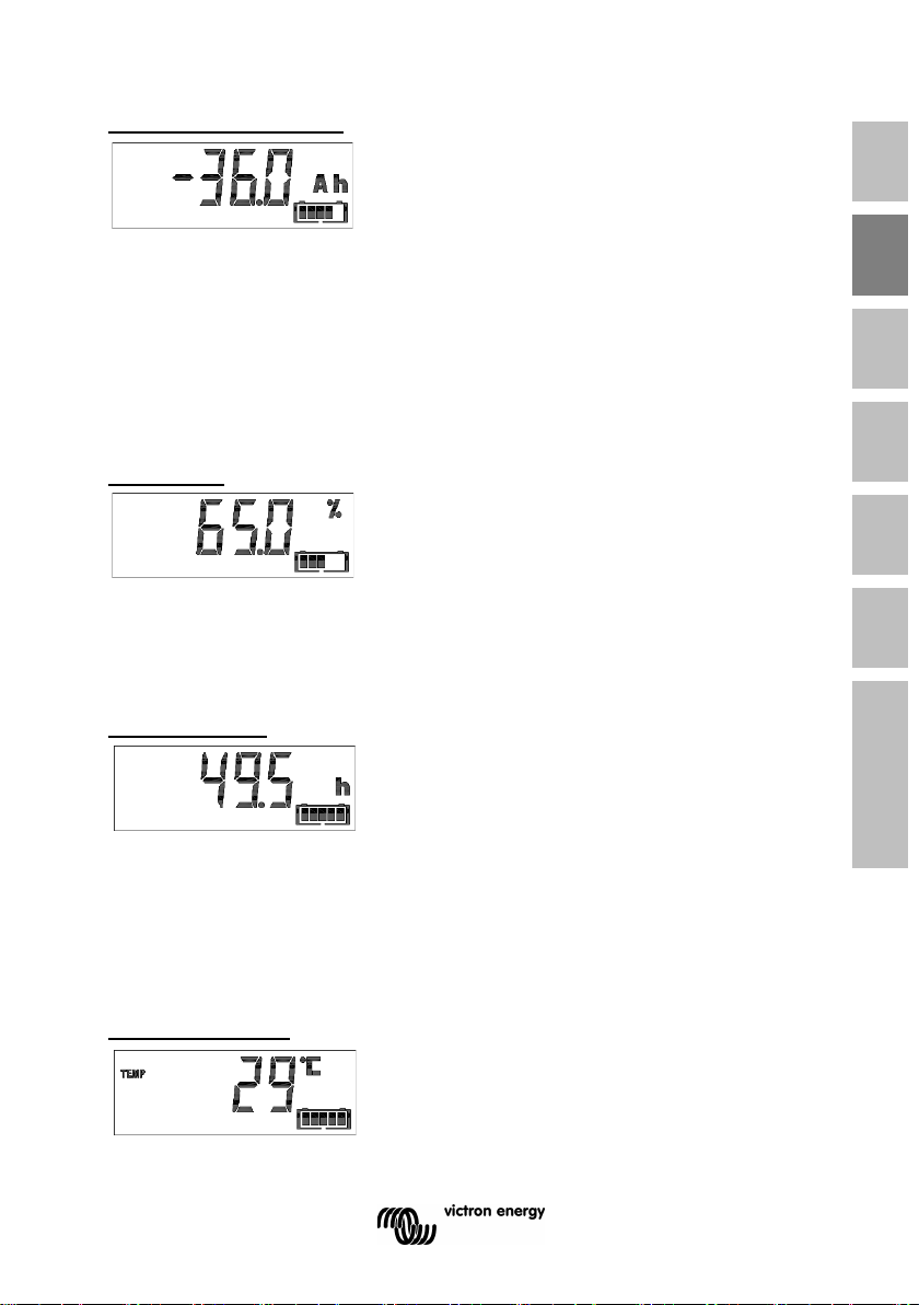
Verbruikte ampère-uur
De hoeveelheid door de accu verbruikte Ah
Voorbeeld:
Als gedurende 3 uur een stroom van 12 A van een volledig opgeladen
accu wordt ontladen, wordt er - 36,0 Ah weergegeven.
(-12 x 3 = -36)
Opmerking:
Drie streepjes ‘---’ zullen worden weergegeven wanneer de BMV is
gestart in niet-gesynchroniseerde status. Zie paragraaf 4.2.1, instelling
70.
Laadstatus
Bij een volledig opgeladen accu wordt de
waarde 100,0 % weergegeven. Bij een
volledig ontladen accu wordt de waarde 0,0
% weergegeven.
Opmerking:
Drie streepjes ‘---’ zullen worden weergegeven wanneer de BMV is
gestart in niet-gesynchroniseerde status. Zie paragraaf 4.2.1, instelling
70.
Resterende tijd
Dit is een schatting van de tijd die de accu de
huidige belasting nog in stand kan houden
voordat deze weer moet worden opgeladen.
De weergegeven resterende tijd is de tijd tot
volledige ontlading is bereikt.
Zie 4.2.2, instelling nr. 16.
Opmerking:
Drie streepjes ‘---’ zullen worden weergegeven wanneer de BMV is
gestart in niet-gesynchroniseerde status. Zie paragraaf 4.2.1, instelling
70.
Accutemperatuur
Alleen bij BMV-702 en -712, als de
hulpingang is ingesteld op TEMP
De waarde kan worden weergegeven in
graden Celsius of graden Fahrenheit.
Zie paragraaf 4.2.5.
9
EN NL FR DE ES SE Appendix
NL FR DE ES SE IT PT
Page 52
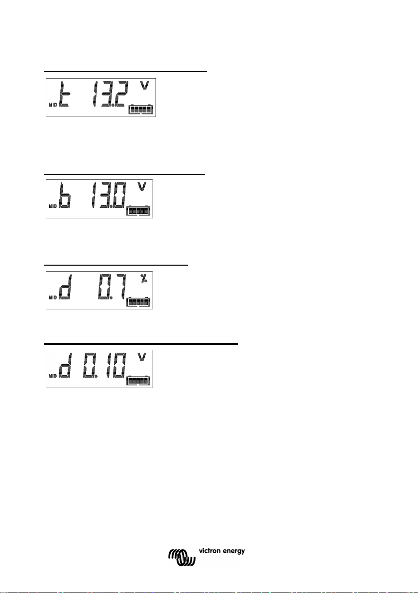
Spanning bovenste deel accubank
Alleen bij BMV-702 en -712, als de
hulpingang is ingesteld op MID.
Vergelijk deze waarde met de spanning van
het onderste deel om het evenwicht in de accu te controleren.
Zie voor meer informatie over bewaking van de middelpuntspanning van
de accu paragraaf 5.2.
Spanning onderste deel accubank
Alleen bij BMV-702 en -712, als de
hulpingang is ingesteld op MID.
Vergelijk deze waarde met de spanning van het bovenste deel om het
evenwicht in de accu te controleren.
Middelpuntafwijking accubank
Alleen bij BMV-702 en -712, als de
hulpingang is ingesteld op MID.
Dit is de afwijking in procenten van de gemeten middelpuntspanning.
Middelpuntspanningsafwijking accubank
Alleen bij BMV-702 en -712, als de
hulpingang is ingesteld op MID.
Dit is de afwijking in volt van de middelpuntspanning.
2.2 Synchronisatie van de BMV
Voor een betrouwbare waardeweergave moet de laadstatus die wordt
weergegeven door de accumonitor regelmatig worden gesynchroniseerd
met de werkelijke laadstatus van de accu. Dit wordt bereikt door de accu
volledig op te laden.
In het geval van een 12 V-accu wordt de BMV opnieuw ingesteld op
‘volledig opgeladen’ als wordt voldaan aan de volgende ‘laadparameters’:
de spanning overschrijdt 13,2 V en tegelijkertijd bedraagt de (staart-)
laadstroom gedurende 3 minuten minder dan 4,0 % van de totale
accucapaciteit (bv. 8 A voor een 200 Ah accu).
10
Page 53

De BMV kan indien nodig ook handmatig worden gesynchroniseerd
(d.w.z. op ‘accu volledig opgeladen’ worden gezet). Dit kan worden
bereikt in de normale bedrijfsmodus door de knoppen + en – tegelijkertijd
3 seconden lang ingedrukt te houden, of in de instelmodus door de optie
SYNC (zie paragraaf 4.2.1, instelling nr. 10).
Standaard is de BMV geconfigureerd om in een niet-gesynchroniseerde
status op te starten en wordt een laadstatus van 100 % aangeduid. Dit
gedrag kan worden gewijzigd: zie paragraaf 4.2.1, instelling 70.
Als de BMV niet automatisch wordt gesynchroniseerd, moeten de
laadspanning, de staartstroom en/of de oplaadtijd eventueel worden
aangepast. Als de voeding van de BMV is onderbroken, moet de
accumonitor opnieuw worden gesynchroniseerd om juist te kunnen
werken.
Na de eerste synchronisatie (automatisch of handmatig), zal de BMV het
aantal automatische synchronisaties bijhouden: zie sectie 4.3.
Itemgeschiedenis SYNCHRONISATIONS.
2.3 Vaak voorkomende problemen
Geen tekenen van leven op de display
De BMV is waarschijnlijk niet goed aangesloten. De UTP-kabel moet aan
beide uiteinden goed worden ingestoken, de shunt moet worden
aangesloten op de minpool van de accu en de positieve voedingskabel
moet met geïnstalleerde zekering worden aangesloten op de pluspool
van de accu.
De temperatuursensor (indien van toepassing) moet worden aangesloten
op de pluspool van de accu bank (één van de twee draden van de sensor
fungeert als voedingsdraad).
De laadstroom en ontlaadstroom zijn omgekeerd
De laadstroom moet worden weergegeven met een positieve waarde.
Bijvoorbeeld: 1,45 A.
De ontlaadstroom moet worden weergegeven met een negatieve waarde.
Bijvoorbeeld: -1,45 A.
Als de laadstroom en de ontlaadstroom omgekeerd zijn, moeten de
voedingskabels op de shunt worden omgewisseld: zie de beknopte
installatiehandleiding.
EN NL FR DE ES SE Appendix
NL FR DE ES SE IT PT
11
Page 54

De BMV wordt niet automatisch gesynchroniseerd
Een mogelijkheid is dat de accu nooit volledig wordt opgeladen.
De andere mogelijkheid is dat de instelling voor de laadspanning moet
worden verlaagd en/of de staartstroom moet worden verhoogd.
Zie paragraaf 4.2.1.
De BMV synchroniseert te vroeg
In zonnesystemen of andere toepassingen met schommelende
laadstromen kunnen de volgende maatregelen worden getroffen om de
kans te verkleinen dat de BMV voortijdig naar een laadstatus van 100 %
gaat resetten:
c) Verhoog de “geladen” spanning naar slechts iets onder de absorptielaadspanning
(bijvoorbeeld: 14,2 V in geval van een 14,4 V absorptielaadspanning).
d) Verhoog de “geladen” detectietijd en/of verlaag de staartstroom om een voortijdige reset
door passerende wolken te voorkomen.
Zie paragraaf 4.2.1. voor set-up-aanwijzingen.
De symbolen synchronisatie en accu knipperen
Dit betekent dat de accu niet synchroniseert. Laad de accu's op en de
BMV zou dan automatisch moeten synchroniseren. Als dat niet werkt,
controleer dan de synchronisatie-instellingen. Of als u weet dat de accu
volledig is opgeladen, maar u niet wilt wachten tot de BMV synchroniseert:
houd dan de knoppen omhoog en omlaag tegelijkertijd ingedrukt tot u een
pieptoon hoort.
Zie paragraaf 4.2.1.
12
Page 55

BMV-
BMV-
BMV-
-712
Uitgebreide bewaking van een
enkele accu
• • •
•
Bewaking van de
accutemperatuur
•
Bewaking van de
accubank
• • •
Automatische detectie van de
nominale systeemspanning
• • •
Geschikt voor
hoogspanningssystemen
•
• • •
3 EIGENSCHAPPEN EN FUNCTIONALITEIT
3.1 Eigenschappen van de vier BMV-modellen
De BMV is beschikbaar in 4 modellen, die elk voor verschillende set van
vereisten dienen:
EN NL FR DE ES SE Appendix
NL FR DE ES SE IT PT
1
2 Basisbewaking van een hulpaccu
3
4
middelpuntspanning van een
5 Gebruik van andere shunts
6
7
8 Meerdere interfaceopties
Opmerking 1:
De eigenschappen 2, 3 en 4 zijn onderling exclusief.
Opmerking 2:
De kabel met de geïntegreerde temperatuursensor dient apart te worden
besteld (artikelnr.: ASS000100000). Deze temperatuursensor is niet
uitwisselbaar met andere Victron-temperatuursensoren die worden
gebruikt bij Multi's of acculaders.
3.2 Waarom moet ik mijn accu in de gaten houden?
Accu’s worden in vele toepassingen gebruikt, meestal voor het opslaan
van energie om later te gebruiken. Maar hoe weet u nu hoeveel energie
er in uw accu is opgeslagen? Dat is niet te zien met het blote oog.
13
700
700H
•
Page 56

De levensduur van accu's hangt af van vele factoren. De levensduur van
de accu kan worden verkort door onderlading, overlading, te diepe
ontlading, een te grote laad- of ontlaadstroom en een te hoge
omgevingstemperatuur. Door de accu met een geavanceerde
accumonitor te bewaken, krijgt de gebruiker belangrijke informatie om,
indien nodig, maatregelen te treffen. Hierdoor wordt de levensduur van de
accu verlengd en betaald zich de investering van de BMV snel terug.
3.3 Hoe werkt de BMV?
De voornaamste functie van de BMV is het volgen en aangeven van de
laadstatus van een accu, in het bijzonder om een onverwachte volledige
ontlading te voorkomen.
De BMV meet voortdurend de inkomende en uitgaande stroom van de
accu. De integratie van deze stroom gedurende bepaalde tijd (dat, als de
stroom een vast aantal ampère is, neerkomt op de vermenigvuldiging van
de stroom en de tijd) resulteert in het erbij gekomen of verloren gegane
netto aantal Ah.
Bijvoorbeeld: een ontlaadstroom van 10 A gedurende 2 uur neemt 10 x 2
= 20 Ah af van de batterij.
Om het wat ingewikkelder te maken, hangt het werkelijke accuvermogen
af van de ontlaadsnelheid en, in mindere mate, van de temperatuur.
En om het nog ingewikkelder te maken: bij het laden van een accu moet
meer Ah in de accu worden ‘gepompt’ dan kan worden gebruikt bij de
volgende ontlading. Met andere woorden: de laadefficiëntie is minder dan
100 %.
3.3.1. Over het accuvermogen en de ontlaadsnelheid
Het vermogen van een accu wordt aangegeven in ampère-uur (Ah).
Bijvoorbeeld: een loodzuuraccu die een stroom van 5 A gedurende 20 uur
kan leveren, heeft een vermogen van C
20 = 100 Ah (5 x 20 = 100).
Als dezelfde accu van 100 Ah volledig wordt ontladen in twee uur, kan
deze slechts C
2 = 56 Ah geven (door de hogere ontlaadsnelheid).
De BMV houdt rekening met dit verschijnsel aan de hand van de formule
van Peukert: zie paragraaf 5.1.
14
Page 57

3.3.2 Over de laadefficiëntie (CEF)
De laadefficiëntie van een loodzuuraccu is bijna 100 % zolang er geen
gasvorming plaatsvindt. Gasvorming betekent dat een deel van de
laadstroom niet wordt omgezet in chemische energie die wordt
opgeslagen in de accuplaten, maar wordt gebruikt om water om te zetten
in zuurstof en waterstofgas (uiterst explosief!). De in de platen
opgeslagen ‘ampère-uren’ kunnen bij de volgende ontlading worden
gebruikt, terwijl de ‘ampère-uren’ die worden gebruikt om water om te
zetten, verloren gaan.
Gasvorming kan eenvoudig worden vastgesteld bij natte accu's. Houd er
rekening mee dat als de laadfase van een verzegelde (VRLA) gel- en
AGM-accu eindigt in ‘enkel zuurstof’, dit de laadefficiëntie ook vermindert.
Een laadefficiëntie van 95 % betekent dat er 10 Ah naar de accu moet
worden overgebracht om 9,5 Ah daadwerkelijk in de accu opgeslagen te
verkrijgen. De laadefficiëntie van een accu is afhankelijk van het type, de
leeftijd en het gebruik van de accu.
De BMV houdt rekening met dit verschijnsel via de laadefficiëntiefactor:
zie paragraaf 4.2.2, instelling nr. 06.
3.4 Meerdere weergaveopties voor de laadtoestand van de accu
De BMV kan zowel de verloren ampère-uren (waarde ‘consumed Amphours’, enkel gecompenseerd voor de laadefficiëntie) als ook de
daadwerkelijke laadstatus in procenten weergeven (waarde ‘state of
charge’, gecompenseerd voor de laadefficiëntie en Peukert-efficiëntie).
De laadstatus aflezen is de beste manier om de accu te bewaken.
De BMV schat tevens hoe lang de accu de huidige belasting kan
uithouden: de waarde ‘time-to-go’ (resterende tijd). Dit is de daadwerkelijk
resterende tijd tot de accu volledig is ontladen. Af fabriek is de
ontlaadbodem ingesteld op 50 % (zie 4.2.2, instelling nr. 16).
Als de accubelasting erg schommelt, vertrouwt dan niet te veel op deze
waarde, aangezien het een kortstondige uitlezing betreft en enkel als
richtlijn mag worden gebruikt. Wij adviseren altijd de laadstatus te
gebruiken voor een nauwkeurige accubewaking. De laadtoestand-indicator
van de accu (zie hoofdstuk 7 "Display") schalen tussen de geconfigureerde
ontladingsvloer en 100 % ladingstoestand en weerspiegelt de effectieve
ladingstoestand.
EN NL FR DE ES SE Appendix
NL FR DE ES SE IT PT
15
Page 58

Veronderstelde
spanning (V)
< 18
12
13,2
18 - 36
24
26,4
> 36
48
52,8
BMV-700H
Nominale standaardspanning: 144 V
Standaard: 158,4 V
3.5 Geschiedenis
De BMV slaat gebeurtenissen op die later gebruikt kunnen worden om
gebruikspatronen en de toestand van de accu te evalueren.
Kies het menu geschiedenis door in de normale bedrijfsmodus op ENTER
te drukken (zie paragraaf 4.3).
3.6. Gebruik van andere shunts
De BMV wordt geleverd met een 500 A/50 mV shunt. Voor de meeste
toepassingen is deze shunt geschikt; de BMV kan echter worden
geconfigureerd voor een groot aantal verschillende shunts. Shunts tot
9999 A en/of 75 mV kunnen worden gebruikt.
Als u een andere dan de met de BMV meegeleverde shunt gebruikt, ga
dan als volgt te werk:
1. Schroef de PCB los van de geleverde shunt.
2. Monteer de PCB op de nieuwe shunt en zorg ervoor dat er
voldoende elektrisch contact is tussen de PCB en de shunt.
3. Verbind de shunt en de BMV zoals weergegeven in de
beknopte installatiehandleiding.
4. Volg de setup wizard (paragraaf 1.1 en 1.2).
5. Als de setup wizard is voltooid, stel dan de juiste shuntstroom
en shuntspanning in volgens paragraaf 4.2.5, instelling nr.65 en
66.
6. Als de BMV geen nulstroom aangeeft, zelfs als er geen
belasting is en de accu niet wordt opgeladen: kalibreer dan de
nulstroom (zie paragraaf 4.2.1, instelling nr. 09).
3.7 Automatische detectie van de nominale systeemspanning
De BMV past zich direct na het voltooien van de setup wizard
automatisch aan aan de nominale spanning van de accubank.
De volgende tabel geeft aan hoe de nominale spanning wordt bepaald en
hoe de laadspanningsparameter (zie paragraaf 2.2) dienovereenkomstig
wordt aangepast.
Gemeten
spanning (V)
nominale
Geladen spanning
(V)
BMV-700 & -702
& -712
16
Page 59

In geval van een andere nominale spanning van de accubank
(bijvoorbeeld 32 V), moet de laadspanning handmatig worden ingesteld:
zie paragraaf 4.2.1, instelling 02.
Aanbevolen instellingen:
Nominale accuspanning Aanbevolen instelling voor
laadspanning
12 V 13,2 V
24 V 26,4 V
36 V 39,6 V
48 V 52,8 V
60 V 66 V
120 V 132 V
144 V 158,4 V
288 V 316,8 V
3.8 Alarm, zoemer en relais
Bij de meeste waardes van de BMV kan een alarm worden afgegeven als
de waarde een ingestelde drempel bereikt. Als het alarm actief wordt,
begint de zoemer te piepen, gaat de achtergrondverlichting knipperen en
verschijnt het alarm-symbool in het display samen met de huidige
waarde.
Het betreffende gedeelte knippert eveneens. AUX als een startalarm
optreedt. MAIN, MID of TEMP voor het betreffende alarm.
(Als u zich in het menu setup bevindt en er een alarm optreedt, zal de
waarde die het alarm veroorzaakt niet zichtbaar zijn.)
Een alarm wordt bevestigd door op een willekeurige knop te drukken. Het
alarmsymbool wordt echter zolang weergegeven als de alarmsituatie blijft
bestaan.
Het is ook mogelijk om het relais te activeren als zich een alarmsituatie
voordoet.
BMV-700 en -702
Het relaiscontact is open als de spanning van de spoel wordt gehaald
(GEEN contact) en sluit zich als er weer spanning op het relais wordt
gezet.
Standaard fabrieksinstelling: het relais wordt gestuurd door de laadstatus
van de accubank. Het relais wordt weer onder spanning gezet als de
laadstatus naar minder dan 50 % (de 'ontlaadbodem') daalt en de
EN NL FR DE ES SE Appendix
NL FR DE ES SE IT PT
17
Page 60

spanning wordt er weer af gehaald als de accu weer is opgeladen tot 90
%. Zie paragraaf 4.2.2.
De relaisfunctie kan worden omgedraaid: spanning weghalen wordt dan
onder spanning zetten en omgekeerd. Zie paragraaf 4.2.2.
Als het relais onder spanning wordt gezet, stijgt de door de BMV
verbruikte stroom iets: zie technische gegevens.
BMV 712 Smart
De BMV 712 is ontworpen om het stroomverbruik tot een minimum te
beperken.
Het alarmrelais is daarom een bistabiel relais en het stroomverbruik blijft
laag ongeacht de positie of het relais.
3.9 Interface opties
3.9.1 Pc-software
Verbind de BMV met de pc via de “VE.Direct naar USB”-interfacekabel
(ASS030530010) en download de bijbehorende software.
VictronConnect-handleiding
3.9.2 Groot display en bewaking op afstand
De Color Control GX, met een 4,3" kleurendisplay, biedt intuïtieve
besturing en bewaking voor alle aangesloten producten. De lijst met
Victron-producten die aangesloten kunnen worden, is eindeloos:
omvormers, Multi's, Quattro's, MPPT-zonneladers, BMV, Skylla-i, Lynx
Ion en nog veel meer. De BMV kan via een VE.Direct kabel worden
verbonden met de Color Control GX. Het is tevens mogelijk om deze via
de VE.Direct to USB interface te verbinden. Naast lokale besturing en
bewaking met de Color Control GX wordt de informatie tevens
doorgestuurd naar onze gratis website voor bewaking op afstand: het
VRM Online Portal. Zie voor meer informatie de documentatie van de
Color Control GX op onze website.
3.9.3 Aangepaste integratie (programmering vereist)
De VE.Direct communicatiepoort kan worden gebruikt om data te lezen
en instellingen te wijzigen. Het VE.Direct protocol kan heel eenvoudig
worden geïmplementeerd. De overdracht van gegevens naar de BMV is
voor eenvoudige toepassingen niet nodig: de BMV stuurt elke seconde
automatisch alle waarden door. Alle details worden uitgelegd in het
document:
Data communication with Victron Energy products
18
Page 61

3.10 Extra functionaliteiten van de BMV-702 en -712
Naast de uitgebreide bewaking van het hoofdaccusysteem, biedt de
BMV-702 en -712 een tweede bewakingsingang. Wanneer ingeschakeld,
heeft deze secundaire ingang drie configureerbare opties, hier beneden
beschreven.
3.10.1 Bewaking van de hulpaccu
Zie voor het bedradingsschema de beknopte installatiehandleiding. Afb. 3
De configuratie biedt een primaire bewaking van een tweede accu door
weergave van de spanning van deze accu. Dit is handig voor systemen
met een afzonderlijke startaccu.
3.10.2 Bewaking van de accutemperatuur
Zie voor het bedradingsschema de beknopte installatiehandleiding. Afb. 4
De kabel met de geïntegreerde temperatuursensor dient apart te worden
besteld (artikelnr.: ASS000100000). Deze temperatuursensor is niet
uitwisselbaar met andere Victron-temperatuursensoren die bijvoorbeeld
met de Multi's of acculaders worden meegeleverd. De temperatuursensor
moet worden aangesloten op de pluspool van de accubank (één van de
twee draden van de sensor fungeert als de voedingsdraad).
De temperatuur kan worden weergegeven in graden Celsius of graden
Fahrenheit, zie paragraaf 4.2.5, instelling nr. 67.
De temperatuurmeting kan ook worden gebruikt om de accucapaciteit
aan de temperatuur aan te passen, zie paragraaf 4.2.5, instelling nr. 68.
De beschikbare accucapaciteit neemt af naarmate de temperatuur daalt.
De afname in vergelijking met de capaciteit bij 20 °C is 18 % bij 0 °C en
40 % bij -20 °C.
3.10.3 Bewaking van de middelpuntspanning
Zie voor het bedradingsschema de beknopte installatiehandleiding. Afb. 5
- 12
Door één slechte cel of één slechte accu kan een grote, dure accubank
defect raken.
Een kortsluiting of hoge interne lekstroom in één cel bijvoorbeeld kan
leiden tot onderlading van die cel en overlading van de overige cellen.
Evenzo kan door één slechte accu in een 24 V- of 48 V-bank van
meerdere in serie of parallel aangesloten 12 V-accu's de hele bank defect
raken.
Daarnaast moeten cellen of accu's die in serie zijn aangesloten allemaal
dezelfde beginlaadtoestand hebben. Kleine verschillen worden tijdens de
absorptie- of egalisatielading gecompenseerd, maar grote verschillen
EN NL FR DE ES SE Appendix
NL FR DE ES SE IT PT
19
Page 62

leiden tot beschadiging tijdens het opladen als gevolg van overmatige
gasvorming in de cellen of accu's met de hoogste beginlaadtoestand.
Een tijdig alarm kan worden afgegeven door bewaking van het
middelpunt van de accubank. Zie voor meer informatie paragraaf 5.1.
3.11 Aanvullende functionaliteit van de BMV-712 Smart
3.11.1 Automatisch bladeren door status-items
De BMV-712 kan worden geïnstrueerd om de status-items automatisch te
doorlopen door de min-knop gedurende 3 seconden ingedrukt te houden.
Hierdoor kan men de status van zijn systeem in de controleren zonder de
BMV-712 te hoeven bedienen. Het automatisch bladeren door
statusitems wordt uitgeschakeld door de min knop 3 seconden ingedrukt
te houden of door de setup knop 2 seconden ingedrukt te houden (dit zal
de setup-modus inschakelen).
3.11.2 Bluetooth In-/Uitschakelen
De geïntegreerde Bluetooth-module van de BMV-712 kan via het
instellingenmenu worden in- of uitgeschakeld. Zie paragraaf 4.2.1,
instelling 71.
20
Page 63

Functie
In de normale modus
In de setup-modus
Als de achtergrondverlichting uit is, druk dan op een willekeurige knop om de
achtergrondverlichting in te schakelen
Druk op elk gewenst moment op SETUP om
weergegeven.
- Druk op deze knop om het scrollen te
om weer een instelling te doen.
Houd de knoppen SETUP en
paragraaf 4.2.5)
Als u geen wijzigingen doorvoert, drukt u op
parameter te gaan.
Als wijzigingen doorvoert, verhoogt u met
cijfer.
Als u geen wijzigingen doorvoert, drukt u op
parameter te gaan.
Als wijzigingen doorvoert, verlaagt u met
cijfer.
Houd beide knoppen gelijktijdig
synchroniseren.
4 INSTELLINGEN
4.1 Gebruik van de menu's
(gebruik anders de VictronConnect app en een smartphone)
De BMV wordt met vier knoppen bestuurd. De functie van de knoppen
hangt af van de modus, waarin de BMV zich bevindt.
Knop
EN NL FR DE ES SE Appendix
NL FR DE ES SE IT PT
Twee seconden lang ingedrukt
houden om naar de setupmodus
te wisselen.
SETUP
SELECT
SETUP/
SELECT
+ Omhoog gaan
–
Het display geeft scrollend het
nummer en de beschrijving van
de geselecteerde parameter
weer.
Druk op deze knop om naar het
menu geschiedenis te wisselen.
Druk op deze knop om het
scrollen te stoppen en de waarde
te laten weergeven. Druk
nogmaals op deze knop om terug
te keren naar de normale modus.
SELECT tegelijkertijd drie
seconden lang ingedrukt om de
fabrieksinstellingen te herstellen
(uitgeschakeld als instelling 64,
vergrendelingssetup, aan is, zie
Omlaag gaan
Alleen BMV-712: Houd drie
seconden ingedrukt (tot de
bevestigingstoon) om het
automatisch door statusitems
bladeren te starten of te stoppen.
terug te keren naar de scrollende tekst en
druk nogmaals op deze knop om terug te
keren naar de normale modus.
Als u op de knop SETUP drukt terwijl een
parameter zich buiten het bereik bevindt,
dan knippert het display 5 keer en wordt de
dichtstbijzijnde geldige waarde
stoppen als u zich door op de knop SETUP
te drukken in de setupmodus bevindt.
- Na het instellen van het laatste cijfer drukt
u op deze knop om het instellen af te sluiten.
De waarde wordt automatisch opgeslagen.
Dit wordt bevestigd door een korte pieptoon.
- Druk, indien nodig, nogmaals op deze knop
deze knop om omhoog naar de vorige
deze knop de waarde van het geselecteerde
deze knop om omlaag naar de volgende
deze knop de waarde van het geselecteerde
+/–
drie seconden lang ingedrukt om
de BMV handmatig te
21
Page 64

Als de BMV de eerste keer in bedrijf wordt gesteld of als de
fabrieksinstellingen zijn hersteld, start de BMV de snelle setup-wizard: zie
hoofdstuk 1.
Daarna start de BMV als deze wordt ingeschakeld in de normale modus:
zie hoofdstuk 2.
4.2 Functieoverzicht
Het volgende overzicht beschrijft alle parameters van de BMV.
- Druk twee seconden lang op de knop SETUP om toegang tot deze
functies te krijgen en gebruik de knoppen + en – om door de functies
te bladeren.
- Druk op de knop SELECT om toegang tot de gewenste parameter te
krijgen.
- Gebruik de knoppen SELECT en + en – om de parameter in te stellen.
Een korte pieptoon bevestigt de instelling.
- Druk op elk gewenst moment op SETUP om terug te keren naar de
scrollende tekst en druk nogmaals op deze knop om terug te keren
naar de normale modus.
4.2.1 Accu-instellingen
______________________________________________________________
01. Battery capacity
De accucapaciteit in ampère-uur
Standaard Bereik Stapgrootte
200 Ah 1 – 9999 Ah 1 Ah
______________________________________________________________
02. Charged Voltage
De geladen spanning. De accu wordt als volledig geladen beschouwd als de
accuspanning hoger is dan deze spanningswaarde.
De parameter 'Geladen spanning' dient altijd iets onder de eindlaadspanning van de acculader te
liggen (meestal 0,2 V of 0,3 V onder de 'druppelladings'-spanning van de acculader).
Zie paragraaf 3.7 voor de aanbevolen instellingen.
BMV-700 / BMV-702
Standaard Bereik Stapgrootte
Zie tabel, par. 3,7 0 – 95 V 0,1 V
BMV-712 Smart
Standaard Bereik Stapgrootte
Zie tabel, par. 3,7 0 – 70 V 0,1 V
BMV-700H
Standaard Bereik Stapgrootte
158,4 V 0 – 384 V 0,1 V
22
Page 65

______________________________________________________________
03. Tail current
De staartstroom. Zodra de laadstroom onder de ingestelde staartstroom is gedaald
(uitgedrukt als een percentage van de accucapaciteit), wordt de accu beschouwd als
volledig opgeladen.
Opmerking:
Sommige acculaders stoppen met opladen als de stroom onder de ingestelde drempelwaarde daalt. De
staartstroom moet hoger worden ingesteld dan deze drempelwaarde.
Standaard Bereik Stapgrootte
4 % 0,5 – 10 % 0,1 %
______________________________________________________________
04. Charged detection time
De detectietijd opgeladen. Dit is de tijd, waarin aan de parameters (Charged Voltage en
Tail Current) moet worden voldaan om de accu als volledig opgeladen te kunnen
beschouwen.
Standaard Bereik Stapgrootte
3 minuten 1 – 50 minuten 1 minuut
______________________________________________________________
05. Peukert exponent
De Peukert-exponent. Indien onbekend, wordt aanbevolen om deze waarde op 1.25
(standaard) te houden voor loodzwavelzuuraccu's en te wijzigen naar 1.05 voor lithiumionaccu's. Een waarde van 1.00 schakelt de Peukert-compensatie uit.
Standaard Bereik Stapgrootte
1,25 1 – 1,5 0,01
______________________________________________________________
06. Charge Efficiency Factor
De laadefficiëntiefactor. De laadefficiëntiefactor compenseert de verloren Ah tijdens het
laden.
100 % betekent geen verlies.
Standaard Bereik Stapgrootte
95 % 50 – 100 % 1 %
______________________________________________________________
07. Current threshold
De stroomdrempelwaarde. Als de gemeten stroom onder deze waarde daalt, wordt deze als
nul beschouwd.
De stroomdrempelwaarde wordt gebruikt om zeer lage stroomwaarden te compenseren die op de lange
termijn de uitlezing van de laadstatus negatief kunnen beïnvloeden in omgevingen met veel stoorsignalen.
Als bijvoorbeeld de daadwerkelijke lange-termijn-stroom 0.0 A bedraagt en als gevolg van stoorsignalen of
kleine compensaties de accumonitor 0.05 A meet, dan is de BMV op de lange termijn niet in staat om op
het juiste moment aan te geven dat de accu moet worden opgeladen. Als de stroomdrempelwaard in dit
voorbeeld wordt ingesteld op 0.1 A rekent de BMV met 0.0 A, zodat fouten worden uitgesloten.
Een waarde van 0.0 A schakelt deze functie uit.
Standaard Bereik Stapgrootte
0,1 A 0 – 2 A 0,01 A
EN NL FR DE ES SE Appendix
NL FR DE ES SE IT PT
23
Page 66

______________________________________________________________
08. Time-to-go averaging period
De gemiddelde resterende tijd. Deze geeft het tijdsinterval (in minuten) weer, waarmee het
voortschrijdend gemiddeldefilter werkt.
Een waarde van 0 schakelt het filter uit en geeft direct een (real-time) waarde weer; de weergegeven
waarde kan echter behoorlijk schommelen. Door de hoogste tijdswaarde (12 minuten) te selecteren,
waarborgt u dat bij het berekenen van de resterende tijd enkel rekening wordt gehouden met
belastingschommelingen op de lange termijn.
Standaard Bereik Stapgrootte
3 minuten 0 – 12 minuten 1 minuut
______________________________________________________________
09. Zero current calibration
De nulstroomkalibratie. Als de BMV een andere stroom dan nulstroom weergeeft, zelfs als er
geen belasting is en de accu niet wordt geladen, kan deze optie worden gebruikt om de
nulwaarde te kalibreren.
Zorg ervoor dat er echt geen stroom de accu in of uit gaat (koppel de kabel tussen de
belasting en de shunt los), druk daarna op SELECT.
______________________________________________________________
10. Synchronise
Synchroniseren: Deze optie kan worden gebruikt om de BMV handmatig te synchroniseren.
Druk op SELECT om te synchroniseren.
De BMV kan tevens worden gesynchroniseerd als deze zich in de normale bedrijfsmodus bevindt door de
knoppen + en – tegelijkertijd 3 seconden lang ingedrukt te houden.
______________________________________________________________
4.2.2 Relaisinstellingen
Opmerking: De drempelwaarden zijn uitgeschakeld als deze op 0 worden
ingesteld.
______________________________________________________________
11. Relay mode (relaismodus)
DFLT Standaardmodus van het relais. De relaisdrempelwaarden nr. 16 tot 31 kunnen worden
gebruikt om het relais te besturen.
CHRG Oplaadmodus van het relais. Het relais sluit zich als de laadstatus onder instelling 16
(ontlaadbodem) daalt of als de accuspanning onder instelling 18 (lage spanning relais) daalt.
Het relais gaat open als de laadstatus hoger is dan instelling 17 (laadstatus relais wissen) en
de accuspanning hoger is dan instelling 19 (lage spanning relais wissen).
Toepassingsvoorbeeld: start en stop de besturing van een generator, samen met instelling 14 en 15.
REM Afstandsmodus. De relais kan geregeld worden via de VE.Direct interface. Relais
instellingen 12 en 14 tot 31 worden genegeerd daar de relais volledig geregeld wordt door
het toestel verbonden via de VE.Direct interface.
______________________________________________________________
12. Invert relay
Het relais omkeren. Deze functie maakt het mogelijk om te wisselen tussen een normaal
niet onder spanning staand (open contact) of een normaal onder spanning staand (gesloten
contact) relais. Als het relais is omgekeerd worden de open en gesloten toestand zoals
beschreven in instelling 11 (DFLT en CHRG), en instelling 14 tot 31 omgekeerd.
De normaal onder spanning staande instelling zal de voedingsstroom in de normale bedrijfsmodus iets
verhogen.
Standaard Bereik
OFF: Niet onder spanning OFF: Niet onder spanning / ON: onder spanning
24
Page 67

______________________________________________________________
13. Relay state (alleen lezen)
De relaisstatus. Deze geeft aan of het relais open of gesloten (CLSD) is (niet onder spanning
of onder spanning staat).
Bereik
OPEN/CLSD
______________________________________________________________
14. Relay minimum closed time
De minimale sluitingstijd van het relais. Deze geeft de minimale hoeveelheid tijd aan die de
toestand CLOSED aanhoudt nadat het relais onder spanning is gezet.
niet onder spanning als de relaisfunctie is omgekeerd)
Toepassingsvoorbeeld: stel een minimale generatorlooptijd in (relais in CHRG-modus).
______________________________________________________________
15. Relay-off delay
De vertraging voor het uitschakelen van het relais. Deze geeft de hoeveelheid tijd aan die de
toestand 'relais spanningsloos' moet hebben aangestaan voordat het relais open gaat.
Toepassingsvoorbeeld: laat een generator een tijdje lopen om de accu beter op te laden (relais in CHRGmodus).
Standaard Bereik Stapgrootte
0 minuten 0 – 500 minuten 1 minuut
______________________________________________________________
16. SoC relay
Laadstatus van het relais (ontlaadbodem). Als het percentage van de laadstatus onder deze
waarde is gedaald, wordt het relais gesloten.
De weergegeven resterende tijd is de tijd tot volledige ontlading (ontlaadbodem) is bereikt.
Standaard Bereik Stapgrootte
50 % 0 – 99 % 1 %
(Discharge floor)
______________________________________________________________
17. Clear SoC relay
Laadstatus van het relais wissen. Als het percentage van de laadstatus boven deze waarde
komt, gaat het relais open (na een vertraging, afhankelijk van instelling 14 en/of 15). Deze
waarde moet groter zijn dan de vorige parameterinstelling. Als de waarde gelijk is aan de
vorige parameter zal het percentage van de laadstatus er niet voor zorgen dat het relais
wordt gesloten.
Standaard Bereik Stapgrootte
90 % 0 – 99 % 1 %
______________________________________________________________
18. Low voltage relay
Lage spanning relais. Als de accuspanning meer dan 10 seconden onder deze waarde daalt,
dan wordt het relais gesloten.
______________________________________________________________
19. Clear low voltage relay
Lage spanning relais wissen. Als de accuspanning boven deze waarde komt, gaat het relais
open (na een vertraging, afhankelijk van instelling 14 en/of 15). Deze waarde moet hoger zijn
dan of gelijk zijn aan de vorige parameter.
______________________________________________________________
20. High voltage relay
Hoge spanning relais. Als de accuspanning meer dan 10 seconden boven deze waarde blijft,
wordt het relais gesloten.
(wisselt naar OPEN en
EN NL FR DE ES SE Appendix
NL FR DE ES SE IT PT
25
Page 68

______________________________________________________________
21. Clear high voltage relay
Hoge spanning relais wissen. Als de accuspanning onder deze waarde daalt, gaat het relais
open (na een vertraging, afhankelijk van instelling 14 en/of 15). Deze waarde moet lager zijn
dan of gelijk zijn aan de vorige parameter.
BMV-700 / BMV-702 / BMV 712 Smart
Standaard Bereik Stapgrootte
0 V 0 – 95 V 0,1 V
BMV-700H
Standaard Bereik Stapgrootte
0 V 0 – 384 V 0,1 V
______________________________________________________________
22. Low starter voltage relay - alleen bij 702 en -712
Lage startspanning relais. Als de hulpspanning (bv. startaccu) meer dan 10 seconden onder
deze waarde daalt, wordt het relais geactiveerd.
______________________________________________________________
23. Clear low starter voltage relay - alleen bij 702 en -712
Lage startspanning relais wissen. Als de hulpspanning boven deze waarde komt, gaat het
relais open (na een vertraging, afhankelijk van instelling 14 en/of 15). Deze waarde moet
hoger zijn dan of gelijk zijn aan de vorige parameter.
______________________________________________________________
24. High starter voltage relay - alleen bij 702 en -712
Hoge startspanning relais. Als de hulpspanning (bv. startaccu) meer dan 10 seconden
boven deze waarde blijft, wordt het relais geactiveerd.
______________________________________________________________
25. Clear high starter voltage relay - alleen bij 702 en -712
Hoge startspanning relais wissen. Als de hulpspanning onder deze waarde daalt, gaat het
relais open (na een vertraging, afhankelijk van instelling 14 en/of 15). Deze waarde moet
lager zijn dan of gelijk zijn aan de vorige parameter.
Standaard Bereik Stapgrootte
0 V 0 – 95 V 0,1 V
______________________________________________________________
26. High temperature relay - alleen bij 702 en -712
Hoge temperatuur relais. Als de accutemperatuur meer dan 10 seconden boven deze waarde
blijft, wordt het relais geactiveerd.
______________________________________________________________
27. Clear high temperature relay - alleen bij 702 en -712
Hoge temperatuur relais wissen. Als de temperatuur onder deze waarde daalt, gaat het relais
open (na een vertraging, afhankelijk van instelling 14 en/of 15). Deze waarde moet lager zijn
dan of gelijk zijn aan de vorige parameter.
______________________________________________________________
28. Low temperature relay - alleen bij 702 en -712
Lage temperatuur relais. Als de temperatuur meer dan 10 seconden onder deze waarde blijft,
wordt het relais geactiveerd.
26
Page 69

______________________________________________________________
29. Clear low temperature relay - alleen bij 702 en -712
Lage temperatuur relais wissen. Als de temperatuur boven deze waarde komt, gaat het relais
open (na een vertraging, afhankelijk van instelling 14 en/of 15). Deze waarde moet hoger zijn
dan of gelijk zijn aan de vorige parameter.
Zie instelling 67 om te kiezen tussen °C en °F.
Standaard Bereik Stapgrootte
0 °C -40 – 99 °C 1 °C
0 °F -40 – 210 °F 1 °F
______________________________________________________________
30. Mid voltage relay - alleen bij 702 en -712
Middelpuntspanning relais. Als de afwijking van de middelpuntspanning meer dan 10
seconden boven deze waarde blijft, wordt het relais geactiveerd. Zie paragraaf 5.2 voor meer
informatie over de middelpuntspanning.
______________________________________________________________
31. Clear mid voltage relay - alleen bij 702 en -712
Middelpuntspanning relais wissen. Als de afwijking van de middelpuntspanning onder deze
waarde daalt, gaat het relais open (na een vertraging, afhankelijk van instelling 14 en /of 15).
Deze waarde moet lager zijn dan of gelijk zijn aan de vorige parameter.
Standaard Bereik Stapgrootte
0 % 0 – 99 % 0,1 %
______________________________________________________________
4.2.3 Alarmzoemerinstellingen
Opmerking: De drempelwaarden zijn uitgeschakeld als deze op 0 worden
ingesteld.
______________________________________________________________
32. Alarm buzzer (alarmzoemer)
Als deze is ingeschakeld, geeft de zoemer een alarmsignaal af. Het geluid kan worden
stopgezet door op een willekeurige knop te drukken. Indien uitgeschakeld, klinkt de zoemer
niet in geval van alarm.
Standaard Bereik
ON ON/OFF
______________________________________________________________
33. Low SoC alarm (alarm lage laadstatus)
Als de laadstatus meer dan 10 seconden onder deze waarde blijft, wordt het alarm 'Lage
laadstatus' geactiveerd. Dit is een zichtbaar en hoorbaar alarm. Hierdoor wordt het relais niet
onder spanning gezet.
______________________________________________________________
34. Clear low SoC alarm (alarm lage laadstatus stoppen)
Als de laadstatus boven deze waarde komt, wordt het alarm uitgeschakeld. Deze waarde
moet hoger zijn dan of gelijk zijn aan de vorige parameter.
Standaard Bereik Stapgrootte
0 % 0 – 99 % 1 %
EN NL FR DE ES SE Appendix
NL FR DE ES SE IT PT
27
Page 70

______________________________________________________________
35. Low voltage alarm (alarm lage spanning)
Als de accuspanning meer dan 10 seconden onder deze waarde blijft, wordt het alarm
'Spanning laag' geactiveerd. Dit is een zichtbaar en hoorbaar alarm. Hierdoor wordt het relais
niet onder spanning gezet.
______________________________________________________________
36. Clear low voltage alarm (alarm lage spanning stoppen)
Als de accuspanning boven deze waarde komt, wordt het alarm uitgeschakeld. Deze waarde
moet hoger zijn dan of gelijk zijn aan de vorige parameter.
______________________________________________________________
37. High voltage alarm (alarm hoge spanning)
Als de accuspanning meer dan 10 seconden boven deze waarde blijft, wordt het alarm 'Hoge
spanning' geactiveerd. Dit is een zichtbaar en hoorbaar alarm. Hierdoor wordt het relais niet
onder spanning gezet.
______________________________________________________________
38. Clear high voltage alarm (alarm hoge spanning stoppen)
Als de accuspanning onder deze waarde komt, wordt het alarm uitgeschakeld. Deze waarde
moet lager zijn dan of gelijk zijn aan de vorige parameter.
BMV-700 / BMV-702 / BMV-712 Smart
Standaard Bereik Stapgrootte
0 V 0 – 95 V 0,1 V
BMV-700H
Standaard Bereik Stapgrootte
0 V 0 – 384 V 0,1 V
______________________________________________________________
39. Low starter voltage alarm (alarm lage startspanning) –
alleen bij 702 en -712
Als de hulpspanning (bv. startaccu) meer dan 10 seconden onder deze waarde blijft, wordt
het alarm geactiveerd. Dit is een zichtbaar en hoorbaar alarm. Hierdoor wordt het relais niet
onder spanning gezet.
______________________________________________________________
40. Clear low starter voltage alarm (alarm lage startspanning stoppen) - alleen
bij 702 en -712
Als de hulpspanning boven deze waarde komt, wordt het alarm uitgeschakeld. Deze waarde
moet hoger zijn dan of gelijk zijn aan de vorige parameter.
______________________________________________________________
41. High starter voltage alarm (alarm hoge startspanning) –
alleen bij 702 en -712
Als de hulpspanning (bv. startaccu) meer dan 10 seconden boven deze waarde blijft, wordt
het alarm geactiveerd. Dit is een zichtbaar en hoorbaar alarm. Hierdoor wordt het relais niet
onder spanning gezet.
______________________________________________________________
42. Clear high starter voltage alarm (alarm hoge startspanning stoppen) -
alleen bij 702 en -712
Als de hulpspanning onder deze waarde komt, wordt het alarm uitgeschakeld. Deze waarde
moet lager zijn dan of gelijk zijn aan de vorige parameter.
Standaard Bereik Stapgrootte
0 V 0 – 95 V 0,1 V
28
Page 71

______________________________________________________________
43. High temperature alarm (alarm hoge temperatuur) - alleen bij 702 en -712
Als de accutemperatuur meer dan 10 seconden boven deze waarde blijft, wordt het alarm
geactiveerd. Dit is een zichtbaar en hoorbaar alarm. Hierdoor wordt het relais niet onder
spanning gezet.
______________________________________________________________
44. Clear high temperature alarm (alarm hoge temperatuur stoppen) - alleen
bij 702 en -712
Als de temperatuur onder deze waarde komt, wordt het alarm uitgeschakeld. Deze waarde
moet lager zijn dan of gelijk zijn aan de vorige parameter.
______________________________________________________________
45. Low temperature alarm (alarm lage temperatuur) - alleen bij 702 en -712
Als de temperatuur meer dan 10 seconden onder deze waarde blijft, wordt het alarm
geactiveerd. Dit is een zichtbaar en hoorbaar alarm. Hierdoor wordt het relais niet onder
spanning gezet.
______________________________________________________________
46. Clear low temperature alarm (alarm lage temperatuur stoppen) - alleen bij
702 en -712
Als de temperatuur boven deze waarde komt, wordt het alarm uitgeschakeld. Deze waarde
moet hoger zijn dan of gelijk zijn aan de vorige parameter.
Zie parameter 67 om te kiezen tussen °C en °F.
Standaard Bereik Stapgrootte
0 °C -40 – 99 °C 1 °C
0 °F -40 – 210 °F 1 °F
______________________________________________________________
47. Mid voltage alarm (alarm middelpuntspanning) - alleen bij 702 en -712
Als de afwijking van de middelpuntspanning meer dan 10 seconden boven deze waarde blijft,
wordt het alarm geactiveerd. Dit is een zichtbaar en hoorbaar alarm. Hierdoor wordt het relais
niet onder spanning gezet.
Zie paragraaf 5.2 voor meer informatie over de middelpuntspanning.
Standaard Bereik Stapgrootte
2 % 0 – 99 % 0,1 %
______________________________________________________________
48. Clear mid voltage alarm (alarm middelpuntspanning stoppen) - alleen bij
702 en -712
Als de afwijking van de middelpuntspanning onder deze waarde komt, wordt het alarm
uitgeschakeld. Deze waarde moet lager zijn dan of gelijk zijn aan de vorige parameter.
Standaard Bereik Stapgrootte
1,5 % 0 – 99 % 0,1 %
4.2.4 Display instellingen
______________________________________________________________
49. Backlight intensity (intensiteit achtergrondverlichting)
De intensiteit van de achtergrondverlichting met een bereik van 0 (altijd uit) tot 9 (maximale
intensiteit).
Standaard Bereik Stapgrootte
5 0 – 9 1
EN NL FR DE ES SE Appendix
NL FR DE ES SE IT PT
29
Page 72

______________________________________________________________
50. Backlight always on (achtergrondverlichting altijd aan)
Als deze functie is ingeschakeld, wordt de achtergrondverlichting niet automatisch
uitgeschakeld na 60 seconden inactiviteit.
Standaard Bereik
OFF OFF/ON
______________________________________________________________
51. Scroll speed (scroll-snelheid)
De scroll-snelheid van het display met een bereik van 1 (heel langzaam) tot 5 (heel snel).
Standaard Bereik Stapgrootte
2 1 – 5 1
______________________________________________________________
52. Main voltage display (weergave hoofdspanning)
Deze instelling moet op ON (ingeschakeld) staan, om de spanning van de hoofdaccu in het
bewakingsmenu te laten weergeven.
______________________________________________________________
53. Current display (weergave stroom)
Deze instelling moet op ON staan om de stroom in het bewakingsmenu te laten weergeven.
______________________________________________________________
54. Power display (weergave vermogen)
Deze instelling moet op ON staan om het vermogen in het bewakingsmenu te laten
weergeven.
______________________________________________________________
55. Consumed Ah display (weergave verbruikte Ah)
Deze instelling moet op ON staan om de verbruikte Ah in het bewakingsmenu te laten
weergeven.
______________________________________________________________
56. State of charge display (weergave laadstatus)
Deze instelling moet op ON staan om de laadstatus in het bewakingsmenu te laten
weergeven.
______________________________________________________________
57. Time-to-go display (weergave resterende tijd)
Deze instelling moet op ON staan om de resterende tijd in het bewakingsmenu weer te geven.
______________________________________________________________
58 Starter voltage display (weergave startspanning) - alleen bij 702 en -712
Deze instelling moet op ON staan om de hulpspanning in het bewakingsmenu te laten
weergeven.
______________________________________________________________
59. Temperature display (weergave temperatuur) - alleen bij 702 en -712
Deze instelling moet op AAN staan om de temperatuur in het bewakingsmenu te laten
weergeven.
______________________________________________________________
60. Mid-voltage display (weergave middelpuntspanning) –
alleen bij 702 en -712
Deze instelling moet op AAN staan om de middelpuntspanning in het bewakingsmenu te laten
weergeven.
Standaard Bereik
ON ON/OFF
30
Page 73

______________________________________________________________
4.2.5 Diversen
______________________________________________________________
61. Software version (alleen lezen)
De softwareversie van de BMV.
______________________________________________________________
62. Restore defaults (standaardinstellingen herstellen)
Reset alle instellingen naar de standaardfabrieksinstellingen door op SELECT te drukken.
In de normale bedrijfsmodus kunnen de fabrieksinstellingen worden hersteld door tegelijkertijd 3 seconden
lang op SETUP en SELECT te drukken (alleen als instelling 64, Lock setup, is uitgeschakeld).
______________________________________________________________
63. Clear history (geschiedenis wissen)
Wis de complete geschiedenis door op SELECT te drukken.
______________________________________________________________
64. Lock setup (instellingen vergrendelen)
Indien deze instelling op ON staat, zijn alle instellingen (behalve deze) vergrendeld en
kunnen niet worden gewijzigd.
Standaard Bereik
OFF OFF/ON
______________________________________________________________
65. Shunt current (shunt stroom)
Als u een andere shunt gebruikt dan de bij de BMV geleverde shunt, stel deze waarde dan in
op de nominale stroom van de shunt.
Standaard Bereik Stapgrootte
500 A 1 – 9999 A 1 A
______________________________________________________________
66. Shunt voltage (shuntspanning)
Als u een andere shunt gebruikt dan de bij de BMV geleverde shunt, stel deze waarde dan in
op de nominale spanning van de shunt.
Standaard Bereik Stapgrootte
50 mV 1 mV– 75 mV 1 mV
______________________________________________________________
67. Temperature unit (temperatuureenheid)
CELC geeft de temperatuur weer in °C.
FAHR geeft de temperatuur weer in °F.
Standaard Bereik
CELC CELC/FAHR
______________________________________________________________
68. Temperature coefficient (temperatuurcoëfficiënt)
Dit is het percentage, waarmee de accucapaciteit wijzigt samen met de temperatuur, als de
temperatuur daalt naar minder dan 20 °C (boven 20 °C is de invloed van de temperatuur op
de capaciteit relatief klein en kan buiten beschouwing worden gelaten). De eenheid van deze
waarde is ‘ %cap/°C’ of procent capaciteit per graden Celsius. De typische waarde (onder 20
°C) is 1 %cap/°C voor loodzwavelzuuraccu's, en 0,5 %cap/°C voor lithium-ijzerfosfaataccu's.
Standaard Bereik Stapgrootte
0 %cap/°C 0 – 2 %cap/°C 0,1 %cap/°C
EN NL FR DE ES SE Appendix
NL FR DE ES SE IT PT
31
Page 74

______________________________________________________________
69. Aux input (hulpingang)
Stelt de functie van de hulpingang in:
NONE
Schakelt de aux-ingang uit (standaard)
START Hulpspanning, bv. van een startaccu.
MID Middelpuntspanning.
TEMP Accu temperatuur.
De kabel met de geïntegreerde temperatuursensor dient apart te worden besteld (artikelnr.:
ASS000100000). Deze temperatuursensor is niet uitwisselbaar met andere Victrontemperatuursensoren die worden gebruikt bij Multi's of acculaders.
______________________________________________________________
70. Start gesynchroniseerd
Wanneer INGESCHAKELD, zal de BMV zichzelf als gesynchroniseerd beschouwen als
ingeschakeld, wat resulteert in een laadtoestand van 100 %
UITGESCHAKELD, zal de BMV het niet-gesynchroniseerd beschouwen wanneer het wordt
ingeschakeld, wat resulteert in een laadtoestand die onbekend is tot de eerste werkelijke
synchronisatie.
Standaard Bereik
ON OFF/ON
______________________________________________________________
71. Bluetooth modus (alleen BMV712)
Bepaalt of Bluetooth wordt ingeschakeld. Indien uitgeschakeld met behulp van de
VictronConnect app, wordt de Bluetooth-functie niet uitgeschakeld totdat losgekoppeld van de
BMV. Houd er rekening mee dat deze instelling alleen beschikbaar is als de firmware van de
ingebouwde Bluetooth-module deze functie ondersteunt.
Standaard Bereik
ON OFF/ON
Wanneer ingesteld op
32
Page 75

Parameter
Beschrijving
De diepste ontlading in Ah.
De hoogst geregistreerde waarde voor
synchronisatie.
Gemiddelde ontladingsdiepte
Het aantal oplaadcyclussen. Een
boven 90 % komt.
Het aantal volledige ontladingen. Er wordt
laadstatus 0 % bereikt.
De cumulatieve hoeveelheid Ampère-uren
ontladen aan de accu.
De laagste accuspanning.
De hoogste accuspanning.
Het aantal dagen sinds de laatste keer dat
de accu volledig is geladen.
Het aantal automatische synchronisaties.
geteld
Het aantal alarmen lage spanning.
Het aantal alarmen hoge spanning.
De laagste hulpaccuspanning.
De hoogste hulpaccuspanning.
De totale hoeveelheid aan de accu
onttrokken energie in (k)Wh
De totale hoeveelheid door de accu
opgenomen energie in (k)Wh
4.3 Geschiedenis
De BMV slaat een groot aantal parameters betreffende de status van de
accu op, die gebruikt kunnen worden om gebruikspatronen en de
toestand van de accu te evalueren.
Ga naar de geschiedenis door op de knop SELECT in de normale modus
te drukken.
Druk op + of – om door de verschillende parameters te bladeren.
Druk nogmaals op SELECT om het scrollen te stoppen en de waarde te
laten weergeven.
Druk op + of – om door de verschillende waarden te bladeren.
Druk nogmaals op SELECT om het menu geschiedenis te verlaten en
terug te keren naar de normale bedrijfsmodus.
De geschiedenis wordt opgeslagen in het niet-vluchtige geheugen en gaat
niet verloren als de stroomvoorziening naar de BMV wordt onderbroken.
verbruikte Ah sinds de laatste
oplaadcyclus wordt elke keer geteld als de
laadstatus onder 65 % daalt en vervolgens
EN NL FR DE ES SE Appendix
NL FR DE ES SE IT PT
* alleen bij BMV-702 en -712
een volledige ontlading geteld als de
Elke keer dat de laadstatus onder de 90 %
komt, voordat er een synchronisatie
plaatsvindt, wordt er een synchronisatie
33
Page 76

A
h
Ah
I
ht
AhC
h
15
5
75
5
75
1
1
5
==
=
=
21
12
loglog
loglog
IItt−
−
tnICp ⋅=
5 MEER OVER DE PEUKERT-EXPONENT EN
MIDDELPUNTBEWAKING
5.1 De Peukert-exponent: accucapaciteit en ontlaadsnelheid
De waarde die in de formule van Peukert kan worden aangepast is de
exponent n: zie de onderstaande formule.
De exponent van Peukert kan voor de BMV worden ingesteld van 1,00 tot
1,50. Hoe hoger de exponent van Peukert, des te sneller het effectieve
vermogen ‘afneemt’ en de ontlaadsnelheid toeneemt. Een ideale
(theoretische) accu heeft een Peukert-exponent van 1,00 en heeft een
vaste capaciteit; ongeacht de grootte van de ontlaadstroom. De
standaardinstelling voor de Peukert-exponent is 1,25. Dit is een
aanvaardbare gemiddelde waarde voor de meeste loodzwavelzuuraccu's.
De Peukert-vergelijking luidt als volgt:
waarbij de Peukert-exponent n =
De accuspecificaties die nodig zijn voor de berekening van de Peukertexponent zijn de nominale accucapaciteit (meestal de 20-uurs
ontlaadsnelheid
Onderstaand vindt u een voorbeeld voor het berekenen van de Peukertexponent aan de hand van deze twee specificaties.
5-uurs snelheid
1
) en bijvoorbeeld een 5-uurs ontlaadsnelheid2.
1
Opmerking: Het nominale accuvermogen kan ook een ontlaadsnelheid van 10 uur of zelfs
van 5 uur hebben.
2
Een ontlaadsnelheid van 5 uur in dit voorbeeld is slechts willekeurig. Zorg ervoor dat
behalve de nominale waarde C
een aanzienlijk hogere ontlaadstroom wordt gekozen.
34
20 (lage ontlaadstroom) een tweede nominale waarde met
Page 77

A
h
Ah
I
h
AhC
h
5
20
100
20t
vermogen)(nominaal 100
2
2
20
==
=
=
1.26
=
−
−
=
5log15log
5log20log
exponent,Peukert n
20-uurs snelheid
U vindt een Peukert-calculator op Downloads
Opmerking: De Peukert-formule is slechts een ruwe benadering van de
werkelijkheid en accu's leveren bij erg hoge stroom zelfs een lager
vermogen dan voorspeld op basis van een vaste exponent.
Aanbevolen wordt om de standaardwaarde in de BMV niet te wijzigen,
behalve in het geval van lithium-ionaccu's: Zie hoofdstuk 6.
5.2 Bewaking van de middelpuntspanning
Zie voor het bedradingsschema de beknopte installatiehandleiding. Afb.
5-12
Door één slechte cel of één slechte accu kan een grote, dure accubank
defect raken.
Een kortsluiting of hoge interne lekstroom in één cel bijvoorbeeld kan
leiden tot onderlading van die cel en overlading van de overige cellen.
Evenzo kan door één slechte accu in een 24 V- of 48 V-bank van
meerdere in serie of parallel aangesloten 12 V-accu's de hele bank defect
raken.
Daarnaast moeten, als nieuwe cellen of accu's in serie worden
aangesloten, allemaal dezelfde beginlaadtoestand hebben. Kleine
verschillen worden tijdens de absorptie- of egalisatielading
gecompenseerd, maar grote verschillen leiden tot beschadiging tijdens
het opladen als gevolg van overmatige gasvorming in de cellen of accu's
met de hoogste beginlaadtoestand.
35
EN NL FR DE ES SE Appendix
NL FR DE ES SE IT PT
Page 78

Een tijdig alarm kan worden afgegeven door bewaking van het
middelpunt van de accubank (d.w.z. door de seriespanning in tweeën te
delen en de twee seriespanningshelften met elkaar te vergelijken).
Opmerking: De middelpuntafwijking is klein als de accubank zich in de
ruststand bevindt en zal toenemen:
a) aan het einde van de bulkladingsfase tijdens het opladen (de
spanning van goed opgeladen cellen zal snel toenemen terwijl slecht
onderhouden cellen meer oplading behoeven),
b) als de accubank wordt ontladen tot de spanning van de zwakste
cellen snel afneemt, en
c) met hoge oplaad- en ontlaadsnelheden.
5.2.1 Hoe het percentage van de middelpunt wordt berekend
d ( %) = 100*(Vt – Vb) / V
waarbij:
d de afwijking is %
Vt is de hoogste seriespanning
Vb is de laagste seriespanning
V is de spanning van de accu (V = Vt + Vb)
5.2.2 Instellen van het alarmniveau:
In geval van VRLA- (gel- of AGM-) accu's kan gasvorming als gevolg van
overlading het elektrolyt uitdrogen, waardoor de interne weerstand
toeneemt en de accu uiteindelijk onherstelbaar beschadigd raakt. Vlakkeplaat-VRLA-accu's gaan water verliezen als de laadspanning 15 V (12 Vaccu) nadert.
Rekening houdend met een veiligheidsmarge dient tijdens het opladen de
middelpuntafwijking daarom onder 2 % te blijven.
Als bijvoorbeeld een 24 V-accubank wordt opgeladen met een
absorptiespanning van 28,8 V, dan resulteert een middelpuntafwijking van
2 % in:
Vt = V*d/100* + Vb = V*d/100 + V – Vt
Daarom:
Vt = (V*(1+d/100) / 2 = 28,8*1,02 / 2 ≈ 14,7 V
En:
Vb = (V*(1-d/100) / 2 = 28,8*0,98 / 2 ≈ 14,1 V
Een middelpuntafwijking van meer dan 2 % resulteert dus klaarblijkelijk in
overlading van de bovenste accu en onderlading van de onderste accu.
Twee goede redenen om het middelpuntalarmniveau op niet meer dan d
= 2 % in te stellen.
36
Page 79

Dit zelfde percentage kan worden toegepast op een 12 V-accu met een
middelpunt van 6 V.
In geval van een 48 V-accubank bestaande uit in serie geschakelde 12 Vaccu's wordt het invloed- % van één accu op het middelpunt met de helft
gereduceerd. Het middelpuntalarmniveau kan daarom op een lager niveau
worden ingesteld.
5.2.3 Alarmvertraging
Om te voorkomen dat een alarm optreedt als gevolg van kortstondige
afwijkingen die de accu niet kunnen beschadigen, moet de afwijking de
ingestelde waarde gedurende 5 minuten overschrijden voordat het alarm
afgaat.
Een afwijking die de ingestelde waarde met factor 2 of meer overschrijdt,
laat het alarm na 10 seconden afgaan.
5.2.4 Wat te doen als tijdens het opladen een alarm afgaat
In geval van een nieuwe accubank is het alarm waarschijnlijk het gevolg
van verschillen in de initiële laadstatus. Als d naar meer dan 3 % stijgt:
stop dan met opladen en laad eerst de accu's of cellen afzonderlijk op of
verlaag de laadstroom aanzienlijk en laat de accu's een tijdje egaliseren.
Als het probleem na meerdere cyclussen van opladen en ontladen blijft
bestaan:
a) In geval van parallel in serie geschakelde accu's: koppel de parallelle
middelpuntkabel los en meet de afzonderlijke middelpuntspanningen
tijdens het absorptieladen om de accu's of cellen te kunnen isoleren
die extra moeten worden opgeladen.
b) Laad de accu's op en test daarna alle accu's of cellen afzonderlijk.
In geval van een oudere accubank die in het verleden goed heeft
gepresteerd, kan het probleem het gevolg zijn van:
a) systematisch onderladen, opladen is vaker nodig of egalisatieladen is
vereist (natte, deep cycle-, vlakke-plaat- of OpzS-accu's). Beter en
regelmatig opladen zal het probleem verhelpen.
b) Eén of meer defecte cellen: ga te werk zoals geadviseerd onder a) of
b).
EN NL FR DE ES SE Appendix
NL FR DE ES SE IT PT
37
Page 80

5.2.5 Wat te doen als tijdens het ontladen een alarm afgaat
De afzonderlijke accu's of cellen of een accubank zijn niet identiek en als
een accubank volledig wordt ontladen, zal de spanning van sommige
cellen eerder gaan dalen dan van andere. Het middelpuntalarm zal daarom
bijna altijd afgaan aan het eind van een diepe ontlading.
Als het middelpuntalarm veel eerder afgaat (en niet tijdens het opladen),
kan het zijn dat sommige accu's of cellen capaciteit hebben verloren of een
grotere interne weerstand hebben ontwikkeld dan andere. De accubank
kan het einde van de levensduur hebben bereikt of één of meer cellen of
accu's hebben een defect:
a) In geval van parallel in serie geschakelde accu's: koppel de parallelle
middelpuntkabel los en meet de afzonderlijke middelpuntspanningen
tijdens het ontladen om de defecte accu's of cellen te kunnen isoleren.
b) Laad de accu's op en test daarna alle accu's of cellen afzonderlijk.
5.2.6 De Battery Balancer (zie datasheet op onze website)
De Battery Balancer egaliseert de laadstatus van twee in serie
aangesloten 12 V-accu's of van meerdere parallelle sets van in serie
aangesloten accu's.
Als de laadspanning van een 24 V-accusysteem naar meer dan 27,3 V
stijgt, wordt de Battery Balancer ingeschakeld en vergelijkt deze de
spanning van de twee in serie aangesloten accu's. De Battery Balancer
verbruikt een stroom van tot 0,7 A van de accu (of van parallel
geschakelde accu's) met de hoogste spanning. Het hierdoor ontstane
laadstroomverschil zorgt ervoor dat alle accu's naar dezelfde laadstatus
overgaan.
Indien nodig, kunnen meerdere Battery Balancers parallel worden
geschakeld.
Een 48 V-accubank kan bijvoorbeeld met drie Battery Balancers in
evenwicht worden gebracht.
38
Page 81

6 LITHIUM-IJZERFOSFAATACCU'S (LiFePO
)
4
LiFePO
is de meest gebruikte samenstelling voor lithium-ionaccu's.
4
De fabrieksinstelling ‘charged parameters’ is over het algemeen ook van
toepassing op LiFePO
-accu's.
4
Sommige acculaders stoppen met opladen als de stroom onder de
ingestelde drempelwaarde daalt. De staartstroom moet hoger worden
ingesteld dan deze drempelwaarde.
De laadefficiëntie van lithium-ionaccu's is veel hoger dan die van
loodzwavelzuuraccu's: Wij adviseren om de laadefficiëntie in te stellen op
99 %.
In het geval van hoge ontlaadsnelheden presteren LiFePO
-accu's veel
4
beter dan loodzwavelzuuraccu's. Indien niet anders door de leverancier
van de accu is aangegeven, adviseren wij om de Peukert-exponent in te
stellen op 1,05.
Belangrijke waarschuwing
Lithium-ionaccu's zijn duur en kunnen onherstelbaar beschadigd raken door te diepe
ontlading of overlading.
Beschadiging als gevolg van te diepe ontlading kan optreden als lage belastingen (zoals:
alarmsystemen, relais, stand-by-stroom van bepaalde belastingen, retourstroomverbruik van
acculaders of ladingsregelaars) langzaam de accu ontladen als het systeem niet in gebruik is.
In geval van twijfel over mogelijke resterende stroomopname isoleert u de accu door de
accuschakelaar te openen, de accuzekering uit te nemen of door de pluspool van de accu los
te koppelen als het systeem niet in gebruik is.
Een restontlaadstroom is vooral gevaarlijk als het systeem volledig is ontladen en
door een te lage celspanning is uitgeschakeld. Na een uitschakeling door een te lage
celspanning resteert een reservecapaciteit van ongeveer 1 Ah per 100 Ah
accucapaciteit in de lithium-ionaccu. De accu zal beschadigd raken als de resterende
reservecapaciteit aan de accu wordt onttrokken. Een reststroom van 4 mA
bijvoorbeeld kan een 100 Ah-accu beschadigen als het systeem gedurende meer dan
10 dagen (4 mA x 24 h x 10 dagen = 0,96 Ah) in ontladen toestand verkeert.
Een BMV 700 of 702 verbruikt 4 mA van een 12 V-accu (dit loopt op naar 15 mA als het
alarmrelais is geactiveerd). De positieve voeding moet daarom worden onderbroken
als een systeem met lithium-ionaccu's zolang onbeheerd wordt gelaten dat de BMV
de accu volledig zou kunnen leegtrekken.
Wij adviseren daarom met klem om de BMV-712 Smart te gebruiken. Deze
heeft een stroomverbruik van slechts 1 mA (12 V-accu), ongeacht de positie
van het alarmrelais.
EN NL FR DE ES SE Appendix
NL FR DE ES SE IT PT
39
Page 82
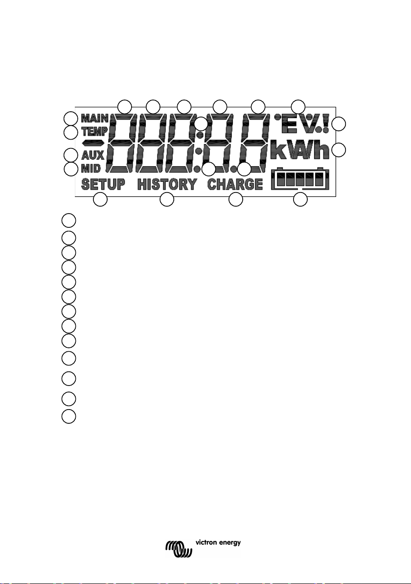
De waarde van het geselecteerde item wordt weergegeven met
deze cijfers
De accu moet worden opgeladen (vast) of de BMV synchroniseert
niet (knippert, samen met K)
Aanduiding laadstatus accu (knippert als niet wordt
gesynchroniseerd)
Eenheid van het geselecteerde item. bv. W, kW, kWh, h, V, %, A,
Ah, °C, °F
A
B C D E F G H I J K L M D E G
F
H I J
K
M A A A A A B C C
L
L
7 DISPLAY
Overzicht van het display van de BMV.
Dubbele punt
Decimaalteken
Symbool hoofdaccuspanning
Symbool accutemperatuur
Symbool hulpspanning
Symbool middelpuntspanning
Menu setup actief
Menu geschiedenis actief
Alarmaanduiding
Scroll-tekst
De BMV heeft een scroll-mechanisme voor lange teksten. De scrollsnelheid kan worden gewijzigd door de instelling ‘scroll speed’ in het
menu instellingen aan te passen. Zie paragraaf 4.2.4. parameter 51
40
Page 83

8 TECHNISCHE GEGEVENS
Voedingsspanningsbereik (BMV-700 / BMV-702) 6,5 … 95 VDC
Voedingsspanningsbereik (BMV-712) 6,5 … 70 VDC
Voedingsspanningsbereik (BMV-700H) 60… 385 VDC
Voedingsstroom (geen alarmsituatie, achtergrondverlichting uit)
BMV-700/BMV-702
BMV-712 Smart
BMV-700H
Ingangsspanningsbereik hulpaccu (BMV-702) 0 ... 95 VDC
Ingangsstroombereik (met meegeleverde shunt) -500 ... +500 A
Bedrijfstemperatuurbereik -20 ... +50 °C
Uitleesresolutie:
Spanning (0 ... 100 V) ± 0,01 V
Spanning (100 … 385 V) ± 0,1 V
Stroom (0 ... 10 A) ±0,01 A
Stroom (10 ... 500 A) ±0,1 A
Stroom (500 ... 9999 A) ±1 A
Ampère-uren (0 ... 100 Ah) ±0,1 Ah
Ampère-uren (100 ... 9999 Ah) ±1 Ah
Laadstatus (0 ... 100 %) ±0,1 %
Resterende tijd (0 ... 1 uur) ±0,1 uur
Resterende tijd (1 ... 240 uur) ±1 uur
Temperatuur ±1 °C/ °F
Vermogen (-100 ... 1 kW) ±1 W
Vermogen (-100 ... 1 kW) ±1 kW
Nauwkeurigheid spanningsmeting ±0,3 %
Nauwkeurigheid stroommeting ±0,4 %
Potentiaalvrij contact
Modus Configureerbaar
Standaardmodus Normaal open
Nominale waarde 1 A tot 30 VDC
0,2 A tot 70 VDC
1 A tot max 50 VAC
Afmetingen:
Voorpaneel 69 x 69 mm
Diameter behuizing 52 mm
Inbouwdiepte 31 mm
Nettogewicht:
BMV 70 g
Shunt
Materiaal
Behuizing ABS
Sticker Polyester
@Vin = 12 VDC 3 mA
Met spanningsvoerend relais 15 mA
@Vin = 24 VDC 2 mA
Met spanningsvoerend relais 8 mA
@Vin = 12 VDC 1 mA
Met spanningsvoerend relais n.v.t. (bistabiel relais)
@Vin = 24 VDC 0,8 mA
Met spanningsvoerend relais n.v.t. (bistabiel relais)
Omvang zekering op positieve draad 1 A, 20 x 5 mm.
@Vin = 144 VDC 3 mA
@Vin = 288 VDC 3 mA
315 g
EN NL FR DE ES SE Appendix
NL FR DE ES SE IT PT
41
Page 84

Page 85

1 MANUEL DE DÉMARRAGE RAPIDE
1.1 Capacité de batterie
1.2 Entrée auxiliaire (BMV-702 et BMV-712 Smart uniquement)
1.3 Fonctions importantes grâce à la combinaison de boutons
2 MODE D'EXPLOITATION NORMAL
2.1 Vue d'ensemble des lectures
2.2 Synchronisation du BMV
2.3 Problèmes habituels
3 CARACTÉRISTIQUES ET FONCTIONS
3.1 Caractéristiques des trois modèles BMV
3.2 Pourquoi contrôler sa batterie ?
3.3 Comment fonctionne le BMV ?
3.3.1 À propos de la capacité de batterie et du taux de décharge
3.3.2 Facteur d'efficacité de charge (CEF)
3.4 Différentes options d'affichage de l'état de charge de la batterie
3.5 Historique des données
3.6 Utilisation de shunts alternatifs
3.7 Détection automatique de la tension nominale du système
3.8 Alarme, sonnerie et relais
3.9 Options d'interface
3.9.1 Logiciel PC
3.9.2 Écran large et surveillance à distance
3.9.3 Intégration personnalisée (programmation nécessaire)
3.10 Fonctions supplémentaires du BMV-702 et BMV-712 Smart
3.10.1 Contrôle de batterie auxiliaire
3.10.2 Contrôle de température de la batteriec
3.10.3 Contrôle de la tension médiane
3.11 Fonctionnalité supplémentaire du BMV-712 Smart
3.11.1 Cycle de charge automatique à travers les éléments d’état
3.11.2 Allumer/Éteindre le Bluetooth
4 DÉTAILS DE CONFIGURATION
4.1 Utilisation des menus
4.2 Vue d'ensemble des fonctions
4.2.1 Paramètres de la batterie
4.2.2 Paramètres du relais
4.2.3 Paramètres de la sonnerie de l'alarme
4.2.4 Paramètres d'affichage
4.2.5 Divers
4,3 Historique des données
5 POUR EN SAVOIR PLUS SUR LA FORMULE DE PEUKERT ET LE
CONTRÔLE DU POINT MÉDIAN
6 BATTERIES AU PHOSPHATE DE LITHIUM-FER (LiFePO4)
7 AFFICHAGE
8. CARACTÉRISTIQUES TECHNIQUES
EN NL FR DE ES SE Appendix
NL FR DE ES SE IT PT
1
Page 86

Transport et stockage
Température de stockage : entre -40 °C et +60 °C
Précautions de sécurité
• Tout travail à proximité d'une batterie au plomb est
potentiellement dangereux. Ces batteries peuvent générer des
gaz explosifs. Ne fumez jamais et ne permettez aucune étincelle
ou flamme à proximité d'une batterie. Veillez à ce que l'air circule
librement autour de la batterie.
• Portez des vêtements et des lunettes de protection. Ne touchez
pas vos yeux lorsque vous travaillez à proximité des batteries.
Lavez-vous les mains après l'intervention.
• En cas de contact entre l'électrolyte et la peau ou les vêtements,
lavez-les immédiatement avec du savon et de l'eau. En cas de
contact avec l'œil, rincez tout de suite abondamment à l'eau
courante pendant au moins 15 minutes et consultez
immédiatement un médecin.
• Soyez prudent lors de l'utilisation d'outils métalliques à proximité
des batteries. La chute d'un outil métallique sur une batterie peut
provoquer un court-circuit et éventuellement une explosion.
• Retirez tout objet personnel en métal tel que bague, bracelet,
collier et montre pour toute intervention près d'une batterie. Une
batterie peut produire un court-circuit assez élevé pouvant faire
fondre les objets comme une bague, et provoquer de graves
brûlures.
• Stocker l’appareil dans un endroit sec.
•
2
Page 87

1 MANUEL DE DÉMARRAGE RAPIDE
Ce manuel de démarrage rapide suppose que le contrôleur de batterie
BMV est installé pour la première fois, ou que les paramètres d'usine ont
été rétablis.
Pour des suggestions de câblage, voir l’annexe à la fin de ce manuel.
Les réglages en usine sont adaptés à la plupart des batteries au plomb :
électrolyte liquide, électrolyte gélifié ou AGM.
Le BMV détectera automatiquement la tension nominale de la batterie, dès
que l'assistant de configuration aura pris fin (pour en savoir plus sur les
détails et limites de la détection automatique de la tension nominale, voir
section 3.8).
Par conséquent, les seuls paramètres devant être configurés sont ceux de
la capacité de la batterie (BMV-700 et BMV-700H), et la fonctionnalité de
l'entrée auxiliaire (BMV-702 et BMV-712).
Veuillez installer le BMV en suivant le manuel d'installation rapide.
Après avoir installé le fusible sur le câble d'alimentation positive allant à la
batterie principale, le BMV lancera automatiquement l'assistant de
configuration.
L'assistant de configuration doit avoir terminé avant de pouvoir déterminer
d'autres paramètres. Sinon, utilisez l'application VictronConnect et un
smartphone.
Remarques :
a) Dans le cas des applications solaires ou des batteries au lithium-
ion, plusieurs paramètres devront peut-être être modifiés : Veuillez
consulter la section 2.3 et la section 6 respectivement. L'assistant de
configuration ci-dessous doit avoir terminé avant de pouvoir déterminer
d'autres paramètres.
b) Si un shunt, autre que celui fourni avec le BMV, est utilisé,
veuillez consulter la section 3.6. L'assistant de configuration doit avoir
terminé avant de pouvoir déterminer d'autres paramètres.
c) Bluetooth
Utilisez un appareil disposant de Bluetooth Smart (smartphone ou
tablette) permettant une configuration initiale facile et rapide, pour
modifier des paramètres ou pour une surveillance en temps réel.
BMV-700 ou 702 : Clé électronique VE.Direct – Bluetooth Smart
nécessaire.
BMV-712 Smart : Bluetooth activé, aucune clé électronique nécessaire.
Consommation d'énergie très faible.
3
EN NL FR DE ES SE Appendix
NL FR DE ES SE IT PT
Page 88
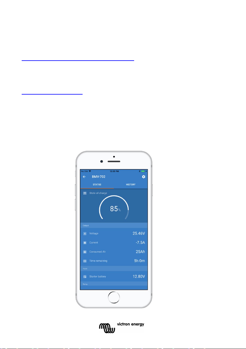
Bluetooth :
Clé électronique VE.Direct – Bluetooth Smart : consulter le manuel sur
notre site Web
Clé électronique VE.Direct-Bluetooth Smart
BMV-712 Smart :
Téléchargez l'application VictronConnect (voir la rubrique
Téléchargements sur notre site Web)
Manuel VictronConnect
Procédure d'association : le code PIN par défaut est 000000
Après la connexion, le code PIN peut être modifié en appuyant sur le
bouton (i) en haut à droite de l'application.
Si vous perdez le code de la clé électronique, réinitialisez-le à 000000 en
laissant le bouton Effacer PIN appuyé jusqu'à ce que le voyant Bluetooth
bleu se mette à clignoter temporairement.
4
Page 89

Assistant de configuration (sinon, utilisez l'application VictronConnect et un
Smartphone)
:
1.1 Capacité de batterie (utilisez de préférence la puissance nominale
de 20 heures (C
20))
a) Après avoir inséré le fusible, l'écran affichera un texte déroulant
01 BATTERY CAPACITY
Si ce texte n'est pas affiché, appuyez sur SETUP et SELECT en même
temps pendant 3 secondes pour rétablir les paramètres d'usine ou
consultez la section 4 pour obtenir davantage de renseignements sur les
détails de configuration (le paramètre 64 – Bloquer la configuration – doit
être sur OFF pour rétablir les paramètres d'usine. Voir section 4.2.5).
b) Appuyez sur n'importe quel bouton pour arrêter le défilement du texte,
et la valeur par défaut
0200 Ah apparaîtra en mode édition : le premier chiffre
clignotera.
Saisissez la valeur souhaitée avec les boutons + et –.
c) Appuyez sur SELECT pour définir le chiffre suivant, de la même
manière.
Répétez cette procédure, jusqu'à ce que la capacité de batterie soit
affichée.
La capacité est automatiquement enregistrée dans une mémoire non
volatile quand le dernier chiffre a été spécifié en appuyant sur SELECT.
Un bip court confirme l'enregistrement.
Si une correction doit être apportée, appuyez de nouveau sur SELECT, et
répétez la procédure.
d) BMV-700 et 700H : appuyez sur SETUP, + ou – pour achever la
configuration avec l'assistant, et pour passer en mode d'exploitation
normal.
BMV-702 : appuyez sur SETUP, + ou – pour paramétrer l'entrée auxiliaire.
EN NL FR DE ES SE Appendix
NL FR DE ES SE IT PT
5
Page 90

1.2 Entrée auxiliaire (BMV-702 et -712 uniquement)
a) L'écran fera défiler
AUXILIARY INPUT.
b) Appuyez sur SELECT pour arrêter le défilement du texte, et l'écran LCD
affichera :
star t
Utilisez la touche + ou – pour sélectionner la fonction requise de l'entrée
auxiliaire :
START pour le contrôle de la tension de la batterie de démarrage.
pour le contrôle de la tension médiane du banc de batteries.
TEMP pour utiliser la sonde de température, en option.
Appuyez sur SELECT pour confirmer. Un bip court signale la confirmation.
c) Appuyez sur SETUP, + ou – pour achever la configuration avec
l'assistant, et pour passer en mode d'exploitation normal.
Le BMV est maintenant prêt à l'emploi.
Lorsque le BMV sera allumé pour la première fois, il affichera par défaut un
état de charge de 100 %. Voir la section 4.2.1, paramètre 70 pour modifier
ce comportement.
En mode normal, le rétroéclairage du BMV s'éteindra au bout de 60
secondes, si aucune touche n'est utilisée. Appuyez sur n'importe quelle
touche pour allumer le rétroéclairage.
Le câble avec la sonde de température intégrée doit être acheté
séparément (nº de référence : ASS000100000). Cette sonde de
température n'est pas échangeable avec d'autres sondes de température
Victron, comme celles utilisées avec les chargeurs de batterie ou les
Multis/Quattros.
1.3 Fonctions importantes grâce à la combinaison de boutons
(Voir également la section 4.1 : Utilisation des menus)
a) Rétablir les paramètres d'usine
Appuyez en même temps sans lâcher SETUP et SELECT pendant 3
secondes
b) Synchronisation manuelle.
Appuyez en même temps, sans lâcher les boutons de Flèche Haut et
Flèche Bas pendant 3 secondes.
6
Page 91

c) Couper l'alarme sonore
Une alarme est considérée comme reconnue si on appuie sur un bouton.
Cependant, l'icône d'alarme s'affiche tant que la condition d'alarme
persiste.
1.4 Options d'affichage des données en temps réel sur un
Smartphone
Grâce à la clé électronique Bluetooth Smart communicant avec VE.Direct,
les alarmes et données peuvent être affichées en temps réel sur des
Smartphones, tablettes et autres dispositifs Apple et Android.
Remarque :
Une clé électronique Bluetooth Smart communicant avec VE.Direct n’est
pas nécessaire pour le BMV-712 puisqu’il dispose d’une fonction
Bluetooth intégrée.
EN NL FR DE ES SE Appendix
NL FR DE ES SE IT PT
7
Page 92

2 MODE D'EXPLOITATION NORMAL
2.1 Vue d'ensemble des lectures
S'il est en mode d'exploitation normal, le BMV affiche un ensemble de
paramètres importants.
Les boutons de sélection + et – permettent d'afficher plusieurs lectures :
Tension de la batterie
Tension de batterie auxiliaire
BMV-702 et -712 uniquement, si l'entrée
auxiliaire est définie sur START.
Courant
Le courant actuel qui sort de la batterie (pôle
négatif) ou qui rentre dans la batterie (sans
pôle).
Puissance
La puissance extraite de la batterie (pôle
négatif) ou rentrant dans la batterie (sans
pôle).
8
Page 93

Ampères-heures consommés
La quantité d'Ah consommés depuis la
batterie
Exemple :
Si un courant de 12 A est tiré de la batterie pendant une période de 3
heures, l'écran affichera une lecture de -36,0 Ah.
(-12 x 3 = -36)
Remarque : trois tirets « --- » s’afficheront lorsque le BMV s’allumera en
état non synchronisé. Voir la section 4.2.1, paramètre 70.
État de charge :
Une batterie totalement pleine indique une
valeur de 100,0 %. Une batterie totalement
vide indique une valeur de 0,0 %.
Remarque : trois tirets « --- » s’afficheront lorsque le BMV s’allumera en
état non synchronisé. Voir la section 4.2.1, paramètre 70.
Autonomie restante :
Cette indication correspond à la durée
estimée pendant laquelle la batterie peut
alimenter la demande actuelle, avant de
devoir être rechargée.
L'autonomie restante affichée correspond au temps nécessaire pour
atteindre le plancher de décharge.
Voir 4.2.2, paramètre numéro 16.
Remarque : trois tirets « --- » s’afficheront lorsque le BMV s’allumera en
état non synchronisé. Voir la section 4.2.1, paramètre 70.
Température de la batterie
BMV-702 et -712 uniquement, si l'entrée
auxiliaire est définie sur TEMP.
La valeur peut être affichée en degrés Celsius ou en degrés Fahrenheit.
Voir section 4.2.5.
EN NL FR DE ES SE Appendix
NL FR DE ES SE IT PT
9
Page 94

Tension de la section supérieure du banc de batteries
BMV-702 et -712 uniquement, si l'entrée
auxiliaire est définie sur MID.
Comparez avec la tension de section inférieure pour vérifier l'équilibrage
des charges de la batterie.
Pour de plus amples renseignements sur le contrôle du point médian de
la batterie, consultez la section 5.2.
Tension de la section inférieure du banc de batteries
BMV-702 et -712 uniquement, si l'entrée
auxiliaire est définie sur MID.
Comparez avec la tension de section supérieure pour vérifier l'équilibrage
des charges de la batterie.
Écart du point médian du banc de batteries
BMV-702 et -712 uniquement, si l'entrée
auxiliaire est définie sur MID.
Écart en pourcentage de la tension médiane mesurée.
Écart en volts du point médian du banc de batteries
BMV-702 et -712 uniquement, si l'entrée
auxiliaire est définie sur MID.
Écart en volts de la tension médiane.
2.2 Synchronisation du BMV
Pour une indication précise de l'état de charge de la batterie, le contrôleur
de batterie doit être régulièrement synchronisé avec la batterie et le
chargeur. Pour ce faire, il est nécessaire de charger totalement la
batterie.
Dans le cas d'une batterie de 12 V, le BMV se réinitialise à
« complètement chargé » quand les « paramètres chargés » suivants
sont atteints : la tension dépasse 13,2 V et en même temps, le courant de
charge (de queue) est inférieur à 4,0 % de la capacité totale de la batterie
(par ex. 8 A pour une batterie de 200 Ah) pendant 3 minutes.
10
Page 95

Le BMV peut aussi être synchronisé manuellement si cela est nécessaire
(c'est à dire, configuré sur « batterie complètement chargée ») Cela peut
être fait en mode d'exploitation normal en appuyant en même temps sur
les boutons + et – pendant 3 secondes, ou en mode configuration en
utilisant l'option SYNC (voir section 4.2.1, paramètre numéro 10).
Par défaut, le BMV est configuré pour démarrer à l’état non synchronisé
et il indiquera un état de charge de 100 %. Ce comportement peut être
modifié : voir la section 4.2.1, paramètre 70.
Si le BMV ne se synchronise pas automatiquement, il faudra peut-être
régler la tension chargée, le courant de queue, et/ou la durée chargée.
Après une interruption de l'alimentation du BMV, le contrôleur de batterie
doit être systématiquement de nouveau synchronisé pour qu'il puisse
fonctionner correctement.
Une fois la première synchronisation réalisée (automatiquement ou
manuellement), le BMV conserve une trace du nombre de
synchronisations automatiques : voir la section 4.3 – article de l'historique
SYNCHRONISATIONS.
2.3 Problèmes habituels
Pas de signe de vie sur l'écran
Le BMV n'est probablement pas raccordé correctement. Le câble UTP
doit être correctement inséré aux deux extrémités, le shunt doit être
raccordé au pôle négatif de la batterie, et le câble d'alimentation positive
doit être raccordé au pôle positif de la batterie avec le fusible inséré.
Le cas échéant, la sonde de température doit être connectée au pôle
positif du banc de batteries (l'un des deux fils de la sonde sert également
de fil d'alimentation électrique).
Les courants de charge et décharge sont inversés.
Le courant de charge doit être affiché avec une valeur positive.
Par exemple : 1,45 A.
Le courant de décharge doit être affiché avec une valeur négative.
Par exemple : -1,45 A.
Si les courants de charge et décharge sont inversés, les câbles
d'alimentation sur le shunt doivent être inversés : voir le manuel
d'installation rapide.
EN NL FR DE ES SE Appendix
NL FR DE ES SE IT PT
11
Page 96

Le BMV ne se synchronise pas automatiquement
L'une des raisons possibles peut être que la batterie n'atteint jamais l'état
de charge complète.
Une autre possibilité est que la configuration de la tension chargée devrait
être réduite et/ou le paramètre de courant de queue devrait être augmenté.
Voir section 4.2.1.
Le BMV synchronise trop tôt.
Dans des systèmes solaires ou d'autres applications avec des courants
de charge fluctuants, les mesures suivantes doivent être prises pour
réduire la probabilité que le BMV se réinitialise de manière prématurée à
100 % de l'état de charge :
a) Augmentez la tension « pleine charge » légèrement en dessous de la tension de charge
d'absorption (par exemple : 14,2 V dans le cas d'une tension d'absorption de 14,4 V).
b) Augmentez le temps de détection de « pleine charge » et/ou réduisez le courant de
queue pour éviter une réinitialisation précoce due à des passages de nuages.
Voir section 4.2.1. pour des instructions de configuration.
Les icônes de Synchronisation et Batterie clignotent.
Cela signifie que la batterie n'est pas synchronisée. Chargez les
batteries et le BMV se synchronisera automatiquement. Si ce n'est pas
le cas, revoyez les paramètres de synchronisation. Ou, si vous savez
que la batterie est entièrement chargée, mais que vous ne voulez pas
attendre la synchronisation du BMV : appuyez sans relâcher les
boutons Haut et Bas jusqu'à ce que vous entendiez un bip.
Voir section 4.2.1.
12
Page 97
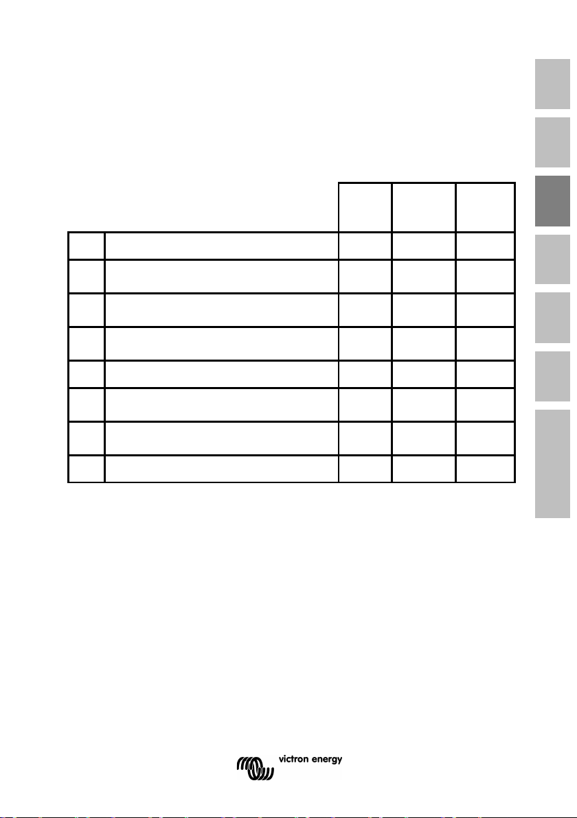
BMV
BMV
BMV
• • •
Contrôle de base d'une batterie
auxiliaire
•
Contrôle de température de la
batterie
•
Contrôle de la tension médiane du
banc de batteries
•
• • •
Détection automatique de la
tension nominale du système
• • •
Compatibles avec des systèmes à
haute tension
•
• • •
3 CARACTÉRISTIQUES ET FONCTIONS
3.1 Caractéristiques des quatre modèles BMV
Le BMV est disponible en 4 modèles chacun requérant un ensemble
différent de conditions d'utilisation.
EN NL FR DE ES SE Appendix
NL FR DE ES SE IT PT
-700
1 Suivi global d'une seule batterie
2
3
4
5 Utilisation de shunts alternatifs
6
7
8 Divers options d'interface
Remarque 1 :
Les caractéristiques 2, 3 et 4 sont mutuellement exclusives.
Remarque 2 :
Le câble avec la sonde de température intégrée doit être acheté
séparément (nº de référence : ASS000100000). Cette sonde de
température n'est pas échangeable avec d'autres sondes de température
Victron, comme celles utilisées avec les chargeurs de batterie ou les
Multis/Quattros.
-700H
-702
13
Page 98

3.2 Pourquoi contrôler sa batterie?
De nombreuses applications très diverses utilisent des batteries,
généralement pour stocker de l'énergie pour une utilisation ultérieure.
Mais, quelle quantité d'énergie est stockée dans la batterie ? Personne
ne peut le savoir juste en la regardant.
La durée de vie des batteries dépend de plusieurs facteurs. La durée de
vie d'une batterie peut être réduite pour des raisons diverses telles qu'une
charge trop faible, une surcharge, des décharges poussées excessives,
un courant de charge ou décharge excessif, et une température ambiante
élevée. En mettant la batterie sous la surveillance d'un contrôleur de
batterie sophistiqué, vous disposez d'informations essentielles pour agir
en temps utile. Ainsi, en prolongeant la durée de vie de la batterie, le
BMV sera rapidement amorti.
3.3 Comment fonctionne le BMV?
La principale fonction du BMV consiste à suivre et à indiquer l'état de
charge d'une batterie, et surtout à éviter une décharge totale inattendue.
Le BMV mesure en permanence le débit de courant qui entre ou qui sort
de la batterie. L'intégration de ce courant au fil du temps donne le
montant net d'Ah ajouté ou enlevé (si le courant est une quantité fixe
d'Ampères, il se réduit pour multiplier le courant et le temps).
Par exemple : un courant de décharge de 10 A pendant 2 heures prendra
10 x 2 = 20 Ah de la batterie.
Pour compliquer la situation, la capacité effective d'une batterie dépend
du taux de décharge et, dans une moindre mesure, de la température.
Et pour rendre les choses encore plus compliquées : en chargeant une
batterie, il faut « pomper » dans la batterie une quantité d'ampères
supérieure à celle pouvant être extraite lors de la prochaine décharge. En
d'autres mots : l'efficacité de charge est inférieure à 100 %.
3.3.1 À propos de la capacité de batterie et du taux de décharge
La capacité d'une batterie s'exprime en ampères-heures (Ah). Par
exemple, une batterie au plomb, capable de délivrer un courant de 5 A
pendant 20 heures, dispose d'une capacité de C
20 = 100 Ah (5 x 20 =
100).
14
Page 99

Si la même batterie de 100 Ah est déchargée entièrement en deux
heures, elle peut ne fournir que C
2 = 56 Ah (en raison de l'intensité de
décharge plus élevée).
Le BMV prend en compte ce phénomène avec la formule Peukert : voir
section 5.1.
3.3.2 Facteur d'efficacité de charge (CEF)
L'efficacité de charge d'une batterie au plomb est presque de 100 % tant
qu'aucune génération de gaz n'a lieu. Un dégagement gazeux signifie
qu'une partie du courant de charge n'est pas transformée en énergie
chimique stockée dans les plaques de la batterie, mais qu'elle est utilisée
pour décomposer l'eau en gaz oxygène et hydrogène (hautement
explosif !). Les « ampères-heures » stockés dans les plaques peuvent
être récupérés lors de la prochaine décharge alors que les « ampèresheures » utilisés pour décomposer l'eau sont perdus.
Les dégagements gazeux peuvent être facilement observés dans les
batteries à électrolyte liquide. Notez que la fin de la phase de charge,
« seulement oxygène », des batteries à électrolyte gélifié sans entretien
(VRLA) et des batteries au plomb, entraîne aussi une efficacité de charge
réduite.
Une charge d'efficacité de 95 % signifie que 10 Ah doivent être transférés
à la batterie pour obtenir réellement 9,5 Ah stockés dans la batterie.
L'efficacité de charge d'une batterie dépend du type de batterie, de son
ancienneté et de l'usage qui en est fait.
Le BMV prend en compte ce phénomène avec le facteur d'efficacité de
charge : Voir section 4.2.2, paramètre numéro 06.
3.4 Différentes options d'affichage de l'état de charge de la batterie
Le BMV peut afficher à la fois les ampères-heures extraits (lecture de
« Ampères-heures consommés » compensés pour l'efficacité de charge
seulement) et l'état de charge réel en pourcentage (lecture de « état-decharge », compensé par l'efficacité de charge et le rendement Peukert).
La meilleure façon d'évaluer la capacité de votre batterie est de contrôler
l'état de charge.
L BMV évalue également combien de temps la batterie peut supporter la
charge présente : il s'agit de la lecture d'autonomie restante. C'est le temps
qui reste actuellement jusqu'à ce que la batterie atteigne la limite de
décharge. Le paramètre par défaut pour la limite de décharge est 50 %
(voir section 4.2.2, paramètre numéro 16).
Si la demande en énergie varie fortement, il vaut mieux ne pas se fier à
cette indication puisqu'il s'agit d'une valeur passagère, qui ne doit servir
qu'à titre indicatif. Nous recommandons vivement l'utilisation de
EN NL FR DE ES SE Appendix
NL FR DE ES SE IT PT
15
Page 100

l'information de l'état de charge pour une surveillance précise de la
batterie.L’indicateur d’état de charge de la batterie (voir le chapitre 7
« Affichage ») évolue entre le seuil de décharge configuré et l’état de
charge à 100 %, et il reflète le véritable état de charge.
3.5 Historique des données
Le BMV enregistre les évènements pouvant être utilisés ultérieurement
pour évaluer des modèles d'utilisation et l'état de la batterie.
Sélectionnez le menu de l'historique des données en appuyant sur
ENTER, lorsque vous êtes en mode normal.
(voir section 4.3).
3.6 Utilisation de shunts alternatifs
Le BMV est livré avec un shunt de 500 A / 50 mV. Pour la plupart des
applications, cela devrait être suffisant. Cependant, le BMV peut être
configuré pour fonctionner avec une grande variété de différents shunts :
des shunts jusqu'à 9999 A et/ou 75 mV peuvent être utilisés.
Si vous utilisez un shunt autre que celui qui est fourni avec le BMV,
veuillez effectuer les étapes suivantes :
1. Dévissez la PCB du shunt fourni.
2. Montez la PCB sur le nouveau shunt, en vous assurant qu'il
existe un bon contact électrique entre la PCB et le shunt.
3. Connectez le shunt et le BMV tel qu'indiqué dans le manuel
d'installation rapide.
4. Suivez les étapes de l'assistant de configuration (section 1.1 et
1.2).
5. Une fois la configuration à l'aide de l'assistant terminée,
paramétrez le courant et la tension du shunt conformément à la
section 4.2.5, paramètres numéro 65 et 66.
6. Si le BMV lit un courant autre que zéro, alors qu'aucune charge
n'est présente et que la batterie n'est pas en cours de charge :
étalonnez la lecture de courant Zéro (voir la section 4.2.1,
paramètre numéro 09).
3.7 Détection automatique de la tension nominale du système
Le BMV s'ajustera automatiquement à la tension nominale du banc de
batterie, dès que la configuration à l'aide de l'assistant aura pris fin.
16
 Loading...