

Page 1
Model: VH-35
DUNE
BLUETOOTH SPEAKER SIDE TABLE
Page 2

CONTENTS
IMPORTANT SAFETY INSTRUCTIONS..................................................................................... 2
ACCESSORIES INCLUDED........................................................................................................ 4
ASSEMBLING YOUR FURNITURE ............................................................................................5
INSTALLING THE TIPPING RESTRAINT...................................................................................6
POWERING THE UNIT................................................................................................................ 7
PRODUCT OVERVIEW ...............................................................................................................8
LED STATUS ............................................................................................................................... 9
REMOTE CONTROL .................................................................................................................10
GENERAL OPERATIONS.......................................................................................................... 11
USB OPERATION...................................................................................................................... 12
BLUETOOTH OPERATION.......................................................................................................12
HDMI OPERATION....................................................................................................................13
CONNECTING OTHER DEVICES.............................................................................................14
AUX-IN OPERATION .......................................................................................................... 14
OPTICAL OPERATION ....................................................................................................... 14
COAXIAL OPERATION ....................................................................................................... 14
BLUETOOTH MULTI-PAIR FEATURE .....................................................................................15
SPECIFICATIONS .....................................................................................................................18
TROUBLESHOOTING GUIDE................................................................................................... 19
1
Page 3

1. Read these instructions - All the safety and operating instructions should be read before this
product is operated.
2. Keep these instructions - The safety and operating instructions should be retained for future
reference.
3. Heed all warnings - All warnings on the appliance and in the operating instructions should be
adhered to.
4. Follow all instructions - All operating and use instructions should be followed.
5. Do not use this apparatus near water - The appliance should not be used near water or moisture - for
example, in a wet basement or near a swimming pool, and the like.
6. Clean only with a dry cloth.
7. Do not block any ventilation openings. Install in accordance with the manufacturer’s instructions.
8. Do not install near any heat sources such as radiators, heat registers, stoves, or other apparatus
(including ampliers) that produce heat.
9. Do not defeat the safety purpose of the polarized or grounding plug. A polarized plug has two blades
with one wider than the other. A grounding plug has two blades and a third grounding prong. The
wide blade or the third prong is provided for your safety. If the provided plug does not t into your
outlet, consult an electrician for replacement of the obsolete outlet.
10. Protect the power cord from being walked on or pinched particularly at the plugs, convenience
receptacles, and at the point where they exit from the apparatus.
11. Only use attachments/accessories specied by the manufacturer.
12. Use only with the cart, stand, tripod, bracket, or table specied by the manufacturer, or sold with the
apparatus. When a cart or rack is used, use caution when moving the cart/apparatus combination to
avoid injury from tip over.
13. Unplug the apparatus during lighting storms or when unused for long periods of time.
14. Refer all servicing to qualied personnel. Servicing is required when the apparatus
has been damaged in any way, such as power supply cord or plug is damaged, liquid
has been spilled or objects have fallen into the apparatus, has been exposed to rain or
moisture, does not operate normally, or has been dropped.
15.
IMPORTANT SAFETY INSTRUCTIONS
- This lightning ash with arrowhead symbol within an equilateral triangle is intended to alert the user to
the presence of non-insulated “dangerous voltage” within the product’s enclosure that may be of
sufcient magnitude to constitute a risk of electric shock.
- Warning: To reduce the risk of electric shock, do not remove cover (or back) as there are no userserviceable parts inside. Refer servicing to qualied personnel.
- The exclamation point within and equilateral triangle is intended to alert the user to the presence of
important operating and maintenance instructions in the literature accompanying the appliance.
2
Page 4

16. The mains plug is used as disconnect device, the disconnect device shall remain readily operable.
17. CAUTION: To reduce the risk of re or electric shock, do not expose this apparatus to rain or
moisture. The apparatus shall not be exposed to dripping or splashing and that no objects lled with
liquids, such as vases, shall not be placed on apparatus.
18. Use the equipment in a moderate climate.
19. WARNING: To prevent electric shock, do not use this (polarized) plug with an extension cord,
receptacle or other outlet unless the blades can be fully inserted to prevent blade exposure.
ERP II NOTE (ENERGY RELATED PRODUCTS)
This product complies with the European Commission on the Eco-design directive and its implementing
Regulations-Energy related products. 15 minutes (approx.) later without any input (except in FM mode),
the system will automatically enter standby mode. Follow the instruction manual to assume the operation.
3
Page 5
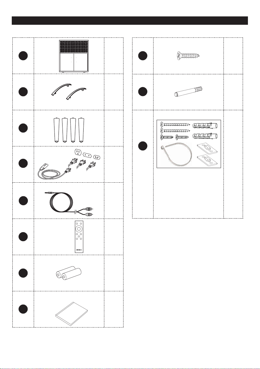
ACCESSORIES INCLUDED
Unpack the box and verify that the following items are included:
Main Unit
Screws
A
Handles
B X 2
Unit Legs
C X 4
Power Cords
*
D
RCA Cable
E
Remote Control
X 1
X 3
X 1
#1
Touch-up Pen
#2
Tipping Restraint Pack
#3
* One set includes 1 safety strap, 2 buckles,
2 rubber stoppers and 4 screws.
X 4
X 1
X 1
F
Batteries
G
User Manual
(Warranty Card inside)
H
Manual
X 1
X 2
X 1
Note: * D - three power cords with different plugs are included. Depending on your region, select and use
the appropriate one.
4
Page 6
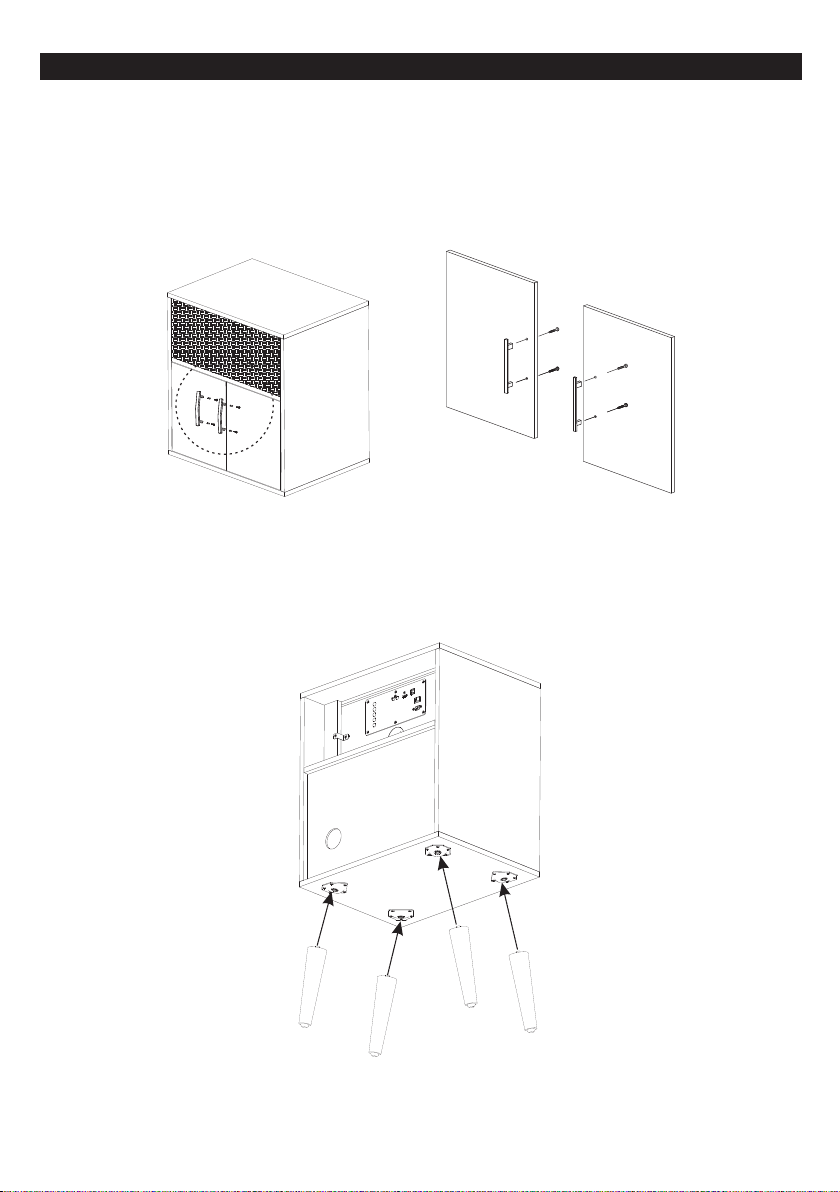
ASSEMBLING YOUR FURNITURE
IMPORTANT NOTE: Please make sure you have all parts before beginning assembly. Please wait until all
steps are completed before tightening bolts. Two people are recommended for assembly.
Step 1: Installing the Handles
Using the included handles, attach the handles into the doors’ holes as shown. Tighten 2 screws (included)
from the inside of the doors into the handles’ holes. (See picture inset.)
Step 2: Installing the Unit Legs
Lay the unit at on the oor, face the unit bottom (mounting position) to the side. Then attach the
legs (included) to the screw holes at the bottom of the unit and tighten them slowly.
Make sure the legs are xed rmly and place the unit back to the upright position. (See picture inset.)
CAUTION: This unit can support a MAXIMUM of 100 lbs
once it is assembled. Do not sit or stand on the unit.
5
Page 7
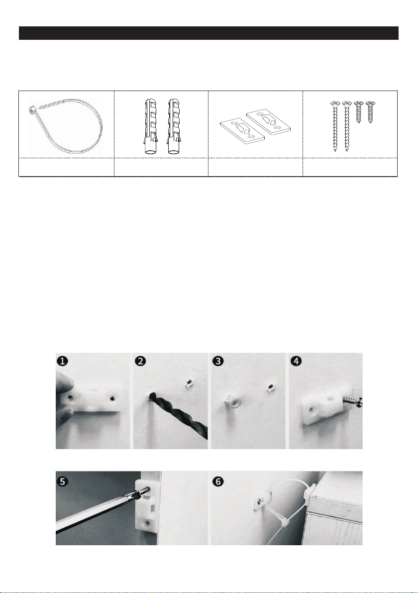
INSTALLING THE TIPPING RESTRAINT
Installing the Tipping Restraint helps to prevent the unit from tipping over.
* One tipping restraint package includes 1 safety strap, 2 brackets, 2 anchors and 4 screws.
Safety Strap X 1
Anchors X 2 Brackets X 2
Screws X 4
Installing the Tipping Restraint Pack
1. Determine the unit’s location in the room.
2. Figure out the placement of the tipping restraint bracket on the wall and mark the screw holes.
3. Use a small drill bit (not included), about 1/16 inch, and drill a small pilot hole to see if there is
a stud on the wall. If there is a stud, use the included long screws to attach the bracket to the wall.
(If there is no stud in the wall, drill a hole with a larger 1/4 inch drill bit (not included) and install the
included anchors.)
4. On the back of the unit, a bracket will need to be attached. To do this, temporarily move the
unit to its nal position and mark the location of the bracket on the unit.
5. Move the unit away from the wall and drill a pilot hole with a drill bit (not included) about
1/16 inch. Attach the bracket to the unit with the short screws (included).
6. Move the unit into its nal position, taking care to line up the wall brackets with the unit brackets.
Thread the safety strap (included) through the brackets as shown in picture-6 below. Tighten straps
until snug. Do not overtighten.
7. Check to be sure that the wall brackets are rmly screwed into the wall, and the unit brackets are
rmly attached to the frame, and the straps are snug.
MARK THE WALL
DRILL HOLES
INSTALL ANCHOR INSTALL SCREW
ATTACH BRACKET TO FURNITURE TIGHTEN STRAPS TO SECURE
6
Page 8

POWERING THE UNIT
CAUTION:
device or manufacturer
void your warranty.
1. Insert the AC Power Cord (included) into the AC INLET (AC IN) of the unit.
2. Connect the correct power cord to the wall socket.
Only use the AC Power Cords supplied with this device. Do not use a power supply from another
. Using any other power cords or power supply may cause damage to the device and
NOTE:
Three power cords with different
plugs are included. Depending
on your region, select and
use the appropriate one.
7
Page 9

Control Panel
PRODUCT OVERVIEW
2 3 456
1
1. NEXT
• Press to go to the next track.
Note: Function only supports Bluetooth and
USB modes.
• Hold the button for 3-5 seconds to increase
the volume level.
2. PLAY/PAUSE, PAIR
• Press once to pause the playback, press again
to resume.
Note: Function only supports Bluetooth
and USB modes.
• In Bluetooth mode, hold the button for 3-5 seconds to
disconnect the Bluetooth connection. Press the button
again to reconnect.
Note: The reconnect function only supports the devices
that connected with the unit before.
3. PREVIOUS
• Press to go to the previous track.
Note: Function only supports Bluetooth and
USB modes.
• Hold the button for 3-5 seconds to decrease the
volume level.
4. MODE/SOURCE
• Press the button repeatedly to switch to a different
playback mode.
• Hold the button for 3-5 seconds to set as an additional
unit. (Bluetooth Multi-Pair mode only)
5. STANDBY/ON-OFF
• Turn ON the unit or switch the unit to Standby mode.
• Hold the button for 3-5 seconds to set as the primary
unit. (Bluetooth Multi-Pair mode only)
7
8 9 10 11 12
13 14
6. AUX-IN JACK (R) / 7. AUX IN JACK (L)
• Use to connect devices with an RCA
cable (included).
8. COAXIAL-IN CONNECTOR
• Connect to the coaxial digital out device with
a coaxial cable (not included).
9. OPTICAL-IN CONNECTOR
• Connect to the optical digital out device with an
optical cable (not included).
10. HDMI (ARC) CONNECTOR
• Used to connect to the TV or HDMI equipment
with an HDMI cable (not included).
11. USB PLAYBACK PORT
• Connect USB storage devices.
Note: The maximum USB memory size is 32GB.
12. USB CHARGING PORT
• Use to charge your device with a USB cable.
13. AC INLET (AC IN)
• Used to connect the power cord (included).
Note: Three power cords with different plugs are
included. Depending on your region, select and
use the appropriate one.
14. POWER SWITCH
• Used to power ON or OFF the unit.
8
Page 10

LED STATUS
Status LED Indicators
(Hidden behind speaker grill)
LED Indicator-1
LED Indicator-2
Standard LED Status
Device Operation Mode LED Indicator-1 Action LED Indicator-2 Action
Standby Mode
Bluetooth Mode
AUX-IN Mode
Optical Input Mode
Coaxial Input Mode
HDMI (ARC) Mode
USB Play ba ck M od e
Note:
• The LED Indicator-1 & 2 will have different actions in Bluetooth Multi-Pair Feature. (See Page 15).
• The Indicators on the front of the unit will approximately stay on for 10 seconds. Press any button on the unit or
remote control to activate the LED.
RED (solid) –
Searching/Pairing: BLUE (blinks slowly) –
Connected: BLUE (solid) –
– ORANGE (solid)
– WHITE (solid)
RED (solid) WHITE (solid)
PURPLE (solid) –
BLUE (solid) ORANGE (solid)
9
Page 11

REMOTE CONTROL
Button Function
1. STANDBY/ON-OFF
• Turn ON the unit or switch the unit to Standby mode.
• Hold the button for 3-5 seconds to set as the Primary unit.
(Bluetooth Multi-Pair mode only)
2. MUTE
• Press Once to cut the playing volume in half.
• Press Twice to mute sound completely.
• Press a Third time to resume playing volume.
3. PREVIOUS / 7. NEXT
• Go to the previous/next track.
Note: Function only supports Bluetooth and USB modes.
4. PLAY/PAUSE, PAIR
• Press once to pause the playback, press again to resume.
Note: Function only supports Bluetooth and USB modes.
• In Bluetooth mode, hold the button for 3-5 seconds to disconnect the
Bluetooth connection. Press the button again to reconnect.
Note: The reconnect function only supports the devices connected
with the unit previously.
5. VOLUME+ / 6. VOLUME-
• Increase/decease the volume level.
8 NORMAL / 9. ROCK / 11. JAZZ / 12. POP
• Adjust the sound effect.
10. MODE
• Press button repeatedly to switch to different playback modes.
13
1
2
3
4
5
6
7
8
9
10
11
12
13. REACTION INDICATOR
• The indicator will ash red when pressing any buttons on the remote control.
Remote Control Operation
When the distance required for operation between the remote control and the unit decreases, it is
necessary to replace the batteries with new ones. The remote control is powered by 2 AAA batteries.
To replace the batteries, remove the battery cover on the back of the remote and remove the old batteries.
Replace with two new batteries according to the indicated polarity. Place the battery cover back on
the remote.
Battery Precautions
• Be sure to insert the batteries with correct positive “+” and negative “-” orientation. ALWAYS use
batteries of the same type. Never mix different types of batteries together.
• When using rechargeable batteries, refer to the precautions on their labels.
• When the remote control unit is not to be used for extended periods of time (more than a month),
remove the batteries to prevent them from leaking.
• Do not heat or disassemble batteries, and NEVER dispose of old batteries by throwing them in a re.
• Do not dispose of device into standard garbage disposal sites. Dispose of device at available Battery
Recycling Sites after fully discharging battery. Not doing so may violate disposal laws and regulations.
• Please refer to local regulations for proper battery disposal.
10
Page 12

GENERAL OPERATIONS
POWER ON THE DEVICE
Select an appropriate power cord (included) and plug it into the AC INLET (AC IN). Switch the POWER
SWITCH to ON. It is strongly recommended that this product should be operated only from the type of
power source marked on the rating label.
STANDBY
Press the STANDBY/ON-OFF button on the panel or remote control to turn on the unit or enter
Standby mode.
MODE
Repeatedly press the MODE button on the panel or remote control to change the playback modes:
Bluetooth, AUX-IN, Optical Input, Coaxial Input, HDMI (ARC) and USB Playback.
VOLUME+ & VOLUME-
Press the VOLUME+ or VOLUME- button on remote control to increase or decrease the volume level.
Note: There will be a chime when the volume reaches the maximum or minimum level.
MUTE
During playback, press the MUTE button on the remote control once and the volume will be cut in half.
Press twice to mute the sound. Press a third time to resume volume.
PLAY/PAUSE, PAIR
1. When playing in Bluetooth or USB mode, press the PLAY/PAUSE/PAIR button on the panel or
remote control to pause the playback, press again to resume.
2. In Bluetooth mode, hold the PLAY/PAUSE/PAIR button for 3-5 seconds to disconnect the
Bluetooth connection. Press the button again to reconnect.
Note: The reconnect function only supports the devices that were connected with the unit prior.
PREVIOUS & NEXT
When playing in Bluetooth or USB mode, press PREVIOUS or NEXT button on the panel or remote control
to skip to the next track or previous.
EQ FUNCTION (NORMAL / ROCK / POP / JAZZ)
Press the NORMAL, ROCK, POP or JAZZ button on remote control to adjust the sound effect.
IMPORTANT NOTES: The unit will auto switch to your last playback mode and settings when turned
on the next time.
11
Page 13

USB OPERATION
USB Playback:
1. Press the MODE button on the panel or remote control to enter USB mode. Once entered, the LED
Indicator-1 will be lit up in solid Blue and the LED Indicator-2 will be lit up in solid Orange at the
same time.
2. Plug the USB memory stick (not included) into the USB PLAYBACK PORT on the unit.
It will detect and playback automatically.
3. Control the playback from the unit or remote. Now you can enjoy the music from your USB.
Note:
• The maximum recommended USB memory size is 32GB.
• USB playback supports MP3 and WMA file formats.
USB Charging:
In any mode, you can charge your device
via the USB CHARGING PORT.
USB Storage
Device
BLUETOOTH OPERATION
1. Press the MODE button on the panel or remote control to enter Bluetooth mode. Once in Bluetooth
mode, the LED Indicator-1 will slowly blink blue
2. Go to Bluetooth settings on your device. Make sure your device’s Bluetooth feature is ON.
3. From the Bluetooth list on your device, select < VH-35 >. Once successfully connected, a chime will
be heard, and the LED Indicator-1 will stop blinking and be solid blue.
Notes: In some cases, password is required for your devices, input “0000" to connect.
4. Play the audio on your device, you will now hear audio from the unit.
a. To disconnect the Bluetooth connection, hold the PLAY/PAUSE/PAIR button for 3-5 seconds,
or press the MODE button to switch to another mode, or deactivate the Bluetooth function from
your device directly.
b. To reconnect, press the PLAY/PAUSE/PAIR button again. After successfully reconnecting,
press the button one more time to start the playback.
Note:
• The unit only reconnects to devices that were successfully connected before.
• Before reconnecting, please ensure there is no other Bluetooth connection to the unit.
12
Page 14

HDMI OPERATION
HDMI (ARC)
The ARC (Audio Return Channel) function allows you to send audio from your ARC-compliant TV to your
unit through a single HDMI connection. To use the ARC function, please ensure your TV is ARC compliant
and set up accordingly. The setting method of ARC may differ depending on your TV model. For details
regarding the ARC function, please refer to your TV owner’s manual.
Using HDMI (ARC)
1. Connect the HDMI cable (not included) from the HDMI ARC port of this unit to the HDMI ARC port on
your ARC compliant TV.
2. Ensure the unit is powered on. Press the MODE button repeatedly on the remote control or the unit itself
until the LED indicator-1 is lit up Purple.
3. Once successfully connected, the sound from your TV can be played directly from the unit.
Note:
• Only V1.4 or V2.0 version for the HDMI Cable can be used for this unit.
• Your TV needs to be compatible with the ARC function.
IMPORTANT: While in HDMI (ARC) mode, if there is no sound output, you may need to activate PCM
output on your source device (eg. TV, DVD, or Blu-ray player). Please refer to your source device’s owner’s
manual for activating PCM.
HDMI (ARC)
TV
13
Page 15

CONNECTING OTHER DEVICES
Connecting an audio
playback device
Connect to COAXIAL-IN, OPTICAL-IN
or AUX-IN input to an audio playback
device (CD player, portable music
player, etc.) using the appropriate cables.
AUDIO
OUTPUT
COAXIAL
OUTPUT
Audio Device
OPTICAL
OUTPUT
AUX-IN OPERATION
1. Press the MODE button on the panel or remote control to enter AUX-IN
Indicator-2 will be lit up in a solid Orange color.
2. Connect the unit with an RCA cable (included).
Make sure it is White to White and Red to Red. Then connect the other end of the cable to your device.
3. Control the playback from your device.
mode. Once entered, the LED
OPTICAL OPERATION
1. Press the MODE button on back panel or remote control to enter OPTICAL Input mode. Once entered,
the LED Indicator-2 will be lit up in a solid White color.
2. Use a digital optical cable (not included) to connect your television’s optical digital output to the unit’s
OPTICAL INPUT CONNECTOR.
3. Other components connected to the television, such as a DVD/Blu-ray player or cable/satellite tuner,
will automatically play through the unit.
COAXIAL OPERATION
1. Press the MODE button on back panel or remote control to enter COAXIAL Input mode. Once entered,
the LED Indicator-1 will be lit in a solid Red and LED Indicator-2 in solid White at the same time.
2. Use an “RCA”-type cable (not included) to connect your television’s coaxial digital audio output to the
unit’s COAXIAL INPUT CONNECTOR.
3. Other components connected to the television, such as a DVD/Blu-ray player or cable/satellite tuner
will automatically play through the unit.
14
Page 16

BLUETOOTH MULTI-PAIR FEATURE
This unit can pair with over 8 Victrola furniture pieces simultaneously for total surround sound.
How to Set Up Two Or More Units with the Bluetooth Multi-Pair Feature:
1. Power on only one unit (The unit you want to set as your primary).
2. Hold the STANDBY/ON-OFF button on one of the speakers for 3-5 seconds to set it as the primary
unit. The two indicators on the primary unit will be with different actions in different playback modes
when successfully set.
Device Operation Mode LED Indicator-1 Action
Bluetooth Mode
AUX-IN Mode
Optical Input Mode
Coaxial Input Mode
HDMI (ARC) Mode
USB Playback Mode
Note: You can only set one primary unit.
BLUE (blinks slowly) WHITE (blinks slowly)
– ORANGE (blinks slowly)
– WHITE (blinks slowly)
RED (blinks slowly) WHITE (blinks slowly)
PURPLE (blinks slowly) –
BLUE (blinks slowly) ORANGE (blinks slowly)
LED Indicator-2 Action
3. Set other speakers as Additional units, one by one:
a. Switch the Additional unit to Bluetooth Mode.
b. Press and hold the MODE button for 3-5 seconds to set it as the Additional unit.
(*LED Indicator-1 blinks quickly in Blue and LED Indicator-2 blinks quickly in White).
It will search and pair with the primary unit automatically.
c. Once successfully paired, the two indicators on the additional unit will stop blinking and steadily
light up.
d. Repeat Step-a to Step-c if you want to pair additional units.
4.
After completing Step 3, select and operate playback modes from the primary unit, and the music will
synchronized to all the additional speakers.
Note:
• The Additional unit only can be set in Bluetooth mode. Once switched to other modes, it will be disconnected
from the primary unit and quit the Bluetooth Multi-Pair Feature automatically.
• If there is static/interference during playback, we suggest to have a distance of 2-3 meters between units
to avoid interference.
How to Disconnent:
1. Press and hold the STANDBY/ON-OFF button on the primary unit for 3-5 seconds to cancel the
Bluetooth Multi-Pair settings. It will switch back to the normal playback mode automatically.
2. Press and hold the MODE button on the additional units for 3-5 seconds to cancel the additional
speaker setting. Or you can press the MODE button directly to quit Bluetooth status and switch to
another audio mode.
3. At this time, you can reset the Bluetooth Multi-Pair Feature when connecting the units.
Note: The Bluetooth Multi-Pair settings will be saved and paired to each other automatically when you turn on the
unit the next time. Before reset, you must cancel the original setting first.
15
Page 17

Operation Mode While Using Bluetooth Multi-Pair:
(Make sure to set your primary and secondary units FIRST! See page 15)
IMPORTANT:
•
The mode can only be switched on the primary unit. If you change the mode on the addtional unit, the
Bluetooth Multi-Pair connection on the additional unit will be disconnected automatically.
• The volume level for the primary and additional unit is independently controlled. They need to be
adjusted separately. (Use a remote control directed at the primary unit to adjust volume. Then use
the same remote and point to each additional unit to adjust the volume.)
• To mute the sound for both the primary and additional units, press the MUTE button twice on the
remote facing the primary unit. (Press once to reduce the primary unit volume by half, while the
additional unit volume will stay unchanged.) If you press the MUTE button with the remote facing the
additional unit, only the additional unit will be muted by half and the primary unit will be unchanged.
• In Bluetooth and USB modes, press the PLAY/PAUSE button to pause or play both the primary
and additional units.
• In AUX-IN, Optical, Coaxial and HDMI modes, the PLAY/PAUSE and PREVIOUS/NEXT buttons have
no functions.
• Change the volume effect by activating the EQ function of the primary unit (press the NORMAL,
ROCK, POP or JAZZ button on the remote control facing the primary unit). The sound effect for the
additional units will be synchronized with the primary unit.
BLUETOOTH OPERATION:
1
. Press the MODE button of the primary unit to enter Bluetooth Mode, when in Bluetooth pairing status,
you can see the blue and white LED indicators on the primary unit will light up and start blinking.
2. You can now sear
is
3. Once the device is paired, an audible tone will sound from the Master unit.
4. Play audio from your Bluetooth device. Volume can be controlled on your source device and the
speakers. Once playing, the music will be synchronized with the additional units.
found, pair with the (VH-35
ch for the Primary unit (VH-35) using your external Bluetooth device. Once the device
).
USB OPERATION:
1. Press the MODE button on the primary unit to enter USB playback mode, and the blue and orange
LED indicators on the primary unit will light up and start blinking.
2.
Plug a USB memory stick (not included) into the USB PLAYBACK PORT of the primary unit, and it will
start to
same time.
3. Control the playback on the primary unit.
AUX-IN OPERATION:
1. Press the MODE button of the primary unit to enter AUX-IN Mode. The orange LED indicator on the
primary unit will light up and start blinking.
2. Connect an RCA audio cable to the primary unit.
3. Start and control the playback from your device or the primary unit. The music on the additional
units will be synchronized with the primary unit.
play the music from the USB automatically on the primary and the additional units at the
16
Page 18

OPTICAL OPERATION:
1. Press the MODE button of the primary unit to enter Optical Mode. The white LED indicator on the
primary unit will light up and start blinking.
2. Use a digital optical cable (not included) to connect your television’s optical digital output to the
OPTICAL INPUT JACK on the primary unit. Other components connected to the television, such as
a DVD/Blu-ray player or cable/satelite tuner, will automatically play through the primary and
additional units at the same time.
COAXIAL OPERATION:
1. Press the MODE button of the primary unit to enter Coaxial Mode. The red and white LED indicators
on the Primary unit will light up and start blinking.
2. Connect an “RCA”-type cable (not included) to connect your television and the primary unit.
3. Other components connected to the television, such as a DVD/Blu-ray player or cable/satelite tuner,
will automatically play through the primary unit and the additional units.
HDMI OPERATION:
1. Press the MODE button of the primary unit to enter HDMI Mode. The purple LED indicator on the
primary unit will light up and start blinking.
2. Connect your television and the primary unit with an HDMI Cable (not included).
3
. Once successfully connected, the primary unit and additional units will start playing at the same time.
4. Control the playback on the primary unit.
BLUETOOTH MULTI-PAIR TROUBLESHOOTING:
- If you are having trouble pairing multiple pieces of furniture together, follow the easy troubleshooting
steps below:
1. Turn off your Bluetooth settings on any external devices and forget any previous paired Victrola
furniture devices.
2. Turn off all pieces of furniture.
3. Turn on the unit that will be the primary unit.
4. Go to Bluetooth mode on the furniture. If a single Blue LED is ashing, follow the instructions on page 15.
5. If there are two LED’s lit and ashing (blue and white), then press and hold the Standby button for
three seconds, until only one blue LED remains lit.
6. If there are still two lights lit, press and hold the Source button for 3 seconds.
Once the blue LED is blinking by itself, proceed to normal pairing steps on page 15.
*Follow the above steps 1-6 on each piece of furniture that was not connecting properly.
Note: If you have multiple units (multiple remotes) - one remote can be used to control all Victrola Furniture
pieces. Just point directly at the preferred unit to adjust settings.
17
Page 19

SPECIFICATIONS
GENERAL
Power Requirements.......................................................................... AC 100-240V~50/60Hz
Power Consumption .......................................................................... 80W
Unit Dimensions................................................................................. 21W x 15.7D x 30.2H (inches)
........................................................................................................... 533.4W x 399D x 767H (mm)
Unit Weight ........................................................................................ 90.39 lbs (23.8 kg)
(Max. supported weight: 100 lbs)
AMPLIFIER
Output Power..................................................................................... 2 x 20W + 40W
Frequency Response Subwoofer....................................................... 20 to 200 Hz
........................................................................................................... Mid-range tweeter:
200 Hz to 20 KHz
SPEAKER SYSTEM
Type ................................................................................................... 2.1ch
Impedance ......................................................................................... 4 Ohms
USB
USB Playback .................................................................................... 5V, 500mA
USB Charging .................................................................................... 5V, 2.1A
BLUETOOTH
Bluetooth Version............................................................................... Bluetooth V4.0
Bluetooth Proles............................................................................... A2DP, AVRCP
Bluetooth Frequency Range .............................................................. 2,402GHz - 2,480GHz
Operation Distance ............................................................................ 33 feet (10 meters)
18
Page 20

TROUBLESHOOTING GUIDE
Symptom Possible Cause Solution
• Unit will not power on. • Unit is unplugged.
• Unit will not turn on. • Power switch is not turned on. • Turn the power switch to On.
• No sound output from
speakers.
GENERAL
• Noise / Distortion in sound
output.
• Unit fails to respond.
• No sound
• Sound has a lot of static • Your device is too far away • Bring your device closer to the unit.
BLUETOOTH
• Unable to pair with a
Bluetooth device.
• Cannot use the Multi-Pair
connecting function.
BLUETOOTH
MULIT-PAIR
• The volume level is set too low.
• Mute the sound.
• The input selector does not match
the playback source.
• The unit is too close to another
interfering device.
• It might result from external factors
such as ESD (Electro-static
discharge).
• The unit is not switched to Bluetooth
Mode.
• Your device’s and/or the unit’s
volume is not turn on.
• Your device is too far from the unit
or there is some obstacle between
your device and the unit.
• Your device doesn’t have Bluetooth
connectivity.
• The Bluetooth pairing is not
successful.
• The primary / additional unit hasn’t
been set, or unsuccessful set.
• Connect the unit to the AC power
supply.
• Adjust the volume.
• Cancel the mute function.
• Select the correct input source.
• Turn off the other appliance, and
relocate the unit.
• Disconnect the power cord and
external audio device. Re-plug in the
power cord after one minute.
• Ensure the unit is switched to
Bluetooth mode.
• Move your Bluetooth device closer
to the unit.
• Turn up the volume on your portable
device and/or the unit.
• Turn OFF your Bluetooth device and
unit. Then power them both back ON.
• Conrm that your device is Bluetooth
compatible.
• Conrm that the unit is not paired
with another device.
• Re-pair the unit and device again.
• Make sure to cancel the BT Multi-Pair
connection before setting.
• Make sure the additional unit is set in
Bluetooth Mode.
For future assistance with your product, call Victrola at
TOLL FREE# 1-877-ITECH-97 (1-877-483-2497).
Please note: As a result of continual improvements, the design and specications of this product are
subject to change without notice.
Made in China.
Bluetooth is a registered trademark of Bluetooth SIG, Inc.Other trademark and track name are those
of their respective owners.
19
Page 21

FCC Statement
Warning: Changes or modications to this unit not expressly approved by the party responsible for compliance
could void the user authority to operate the equipment.
NOTE: This equipment has been tested and found to comply with the limits for Class B digital device, pursuant to
part 15 of the FCC Rules. These limits are designed to provide reasonable protection against harmful interference
in a residential installation. This equipment generates, uses and can radiate radio frequency energy and, if not
installed and used in accordance with the instructions, may cause harmful interference to radio communications.
However, there is no guarantee that interference will not occur in a particular installation. If this equipment does
cause harmful interference to radio or television reception, which can be determined by turning the equipment off
and on, the user is encouraged to try to correct the interference by one or more of the following measures:
- Reorient or relocate the receiving antenna.
- Increase the separation between the equipment and the receiver.
- Connect the equipment into an outlet on a circuit different from that to which the receiver is connected.
- Consult the dealer or an experienced radio/TV technician for help.
This device complies with Part 15 of the FCC Rules. Operation is subject to the following two conditions: (1) This
device may not cause harmful interference, and (2) this device must accept any interference received, including
interference that may cause undesired operation.
FCC Radiation Exposure Statement This equipment complies with FCC/IC radiation exposure limits set forth for
an uncontrolled environment. This equipment should be installed and operated with minimum distance 20cm
between the radiator & your body.
CALIFORNIA PROP 65 WARNING
WARNING: This product can expose you to chemicals including lead, which is known to the
State of California to cause cancer and birth defects or other reproductive harm.
For more information go to www.P65Warnings.ca.gov.
IC WARNING
-English:
This device contains license-exempt transmitter(s)/receiver(s) that comply with Innovation, Science and Economic
Development Canada’s license-exempt RSS(s). Operation is subject to the following two conditions:
(1) This device may not cause interference, and
(2) This device must accept any interference, including interference that may cause undesired operation of the
device.
-French:
Cet appareil contient des émetteurs / récepteurs exemptés de licence conformes aux RSS (RSS) d'Innovation,
Sciences et Développement économique Canada. L'exploitation est autorisée aux deux conditions suivantes:
(1) l’appareil ne doit pas produire de brouillage, et
(2) l'utilisateur de l'appareil doit accepter tout brouillage radioélectrique subi, même si le brouillage est susceptible
d'en compromettre le fonctionnement.
20
Page 22

Victrola is a registered trademark of Innovative Technology Electronics LLC.
Innovative Technology Electronics LLC.
Limited Warranty: 90 Days Labor, One Year Parts
Innovative Technology Electronics LLC. (IT) warrants the product to be free from “Defects” in materials
under normal use for a period of “One Year” from the date of the original purchase. The Warranty is “Not”
transferable. IT agrees, within the initial “90 Day” period, to repair or replace the product if it is determined
to be defective at “No Charge”. It is further agreed that IT will cover the cost to repair or replace damaged
“Parts” only for a total period of “One Year” from the date of the original purchase. The warranty does not
cover cosmetic damage, antennas, AC cords, cabinets, headbands, ear-pads, or damage due to line
power surges, connection to improper voltage supply or settings, misuse, mishandling, accident, acts of
God or attempted repair by an unauthorized service agent.
To obtain service, the purchaser MUST present an original sales receipt / proof of purchase. Please
contact us at www.victrola.com to request an RMA (Return Material Authorization) number to return
products for service or replacement. Returns without an RMA number on the package will be refused
and returned to sender. Upon receipt of the returning item and our full inspection (IT) may issue a
replacement to customer for the same item or of one that has equivalent value and features. To return an
item, supply full name, return address, phone number, item purchased, receipt of purchase and reason for
return to obtain RMA number.
All returns must be in the original packaging or reasonable substitute to prevent damage. Customer
“Must” include full name, shipping address and telephone number inside of package. No return will be
shipped back to a PO Box or APO address.
Please include your check or money order in the amount of:
• USD $5.00 for items $10.00 to $39.99. (Price Paid Per Unit)
• USD $10.00 for items $40.00 to $99.99. (Price Paid Per Unit)
• USD $16.00 for items $100.00 and up. (Price Paid Per Unit)
• Shipping fees are non-refundable.
to be payable to Innovative Technology Electronics LLC. (for handling and return shipping charges) (IT) will
not be responsible for delays or unprocessed claims resulting from a purchaser’s failure to provide any / all
of the necessary information. Send all inquiries or RMA request via our website
www.victrola.com/pages/technical-support.
Innovative Technology Electronics LLC.
1 Channel Drive
Port Washington, NY 11050
Toll free: 1-877-483-2497
Website for support: www.victrola.com/pages/technical-support
There are no express warranties except as listed above.
REPAIR OR REPLACEMENT AS PROVIDED UNDER THIS WARRANTY IS THE EXCLUSIVE REMEDY OF
THE CUSTOMER, (IT) SHALL NOT BE LIABLE FOR ANY INCIDENTAL OR CONSEQUENTIAL DAMAGES
FOR BREACH OF ANY EXPRESS OR IMPLIED WARRANTY ON THIS PRODUCT EXCEPT TO THE
EXTENT PROHIBITED BY APPLICABLE LAW. ANY IMPLIED WARRANTY OF MERCHANTABILITY OR
FITNESS FOR A PARTICULAR PURPOSE ON THIS PRODUCT IS LIMITED IN DURATION TO THE
DURATION OF THIS WARRANTY.
Some states do not allow the exclusion or limitation of incidental or consequential damages, or limitations
on how long an implied warranty lasts, so the above exclusions or limitations may not apply to you. This
warranty gives you specific legal rights and you may also have other rights, which vary from state to state.
21
 Loading...