

Victrix Zeus Superior 26/32kW Instruction Booklet
Page
Victrix Zeus Superior 26/32kW Instructions
Instruction Booklet
Eco-friendly wall-hung condensing boilers
with stainless steel storage tank
For Technical assistance, spare parts or service call:
RVR Limited, Kenmare, Co. Kerry Tel: 064 41344, Fax: 064 89520
Doc. Ref.: ALT112/070708
Read these instructions completely before using or installing the
Victrix Zeus Superior 26/32kW gas boilers
LEAVE THESE INSTRUCTIONS WITH THE USER
VICTRIX ZEUS Superior 26/32kW

Page 2
Victrix Zeus Superior 26/32kW Instructions
The Victrix Zeus Superior 26/32kW boilers are condensing wall hung, room sealed combination boilers incorporating a 54 litre stainless steel unvented hot water storage cylinder. This boiler has the highest efficiency possible for a gas boiler, i.e. 4 stars (****) in conformity with European Directive 92/42 EEC.
The boiler, providing both central heating and domestic hot water supply, is designed for use with a fully
pumped, sealed and pressurised heating system using Natural Gas or LPG. The boiler is supplied for use
with one of these gas types and must be converted before it can be used on another gas. A boiler equipped
for natural gas must not be used on LPG or vice versa.
The boiler is supplied with a pump, diverter valve, automatic bypass, pressure relief valve, expansion vessel
and pressure gauge fully assembled and tested.
As supplied, the boiler will automatically modulate to provide central heating outputs between 4.7 and
20.0kW for the 26kW model and 6.9 to 32kW for the 32kW model). The maximum output available for domestic hot water is 26.9 kW for the 26kW model and 33kW for the 32kW model and the boiler provides hot
water at temperatures of up to 60°C.
IMPORTANT
All gas appliances must be installed by a competent and qualified person, in accordance with relevant
clauses of applicable standards and recommendations. These include but may not be limited to the following:I.S. 813 Domestic Gas Installations
I.S, 820 Non-Domestic Gas Installations
All relevant Building Regulations.
Local Water Bye Laws
IEE Wiring Regulations
Health & Safety legislation
This appliance meets the requirements of IPX5D, i.e. degree of protection against moisture.
Failure to install this appliance correctly could lead to prosecution. It is in your own interest and that of
safety to ensure that the law is complied with. Manufacturer's instructions must NOT be taken in anyway as
over-riding statutory obligations.
Introduction
Page 3
Victrix Zeus Superior 26/32kW Instructions
Using the Boiler
Before lighting, make sure that the system is full of water and that the manometer (23) indicates a pressure of
1 - 1.2 bar.
Open the gas valve on the gas supply to the boiler.
The boiler is turned on and off by pressing button .
Press button A to switch to either Summer or Winter Heating.
N.B.: With button A set to summer, the central heating temperature setting is not active, and the domestic water temperature is controlled by selector (1). With the switch set to the central heating temperature is set using
selector (3) while selector (1) is used for the domestic hot water. Turn the selectors clockwise to raise the temperature, anticlockwise to lower it. Boiler operation is now automatic.
Button A - The boiler operating mode may be changed from the summer mode to winter mode by repeatedly
pressing button A. In summer mode, the DHW heating is active and central heating is not available. In winter
mode both central heating and direct hot water are available. The currently selected operating mode is shown
on the bottom of the LCD display.
Button B - Button B is used to override the hot water priority function B may be pressed until the DHW symbol
disappears from the left side of the LCD display. When this happens the boiler will function in central heating
mode only.
Button C is used to reset faults and also to exit the boiler menu system.
Selector switch (1) — used to adjust the DHW heating temperature from 20oC to 60oC. The set temperature is
displayed on the left side of the display during adjustment.
Selector switch (5) - used to adjust the central heating temperature from 25oC to 85oC. The set temperature is
displayed on the right hand-side of the LCD display during adjustment.
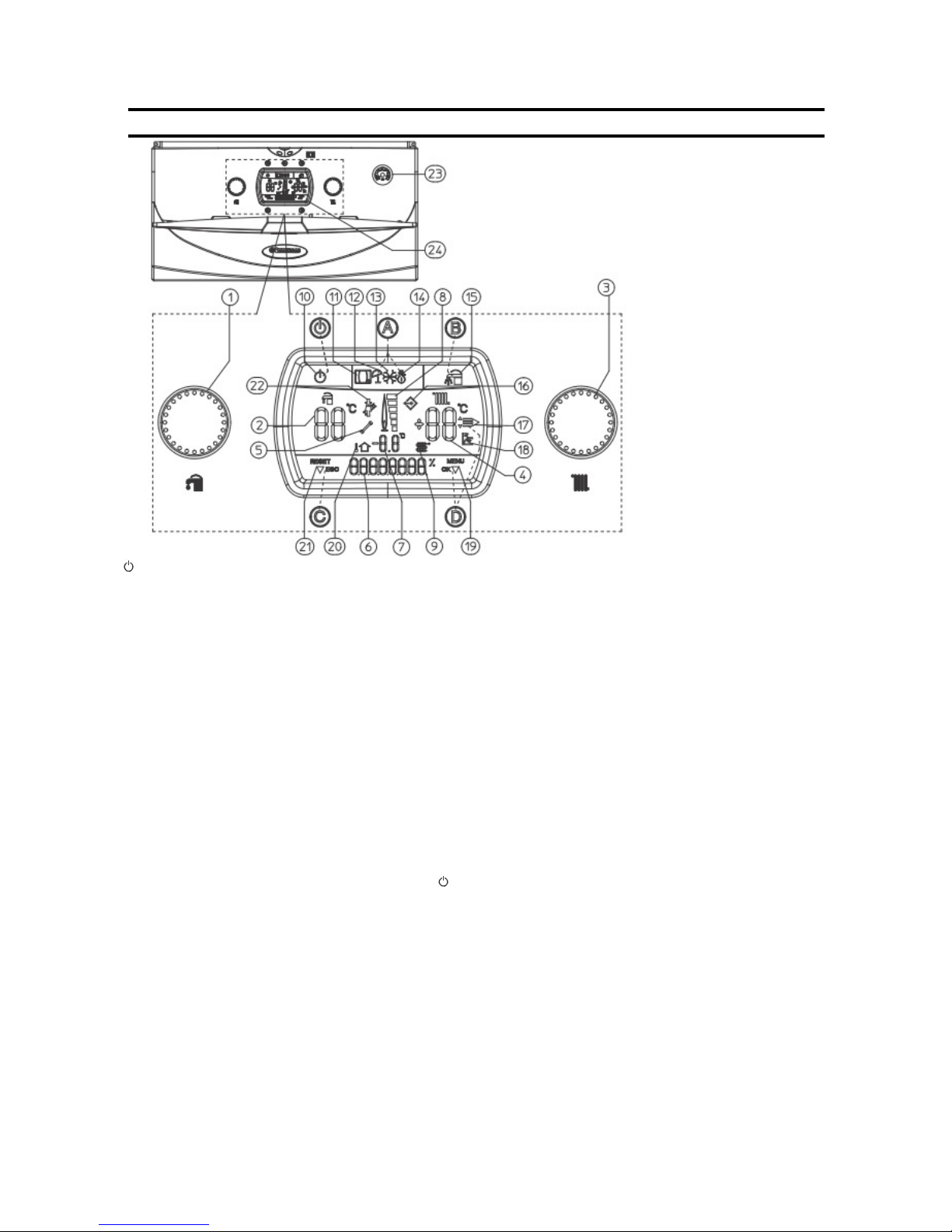
Boiler Operating Instructions
Figure 1– Boiler display
- Stand-by - On Button
A - Summer and winter
B - Domestic hot water priority Activation Button
C - (RESET) / menu exit (ESC) reset button.
D - Menu entry button (MENU)/ data confirmation (OK)
1 - Domestic hot water temperature selector switch
2 - Domestic hot water temperature set
3 - Central heating temperature selector switch
4 - Central heating temperature set
5 - Presence of faults
6 - Display of boiler functioning status
8 - Flame presence symbol and relative power scale
9 and 7 - Primary heat exchanger output water temperature
10 - Boiler in stand-by
11 - Boiler connected to remote control (Optional)
12 - Functioning in summer mode
13 - Anti-freeze function in progress
14 - Functioning in winter mode
15 - Domestic hot water priority functioning active
16 - Connection to external tools for technician
16 - Display of menu items
18 - Functioning with external temperature probe active
19 - Display of data confirmation or menu access
20 and 7 -External temperature display with external probe
connected (optional)
21 - Display of reset or exit menu request
22 - Chimney sweep function in progress
23 - Boiler manometer
24 - Multi-function display
Page 4
Victrix Zeus Superior 26/32kW Instructions
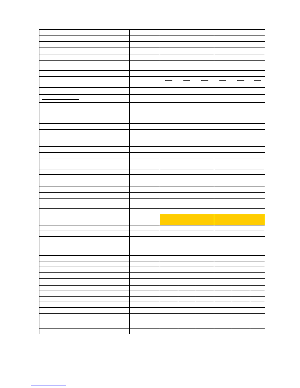
PERFORMANCE: Victrix Zeus Superior 26 Victrix Zeus Superior 32
Nominal Heat Input (DHW) Kw 26.9 33
Nominal Heat Output (Central Heating)
20.8 33
Min. Heat Input Kw 5.0 7.3
Nominal Heat Output (useful) (DHW) Kw 25.8 32
Nominal Heat Output (useful) (Central Heat-
ing)
20 32
Min. Heat Output (useful) Kw 4.7 6.9
GAS:
G20
G30
G31
G20
G30 G31
Nozzle diameter mm 5.7 4.1 4.1 - 6.0 6.0
Supply Pressure Mbar 20 29 37 20 29 37
HEATING SYSTEM:
Max Operating Pres. of Heating Unit bar 3
3
Max Operating Temp. of Heating Unit ºC 90
90
Adjustable Heat Temp (range 1) ºC 25 - 85 25-85
Adjustable Heat Temp (range 2) °C 25 - 50 25-50
Total Volume of heating expansion vessel l
7.1 7.1
Expansion Vessel precharge bar
1.0 1.0
Generator Water Capacity l 6.7
9.1
Total volume of DHW expansion vessel l 1.2 1.2
DHW expansion vessel pre-charge bar 2.5 2.5
Available head capacity 1000 l/h kPa 18.7 35.5
Working Heat Output d.h.w production Kw 26.9 33.0
DHW adjustable temperature ºC 20-60 20-60
Flow Limiting Device l/min
10 14
DHW circuit minimum pressure bar
0.3 0.3
DHW circuit max operating pressure bar
8 8
Specific capacity D according to EN6625 l/min
16 19.2
Continuous flow rate ∆T 30ºC l/min 13.1
15.3
Minimum pressure for flow limiting device
rated capacity
bar
1.0 1.0
Full boiler Weight kg 76.8 81.9
Empty boiler weight kg 70.1 72.8
ELECTRICAL:
Power Connection v/hz 230/50 230/50
Rated Power Input A 0.57 0.65
Installed Electrical Power W 110 135
Power absorbed by circulation pump W 74.7 98.6
Power absorbed by fan W 24.4 29
Appliance electrical system callout - IPX5D IPX5D
FLUE GASES:
G20 G30 G31 G20 G30 G31
Rated power fume mass flow kg/h 43 39 43 52 47 53
Minimum power fume mass flow kg/h 8 7 8
12
11 12
CO2 at nominal output % 9.4 12.0 10.6 9.4 12.3 10.5
CO2 at minimum output % 8.9 11.8 10.2 8.9 11.9 10.3
CO at O% O2 at nominal output ppm 200/7 670/11 270/7 206/9 640/8 190/8
NOx at 0% of 02 at nominal output ppm 39/22 108/50 43/30 47/24 158/51 57/30
Temperature of fumes at rated output (50/30) ºC 78 86 79 73 82 74
Temperature of fumes at min. output (50/30) ºC 73 82 75 64 72 66
Table 1— Technical Data

Page 5
Victrix Zeus Superior 26/32kW Instructions
Main Boiler Components
1 - System filling valve
2 - Condensate drain trap
3 - System draining valve
4 - Gas valve
5 - Three-way valve (motorised)
6 - 3 bar safety valve
7 - System pressure switch
8 - Boiler pump
9 - Vent valve
10 - Fan
11 - Gas nozzle
12 - Venturi
13 - Detection electrode
14 - Condensation module
15 - Flue safety thermostat
16 - Air intake pipe
17 - Sample points (air A) - (fumes F)
18 - Negative signal pressure point
19 - Burner
20 - Positive signal pressure point
21 - Manual vent valve
22 - Ignition electrodes
23 - System expansion vessel
24 - Flow probe
25 - Safety thermostat
26 - Domestic hot water probe
27 - D.H.W. expansion vessel
28 - Return probe
29 - Stainless steel cylinder
30 - 8 bar safety valve
31 - Cylinder draining valve
Gas
System
Return
System
Flow
DHW
Outlet
Cold water
inlet
Figure 2—Boiler Main Components
Page 6
Victrix Zeus Superior 26/32kW Instructions
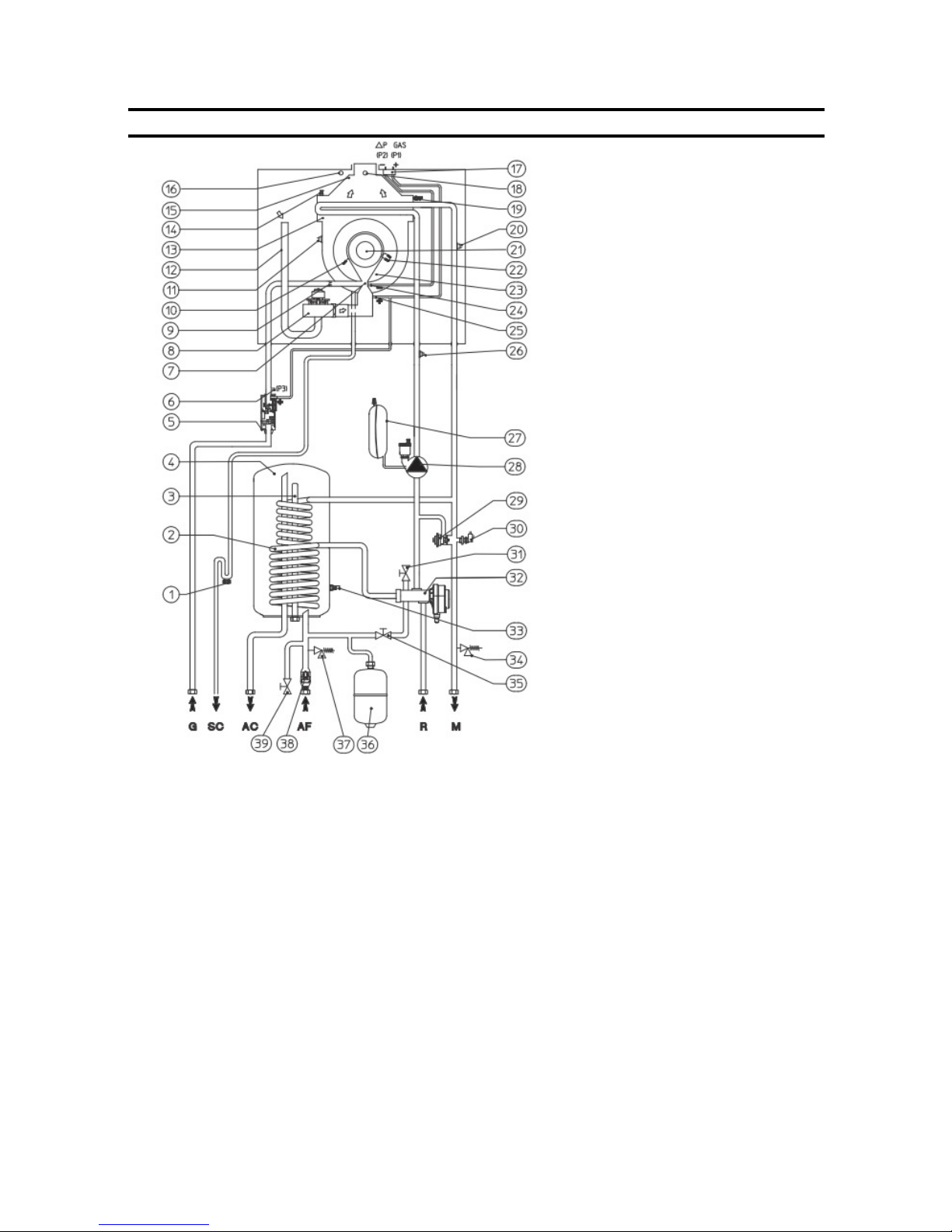
1 - Condensate drain
1 - Stainless steel coil for cylinder
3 - Magnesium anode
4 - Stainless steel cylinder
5 - Gas valve
6 - Gas valve outlet pressure point (P3)
7 - Air/gas Venturi collector
8 - Fan
9 - Gas nozzle
10 - Detection electrode
11 - Flue safety thermostat
12 - Air intake pipe
13 - Condensation module
14 - Manual vent valve
15 - Fumes hood
16 - Air sample point
17 - ∆p gas pressure point
18 - Flue sample point
19 - Flow probe
20 - Safety thermostat
21 - Burner
22 - Igniton electrodes
23 - Condensation module cover
23 - Venturi negative sign (P2)
25 - Venturi positive sign (P2)
26 - Return probe
27 - System expansion vessel
28 - Boiler pump
29 - Adjustable by-pass
30 - System pressure switch
31 - System draining valve
32 - Three-way valve (motorised)
33 - Domestic hot water probe
34 - 3 bar safety valve
35 - System filling valve
36 - D.H.W. expansion vessel
37 - 8 bar safety valve
38 - Cold water inlet non-return valve
39 - Cylinder draining valve
G - Gas supply
SC - Condensate drain
AC - Domestic hot water outlet
AF - Domestic hot water inlet
R - System return
M - System flow
Hydraulic Layout
Figure 3—Hydraulic Layout
Page 7
Victrix Zeus Superior 26/32kW Instructions
Gas Supply
The meter and supply pipes must be sized to deliver the gas rate and pressure given on page 4. The
boiler requires at least a 22 mm (3/4”) gas supply pipe. The complete installation, including the meter, must
be tested for gas soundness and purged as described in IS 813:2002.
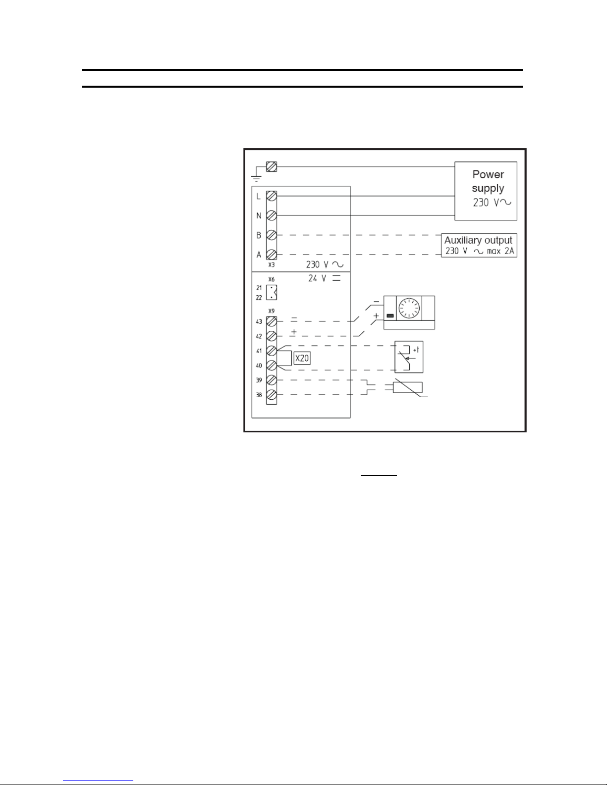
Electrical Installation
The boiler requires a 220/240 V ~ 50
Hz mains supply, fused at 3 A. The
boiler must be earthed. The polarity of the supply must be correct as
otherwise the boiler will not operate
properly.
There must only be one common isolator, providing complete electrical
isolation, for the boiler and any
external controls. Using PVC
insulated cable not less than 0.75
mm² (24 x 0.2 mm) to BS 6500
Table 16, the boiler should be
connected to a fused three pin plug
and unswitched shuttered socket outlet (both complying with BS 1363), or
a fused double pole switch with a
contact separation of at least 3 mm
in both poles.
Wiring external to the boiler must
be in accordance with the current IEE
Wiring Regulations.
Note: External controls connected to the boiler must be of the volt free type and are connected to
terminals 40 and 41 as shown above.
Weather Compensation
A temperature sensor for outdoors is available as an optional accessory for the boiler. This should be fitted
in an outdoor location which is not exposed to direct sunlight. A north facing wall is a good location.
If the optional weather compensation sensor is used, it should be connected to terminals 38 and 39 as
shown above using a two core cable. If this cable is routed in close proximity to cables carrying mains voltages, then screened cable should be used. Contact RVR for more information.
When the sensor is connected, the boiler adapts it’s flow temperature to suit the prevailing weather conditions. This results in lower energy usage and enhanced comfort.
WARNING ! - Connection of a voltage to any boiler terminals other than the mains
lead will result in destruction of the boiler control panel. The product warranty
does not cover this type of damage.
Clearances and Air Supply
The boiler does not require any air vents for cooling in the room in which it is installed or when installed in a
cupboard or compartment. The minimum clearances for servicing must always be maintained. Please see
table on page 14. Note: A cupboard or compartment used to enclose the boiler must be designed and
constructed specifically for the purpose.
General Installation Information
Optional Immergas
Remote controller
(CAR)
Replace link with volt free
contact from CH controls.
Do not connect 220V!
External weather com-
pensation sensor
Figure 4—Electrical Installation
Page 8
Victrix Zeus Superior 26/32kW Instructions
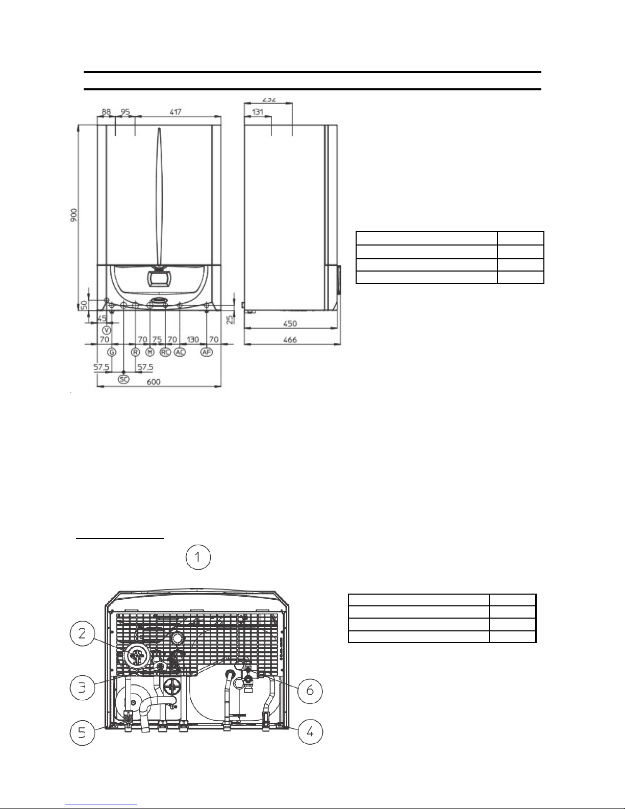
Boiler Dimensions
V - Electric connection
G - Gas supply
SC - Condensate drain (minimum internal diameter Ø 13 mm)
R - System return
M - System flow
RC - Domestic hot water pump (optional)
AC - Domestic hot water outlet
AF - Domestic hot water inlet
Height 900mm
Depth 466mm
Width 600mm
Boiler Dimensions
Gas Connection ½”
CH Connection ¾”
DHW Connection ½”
Boiler Connections
Boiler Connections
1 - Lower view
2 - System filling valve
3 - System draining valve
4 - Cold water inlet valve
5 - Gas cock
6 - Cylinder draining valve
Figure 5—Boiler Dimensions
Figure 6—Lower view
Page 9
Victrix Zeus Superior 26/32kW Instructions
Flue Systems
When the boiler is installed on an external wall, the standard horizontal concentric 60/100 flue kit will normally
be used to flue the boiler. This is shown in the diagram.
It is often necessary to install a longer flue system to cater for site conditions. There are several different flue
system sizes available for the Victrix Zeus 20/27 boiler.
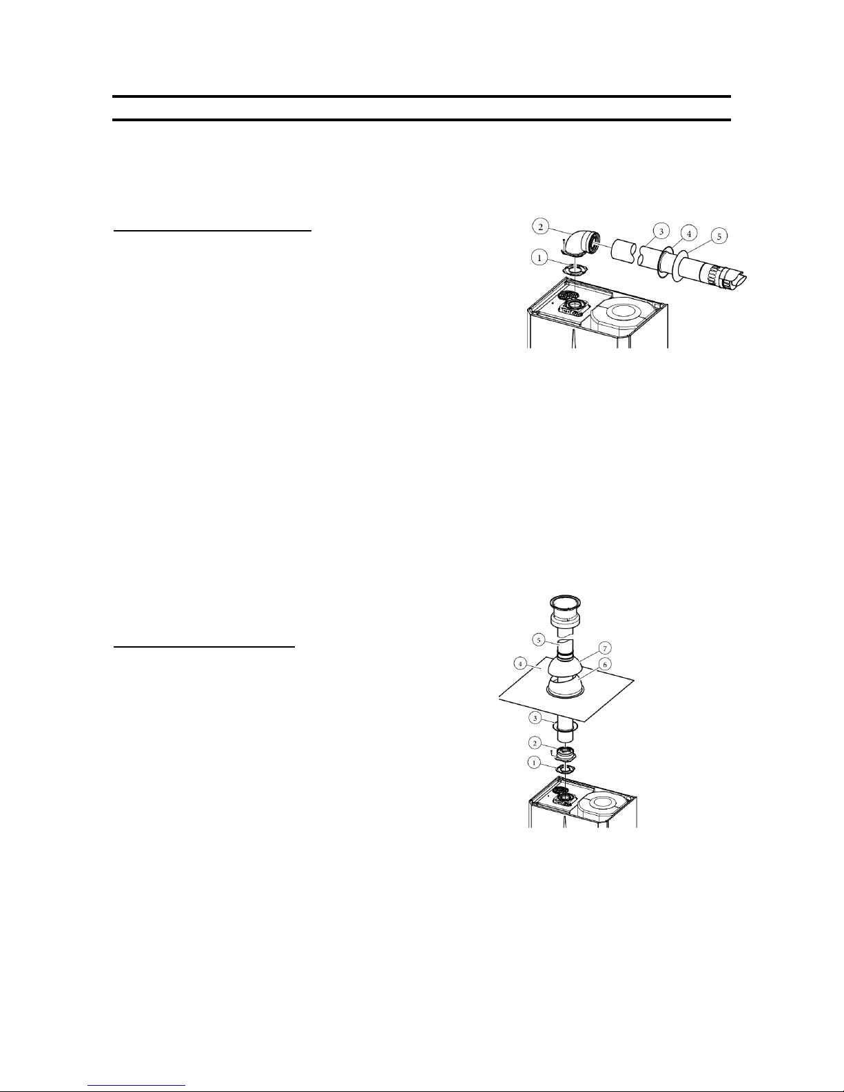
Horizontal concentric kit 60 /100
Install the bend with flange (2) on the left hole of the boiler inserting the seal (1) with the round protrusions facing downwards in contact with boiler flange and tighten using the screws supplied with
the kit.
Fit the smooth male end of the 60/100 concentric terminal pipe (3)
until it reaches to the stop on the female end of the bend (2), making sure the internal and external sealing rings are fitted; this will
ensure the connection is properly sealed. Additional extensions
and bends may be installed if required using the same method.
Ensure that all seals are fitted and that the outer and inner pipes
are installed so that all joints are perfectly sealed. Ensure that the
terminal is installed the right way up.
A lubricant may assist in overcoming the friction of the seals. Oils
and conventional greases are not compatible with the EPDM seals
used and should never be used for this purpose. Talc may be
used. Please contact RVR for more information.
A rigid supporting clamp should be fitted on each 1.0 metre or 2.0
metre flue extension in all cases. The flue system should be inclined at a minimum slope of 1% so that condensate flows towards the boiler. The elbow above the boiler is the low point of the flue system and the terminal at
the outside wall is the high point of the system. The fall should be continuous over the full length of the flue system and the there should be no low points which would allow condensate to build up within the flue pipes. This
avoids any drips from the external flue terminal.
The maximum possible overall length after the first bend (2)
is 12.9 straight and horizontal meters. See the section on
extended flue design for more information.
Vertical concentric kit 60 /100
Install the concentric flange (2) on the left hole of the boiler inserting the seal (1) with the round protrusions facing downwards
in contact with boiler flange and tighten using the screws supplied with the kit.
Fit the male end (smooth) of the adapter (3) in the female end of
the concentric flange (2) until it reaches the stop on the female
end of the flange, making sure the internal and external sealing
rings are fitted; this will ensure the connection is properly sealed.
Additional extensions and bends may be installed if required using the same method.
Installing the flashing- Replace tiles with the aluminium sheet (5),
shaping it to ensure that the rainwater runs off. Position the fixed
half-shell (7) on the aluminium tile and insert the intake/exhaust
pipe (6). Fit the male end (6)(smooth) of the 60/100 concentric
terminal up to the stop on the female end of the adapter(3),
making sure that the ring (4) is already fitted; this will ensure hold and joining of the elements making up the kit.
Ensure that all seals are fitted and that the outer and inner pipes are installed so that all joints are perfectly
sealed. A lubricant may assist in overcoming the friction of the seals. Oils and conventional greases are not compatible with the EPDM seals used and should never be used for this purpose. Talc may be used. Please contact
RVR for more information.
A rigid supporting clamp should be fitted on each 1.0 metre or 2.0 metre flue extension in all cases.
The maximum possible overall length including the terminal is 14.4 straight and horizontal meters.
NB: If the terminal or extension pipes need shortening ensure that the inner pipe protrudes by 5mm with
Figure 7—Horizontal concentric kit
Figure 8—Vertical concentric kit
The kit includes :
N° 1 - Gasket (1)
N° 1 - Female
concentric flange (2)
N° 1 - Wall sealing
plate (3)
N° 1 - Aluminium
tile (4)
N° 1 - Concentric
terminal int./exhaust
Ø
60/100 (5)
N° 1 - Fixed halfshell (6)
N° 1 - Mobile halfshell (7)
The kit includes:
N° 1 - Gasket (1)
N° 1 - Concentric bend Ø 60/100 (2)
N° 1 - Concentric terminal int./exhaust Ø
60/100 (3)
N° 1 - Internal white wall sealing plate (4)
N° 1 - External grey wall sealing plate (5)
Page 10
Victrix Zeus Superior 26/32kW Instructions
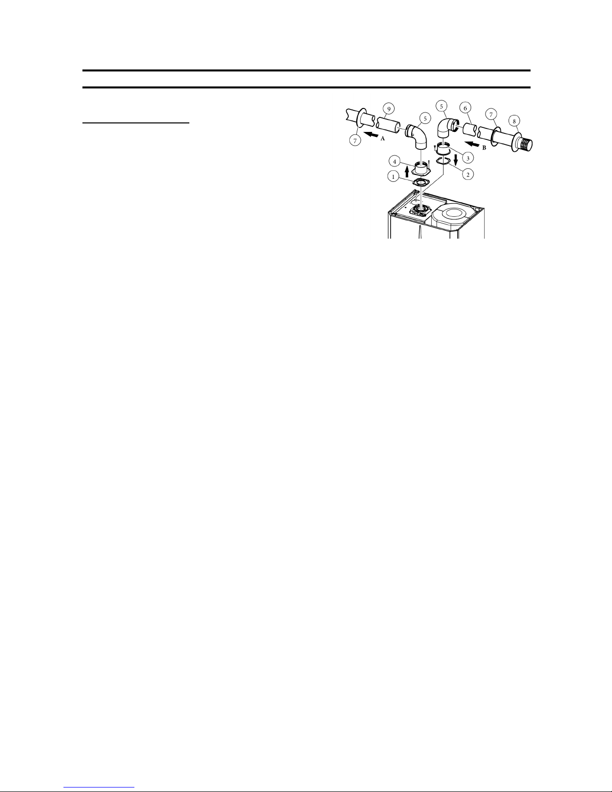
Separated 80/80 flue kit
This kit enables separation of the exhaust and air intake
pipes as shown in figure 9.
Combustion products are expelled from pipe (A) (in
plastic material resistant to acidic condensates). Air is
taken in through pipe (B) (also in plastic material) for
combustion.
Intake pipe (B) can be installed either on the right or left
hand side of the central exhaust pipe (B). Both pipes
can be oriented in any direction.
Assembly:
Install the flange (4) on the left hole of the boiler inserting the seal (1), positioning it with the round protrusions
downwards in contact with the boiler flange and tighten
using the screws supplied with the kit.
Remove the sealing plate from the air intake and replace it with flange (3)inserting seal (2) which is already
fitted on the boiler and tighten using the screws supplied.
Insert bends (5) with the male end (smooth) in the female end of the flanges (3&4). Fit the male end of the
intake terminal (6) up to the stop on the female end of
the bend (5), making sure that the relevant internal and
external sealing rings are fitted. Fit the male of the exhaust pipe up to the stop on the female end of the bend,
making sure that the internal sealing ring is fitted; this
will ensure a seal and joining of the elements making up
the kit.
Separated Flue Systems
A lubricant may assist in overcoming the friction of the seals. Oils and conventional greases are not compatible with the EPDM seals used and should never be used for this purpose. Talc may be used. Please
contact RVR for more information.
A rigid supporting clamp should be fitted on each 1.0 metre or 2.0 metre flue extension in all cases. The flue
system should be inclined at a minimum slope of 1% so that condensate flows towards the boiler. The elbow above the boiler is the low point of the flue system and the terminal at the outside wall is the high point
of the system. The fall should be continuous over the full length of the flue system and the there should be
no low points which would allow condensate to build up within the flue pipes. This avoids any drips from the
external flue terminal.
The maximum possible overall length without any bends is 36 straight, horizontal meters or 41
straight, vertical meters regardless of whether they are used in intake or exhaust. See the section
on extended flue design for more information.
Figure 9—Separated flue kit
The kit includes:
N° 1 - Exhaust gasket (1)
N° 1 - Flange seal (2)
N° 1 - Female intake flange (3)
N° 1 - Female exhaust flange (4)
N° 2 - Bend 90° Ø 80 (5)
N° 1 - Intake terminal Ø 80 (6)
N° 2 - Internal white wall sealing plates (7)
N° 1 - External grey wall sealing plate (8)
N° 1 - Exhaust pipe Ø 80 (9)
 Loading...