

Page 1

Blast Chiller Operator’s Manual
Reach-In Models: VBC-35, VBC-70, VBC-75 & VBC-100
Roll-In Models: VBC-175, VBC-220, VBC-350,VBC-480 & VBC-660
Manual Part No. 50850502
Rev: 00
Print Date: 11/5/04
RR ee ff rr ii gg ee rr aa tt ii oo nn aa tt ii tt ss bb ee ss tt
110 Woodcrest Road, Cherry Hill, NJ 08003
Phone: (856) 428- 4200 Fax: (856) 428-7299 Website: www.victory-refrig.com
E-Mail: parts@victory-refrig.com ● order-entry@victory-refrig.com ● service@victory-refrig.com
PART OF AGA FOODSERVICE GROUP
Page 2

Thank you for purchasing a Victory Refrigeration Reach-In or Roll-In Blast Chiller! This
unit has passed our strict Quality Control Inspection and meets the high standards set
by Victory Refrigeration. You have made a quality investment that with proper
maintenance will give you years of service.
Please read the following installation and maintenance instructions before installing or
using your unit. If you have any questions, please call our Customer Service
Department at (856) 428-4200.
IMPORTANT INFORMATION - PLEASE READ
●●
Please read these instructions carefully before installing or using. If recommended
procedures are not followed, warranty claims will be denied.
●●
Your Warranty Registration information is located on the next page of this manual. Please
complete the card and submit it to Victory Refrigeration within 10 days of installation.
Failure to properly register equipment can void the warranty.
●●
Victory Refrigeration reserves the right to change specifications and product design
without notice. Such revisions do not entitle the buyer to corresponding changes,
improvements, additions or replacements for previously purchased equipment.
●●
A detailed Owners Manual with a troubleshooting guide, parts lists and additional
information can be ordered from the factory or may be downloaded free from the website
at www.victory-refrig.com.
THANK YOU
Page 3
Warranty
(Continental USA Only)
The Seller warrants to the original purchaser, equipment manufactured by Seller to be free from defects in material and
workmanship for which it is responsible. The Seller's obligation under this warranty shall be limited to replacing or
repairing at Seller's option, without charge, F.O.B. Sellers factory, any part found to be defective and any labor and
material expense incurred by Seller in repairing or replacing such part, such warranty to be limited to a period of one
year from date of purchase or thirteen months from date of shipment from Seller's factory, whichever is earlier, provided
terms of payment have been fully met. All labor shall be performed during regular working hours. Overtime premium
charges will be at Buyer's expense.
Proof of purchase must be supplied to Seller to validate warranty. This warranty is valid only if equipment is properly
installed, started-up and inspected by the dealer or authorized Victory Service agent.
Removal or alteration of the serial/data plate from any equipment shall be deemed to release Seller from all warranty
obligations or any other obligations, expressed or implied.
This warranty does not cover Thermostat or Defrost Timer calibration and/or adjustment, freight damage, normal
maintenance items outlined in Owner's Manual, adjustment of door mechanisms or replacement of light bulbs, fuses
or batteries.
Any repairs or replacement of defective parts shall be performed by Seller's authorized service personnel. Seller shall
not be responsible for any costs incurred if the work is performed by other than Seller's authorized service personnel.
Reimbursement claims for part(s) or labor service costs must be made in writing. Model, cabinet serial numbers and
installation location must be shown on the claim. A receipted bill from the servicing agency must accompany the claim,
together with full details of the service problems, diagnosis and work performed. Victory reserves sole discretion
whether further documentation on a claim is to be submitted.
Seller shall not be liable for consequential damages of any kind which occur during the course of installation of
equipment, or which result from the use or misuse by Buyer, its employees or others of the equipment supplied
hereunder, and Buyer's sole and exclusive remedy against Seller for any breach of the foregoing warranty or otherwise
shall be for the repair or replacement of the equipment or parts thereof affected by such breach.
The foregoing warranty shall be valid and binding upon Seller if and only if Buyer loads, operates and maintains the
equipment supplied hereunder in accordance with the instruction manual provided to Buyer. Seller does not guarantee
the process of manufacture by Buyer or the quality of product to be produced by the equipment supplied hereunder
and Seller shall not be liable for any prospective or lost product or profits of Buyer.
THE FOREGOING WARRANTY IS EXCLUSIVE AND IN LIEU OF ALL OTHER EXPRESS AND IMPLIED
WARRANTIES WHATSOEVER. SPECIFICALLY THERE ARE NO IMPLIED WARRANTIES OF MERCHANTABILITY
OR OF FITNESS FOR A PARTICULAR PURPOSE.
The foregoing shall be Seller's sole and exclusive obligation and Buyer's sole and exclusive remedy for any action,
whether in breach of contract or negligence. In no event shall Seller be liable for a sum in excess of the purchase price
of the item.
ORIGINAL DATE OF INSTALLATION __________________________________________________________________
INSTALLATION COMPANY NAME ____________________________________________________________________
STREET_______________________________ CITY _____________________ STATE ______ ZIP CODE___________
DISTRIBUTOR’S NAME_____________________________________________________________________________
STREET_______________________________ CITY _____________________ STATE ______ ZIP CODE___________
You may register online at www.victory-refrig.com, fax this completed page to (856) 428-7299, or copy and mail form below to Victory.
*NOTE: The following mail-in form or online registration must be filled out and forwarded to Victory by the installer or customer within 10 days
after start-up. Failure to do this will invalidate the warranties. Retain this information for your records.
110 WOODCREST ROAD
CHERRY HILL, NJ 08003-3648
TEL: (856) 428-4200
● FAX: (856) 428-7299
Cabinet Model No.
______________________
Cabinet Serial No._________________
(Data plate information located inside cooler on
the upper left wall)
WARRANTIES NOT VALID UNLESS REGISTERED AT
FACTORY WITHIN 10 DAYS AFTER START-UP DATE.
Page 4

Page 5

TABLE OF CONTENTS
Page 2 Receiving Shipment
Unpacking
Installation
Electrical Supply
Start-Up
●●
Main Control Breakers
●●
Initial Start-Up Error Code & Checks
Page 3 Principals of Operation
Loading and Packing
Food Storage Time
Operation of Blast Chillers
Page 4 Operation of Blast Chillers (continued)
Defrost
Roll In Blast Chillers with Storage Pod
The Controls
Page 5 The Controls (continued)
Programming A Blast Chill Cycle
Alarm and Warning Levels
Page 6 Alarm and Warning Levels (continued)
The Printer
Page 7 Printer Set Up
Logger Paper Installation
Print Cartridge Removal & Installation
Page 8 Power Failure
Maintenance
●●
Cleaning
●●
Door Gasket
●●
Condenser Cleaning
Page 9 Technical Service & Replacement Parts
Rules of Thumb
Page 10 Before Calling Service Guide (for Common Problems)
Pages 11- 27 Parts Lists
Pages 28- 40 Wiring Diagrams
Page 6

Proper installation is the first step to operation. We recommend that your refrigerator or
freezer be installed by an authorized Victory Certified Installer.
RECEIVING SHIPMENT
All units are performance tested and thoroughly inspected prior to shipment. Upon leaving the factory,
all units are in perfect condition. Upon receipt, examine the exterior of the shipment packaging for any
signs of rough handling. If the cabinet is damaged, it should be noted on the delivery slip or bill of
lading and signed. A claim must be filed immediately against the carrier indicating the extent and
estimated cost of damage incurred.
UNPACKING
Remove all external and interior packing and accessories. Ensure all packaging is disposed of
safely.
INSTALLATION
The cabinet should stand level to ensure correct operation of self closing doors and proper drainage
of condensate from the evaporator.
Models fitted with casters are non-adjustable, therefore a level platform/floor should be provided where
the cabinet is to be located. On models fitted with adjustable legs leveling may be achieved by
adjustment of the bottom section of the legs. For marine specification models with flanged feet for
deck fixing and bulkhead fixings, installation should be carried out by a specialist marine company.
For top mounted refrigeration systems please ensure there is 20” [500mm] between the top of the
cabinet and ceiling for service technician access and ventilation.
If the cabinet has been laid on its back or tipped, DO
NOT
switch on immediately. Leave the cabinet
in the upright position for at least 12 hours before switching on.
ELECTRICAL SUPPLY
Wiring should be done by a qualified electrician in accordance with local electrical codes. All models,
with the exception of the VBC-100 and all Roll-In VBC’s, come fitted with a NEMA plug for safety and
must be grounded. We recommend that if the plug or cable fail, contact Victory’s parts department for
a replacement part.
The VBC-100 and Roll-In VBC’s are 3-phase and requires connection to a suitable supply.
START-UP
MAIN CONTROL BREAKERS
Should the equipment fail to run on initial connection, please check that all Main Control Breakers
(MCBs) are in the "ON" position at the back of cabinet. (*Note: The "ON" position is confirmed by
red indicators on the MCBs.)
INITIAL START-UP ERROR CODES & CHECKS
An “a7” error code (indicating a loss of power) with an audible alarm sound off will always occur
during an initial start-up of a blast chill cabinet. Press the "CANCEL" button (red with✗✗symbol), the
error code and audible alarm will discontinue.
A “Battery Failure Configuration Suspect” error message ticket will always print during an initial
start-up. Do not be alarmed when the error message prints; it is only indicating that the back-up
batteries that hold the cabinets data during a power failure is not fully charged. Full battery charge
should be within 24 hours after start-up.
Check the time and date on the printed tickets. If the ticket has printed an incorrect time and date or
the printer logger paper is not feeding properly, see page 7 for further instruction.
2
Page 7

PRINCIPLES OF OPERATION
Victory blast chillers have been designed to quickly reduce the temperature of food in accordance with
Department of Health guidelines on the chilling of cooked foods. All operators should be conversant
with Department of Health publication, Chilled and Frozen Guidelines on Cook-Chill and Cook-Freeze
Catering Systems.
Fast temperature reduction is not brought about by placing the food in a very cold cabinet like a deep
freeze. This would only dry the food badly and take a very long time to reduce its temperature to the
required level. The secret of fast temperature reduction is in delivering the correct blast of air and
ensuring correct and unobstructed horizontal air flow inside the cabinet.
This is why Victory has the option of soft and hard facility on blast chill.
Exceptions: depending on the density types and sizes of the portions the chiller might not be
capable of achieving the required guidelines, therefore, the load and/or depth of the food layers
should be reduced. You may find it necessary to experiment with different amounts of food
and loading methods in order to achieve the optimum performance with your blast chiller.
LOADING AND PACKING
Regulations state that product should be placed in the Blast Chiller within 30 minutes from completion
of cooking. The packaging of food and the way in which it is loaded or placed within the apparatus can
have a significant effect on the time within which the temperature can be reduced to the required level
and the amount of food which can be processed in each chilling batch.
When blast chilling always use metal or foil containers which are good conductors. Plastic or
polyurethane containers insulate the food from the cold air. When chilling unportioned food we
recommend the use of the appropriate pan that is at least 2-1/2” [63.5mm] in depth. Likewise, placing
lids or covers on food will also increase the chilling time but may be of some use when processing
some delicate foods to avoid dehydration.
Always load your machine in such a way that it is possible for the cold air to contact all sides of the
containers. Avoid stacking containers directly on top of one another as this will drastically extend the
chilling time and take special care not to block the air ducts.
Always load the machine before selecting the blast cycle. Unless it is unavoidable do not open the
door of the machine while the blast cycle is engaged.
In the case of roll-in rack models, bumper bars are fitted to the walls inside the machine. This assists
in the correct positioning of the rack(s) so as to avoid blocking the air flow.
FOOD STORAGE TIME
Chilled foods can be stored for up to 5 days at between 32°F/0°C and 38°F/+3°C.
OPERATION OF BLAST CHILLERS
Your machine has been set-up at the factory and no further adjustments should be necessary.
Note: The control systems employed are micro-processor based and contain no user
serviceable components. Instructions on setting up the control panel thermostats are available
from the manufacturer. These should only be reset by a qualified service technician.
Normal Storage:
This is the storage temperature at which food can be held and the Blast Chiller automatically switches
into this mode at the end of each cycle.
Storage Mode
On some chillers there is more than one fan installed these may not all operate during the storage
mode giving a reduced air circulation within the chiller. All other models have one or more Aerofoil
fans. The unit cycles on the store thermostat, the sensor of which is placed in the air.
3
Page 8

Blast Chill Cycle:
All machines have the facility for the operator to use any of the 4 pre-programmed timed cycles and a
probe control blast chilling cycle, with the option of soft or hard blast.
The probe controlled blast cycle functions via the food core probe supplied. The probe monitors the
core temperature of the food and will not permit the blast cycle to stop until the default temperature
(37°F\3°C) is reached. When controlling the cycle with the food probe make certain that the probe or
probes are located in the product before the blast cycle is started.
Pressing the selections automatically adopt the previous settings on the first push. So the repeating
of blast is just pushing buttons 1- 2- 3 & Blast .
Blast Chill Cycle (Hard or Soft):
During the blast chill hard cycle the air temperature inside the cabinet should go down to
approximately 14°F (-10°C). This is for the timed chilling cycle only. During soft chill cycle the air
temperature stays above
32°F (0°C ).
All blast chillers have 3 basic modes:
1. Normal storage: 34°F (1°C) to 37°F (3°C)
2. Blast Chill Hard: 14°F (-10°C)
3. Blast Chill Soft: 34°F (1°C)
DEFROST
At the end of each cycle, a defrost will automatically clear any ice from the evaporator ready for the
next cycle.
During the operation in storage mode a defrost will be performed automatically at the factory preset
intervals of 6 hours.
Furthermore, if a blast cycle is cancelled and the defrost thermostat is measuring 34°F (+1°C) or less,
the machine will automatically proceed to defrost.
When the machine is in the defrost mode the ‘Cabinet Temp’ window of the control panel will display
‘DEF’. When the defrost cycle is finished the compressor will run for approximately 90 seconds before
the fans cut in.
Following every defrost period there is a 3 minute period during which a blast cycle cannot be selected.
This short interval is to allow defrost water to drip away from the evaporator.
The cabinet is now ready to start another cycle if desired. During the defrost operation it is safe to
leave products inside the machine.
ROLL- IN BLAST CHILLERS WITH STORAGE POD
On roll-in chillers fitted with storage refrigeration pods, the roll-in blast chiller will function as a small
cold storage room when the chiller is in store mode. A defrost will occur every six hours for 20 minutes.
When the blast facility is engaged, the storage pod will be disengaged and the main compressor and
main evaporator fan will take over until the end of the blast cycle. Immediately following the blast
cycle, a main defrost period will occur. When the defrost period is complete the main compressor will
start up again, followed 1-2 minutes later by the main evaporator fan for a period of 10 minutes. After
10 minutes the blast chiller will revert to storage mode until the blast facility is once more engaged.
THE CONTROLS
The control panel enables the display of detailed information about the machine and its performance.
If the machine is also fitted with a printer (standard on roll in machines, optional on reach in cabinets),
detailed historical information can be printed out for immediate use or archived.
4
Page 9

1. The ‘Cabinet Temp’ display window can be used:
❖ To show the cabinet wall temperature.
❖ As a count up timer in probe blast.
2. The ‘Probe’ window can show:
❖ Temperature during a blast cycle, (blank during store).
❖ During a blast if a food probe fails it will display ‘pf’ in its own window. At the end of a blast
cycle it will indicate alarm code in Probe 1 window.
3. For a timed blast, the green row of LEDs show the progress of the blast. Each LED indicates
another 1/10 of the total blast time has started. When there is only approximately 50 seconds left
to blast, the right hand LED will flash. For a probed blast, the green LEDs again show the blast
progress, but this time each LED indicates 1/10 of the temperature excursion between the products
starting temperature and the target end temperature. Cabinet temperature window also acts as a
count up timer showing in minutes the duration of the probed blast.
PROGRAMMING A BLAST CHILL CYCLE:
1. Switch on the chiller at least half an hour before use.
2. Check that the chiller is operating at storage temperature.
3. Load the products to be chilled (see notes on loading).
4. By pressing button ‘1’ select the ‘Chill’ mode.
5. By pressing button ‘2’ select the desired type of blast, hard or soft.
6. By pressing button ‘3’ select the timer for the desired duration, or probed blast.
7. When you are content with your selected program press the ✓✓to start the blast cycle.
8. If you are not content with your selection press the ✗✗button to cancel your 1/2/3 selection.
As each selection is made, the indicator LED will illuminate to show what is chosen. Press ✓✓to accept, or ✗✗to
cancel.
On completion of a cycle, there will be an audible alarm which will cancel automatically after 15 minutes or may
be cancelled with the ✗✗button. ‘DEF’ will then be displayed in the ‘Cabinet Temp’ window of the control panel
and the chiller will then revert to a store mode appropriate to the blast just completed.
During the defrost operation the temperature in the chiller will not exceed 38°F (+3°C) and it is therefore safe
to leave products in the chiller during the defrost cycle.
To save time for repeated identical blast operations, the blast selections are remembered, so when 1 2 3 are
pressed the selections automatically adopt the previous settings on the first push. So the repeat a blast, just
push 1 2 3 ✓✓.
ALARM AND WARNING LEVELS
For the following alarm and warning conditions, an audible alarm will be activated and a warning ticket
will be printed if the printer is fitted. A faulty sensor alarm will be initiated if a sensor fault condition is
detected. If there is an alarm condition, probe 1 window will display an alarm number a0 to a7 during
store (*see alarm table at the top of the next page), but will show the probe temperature during blast.
5
Page 10

7-SEG DISPLAY
ALARM CONDITION
a0 Air on sensor failure
a1 Wall sensor failure
a2 Fin sensor failure
a3 Food probe 1 failure
a4 Food probe 2 failure
a5 Food probe 3 failure
a6 Spare
a7 Power cut detected
Note: If a wall sensor fails it will also read -50.
For each probe only one audible alarm and alarm printout is allowed to be issued each day. This is
to prevent excessive paper use and noise nuisance in the event of an intermittent probe failure.
However, repeated probe failures are displayed on the probe display window, (top window in the case
of 3 probe panels).
To cancel the audible alarm press the ✗ button. If the alarm condition still exists the display will
continue to indicate there is a fault.
THERE IS NO RE-SET FACILITY.
THE PRINTER
If fitted and “ON”, the printer is activated after each blast cycle. The printer provides hard copy
historical data of cabinet performance or warning tickets to archive or act upon.
The formats available are:
Midnight Ticket (if programmed)
At midnight a ticket is automatically printed for archiving in the morning. The midnight ticket provides
the following information:
❖ Time and date of printout and cabinet number
❖ Cabinet temperature at time of printout
❖ A graph of cabinet temperature over the preceding 24 hours
Demand Ticket
A ticket may be requested from the control panel by holding the printer ‘On/Off’ button for 5 seconds.
This ticket provides the same information as the midnight ticket except that up to seven days of
historical data are printed.
Alarm or Warning Ticket
A ticket is automatically printed if any condition is detected by the micro controller which may need
attention.
The print function may be terminated by pressing the printer ‘On/Off’ button.
Mains Power Failure Ticket
If mains power fails for more than 5 seconds a ticket is automatically printed which gives the time of
power failure and the time at which power is restored.
Sensor Failure Ticket
If the controller detects that one of its sensors has failed then a warning ticket will be printed.
6
Page 11

PRINTER SET UP
(CAUTION!!! : DO NOT CHANGE any other parameters when setting the date & time! If additional
parameters are changed, there is a great possibility that the VBC Cabinet will not function properly
and will void warranty!)
TIME
AND DATE SET UP
A. Enter the Engineering Switch Mode by doing the following:
1. Turn control panel "off" by pressing the "standby" button.
2. Press and hold the "1" button.
3. While continuing to hold the "1" button, press and release "standby" button.
B. Press the “2” or "3" button to step through the engineering settings. When the display shows
"ute", you have reached the time and date settings.
*Note: The setting functions (i.e. "ute","hr") are only displayed when the "3" button is depressed.
When the button is released, the actual setting value will appear and can then be set.
● Minute (shown as "ute") ➨ Press "
✔✔
" to increase or "✖✖" decrease minute
● Hour (shown as "hr") ➨ Press "
✔✔
" to increase or "✖✖" decrease hour
● Day (shown as "day") ➨ Press "
✔✔
" to increase or "✖✖" decrease day
● Month (shown as "nth") ➨ Press "
✔✔
" to increase or "✖✖" decrease month
● Year (shown as "yr") ➨ Press "
✔✔
" to increase or "✖✖" decrease year
*Note: When entering the year, there could be only one character displayed. Examples are below:
1 = the year 2001
2 = the year 2002
3 = the year 2003, etc.
C. When entry is complete, press "standby" once to exit the Engineering Switch Mode. Then press
"standby" again to turn on the cabinet.
D. Print demand ticket by holding printer "on/off" button for five (5) seconds. A printout will be
produced to confirm new information entered.
*Special Note: If there is information entered by error, wait approximately two (2) minutes before
starting the process over.
LOGGER PAPER INSTALLATION
Logger paper should be installed as shown. It is best to tear the end
of a new roll at a 90 degree angle for easy installation.
Once logger paper roll has been inserted into the printer, use the
“feed” button on the control panel to automatically bring paper forward.
PRINT CARTRIDGE REMOVAL & INSTALLATION
● Remove printer cover and logger paper.
● Press the end of print cartridge that calls out "PUSH" & "EJECT".
● Once cartridge is pressed at "PUSH" & "EJECT" end, simply
remove cartridge from the printer.
● Place new cartridge by carefully putting at designated location.Turn
*Note: (1) If printer does not work, check the print cartridge and logger paper for
proper installation. (2) Exposed print cartridge ribbon can dry out. Adjust to printable
fresh ink by turning the wheel in the direction indicated by the arrow. Change out
print cartridge with the spare provided if adjusting the ribbon does not work. (3) All
blast chillers are shipped with a spare print cartridge and logger paper. Print cartridges
and logger paper can be purchased from a local office supply store.
7
“Paper Installation”
“Print Cartridge Removed”
Page 12
8
POWER FAILURE
A power cut does not cause the loss of any accumulated historical data and no re-programming is
necessary. The controller’s battery is continually charged and provides emergency back up under
normal power failure conditions.
MAINTENANCE
The cabinets are fully automatic in operation. Cleaning, loading printer paper, and changing out the
print cartridge is the only maintenance required. Read the following topics.
CLEANING
Exterior: The exterior of the cabinet is stainless steel and if cared for correctly will keep its ‘as new’
finish for many years. Normal day to day cleaning should be carried out with a soft cloth and soapy
water. Always wipe the cabinet vertically in the same direction as the grain
in the stainless steel. Whilst stainless steel is a very strong and robust
material, the stain smooth finish can be spoiled by wiping against the grain.
Never use abrasive materials or cleaners, or chemical cleaners, as they can
damage the surface and cause corrosion. Occasionally, the exterior should
be polished with a good stainless steel polish to protect the surface.
Do not use abrasive cleaners, chemicals or scouring pads on the control
panel. Clean the control panel only with a soft damp cloth. Avoid excess
water on the control panel, and other areas where electrical components are
fitted.
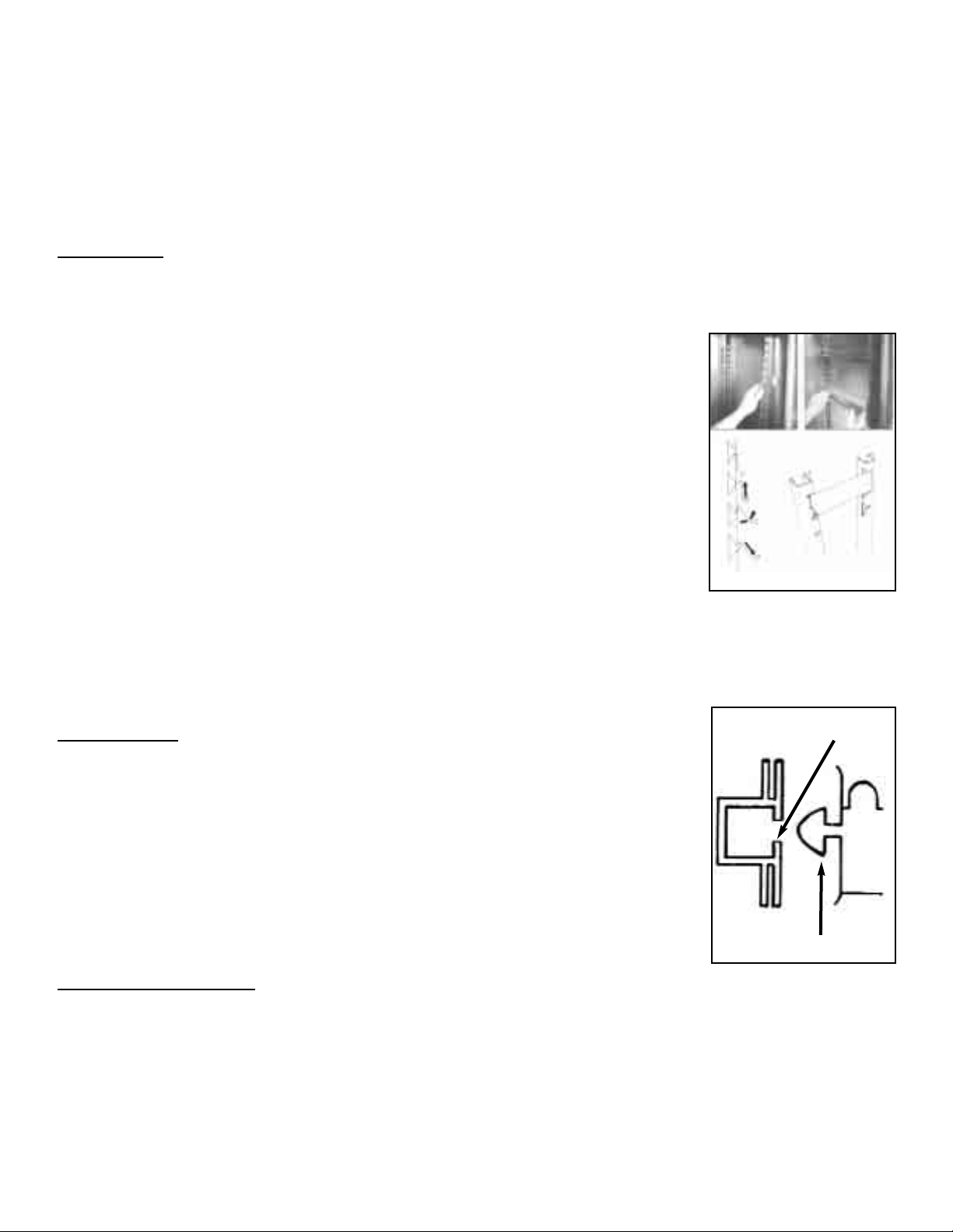
Interior: The racking can be removed for easy cleaning (see Fig 1). This
should be done on a regular basis with warm water and a soft cloth, dry
thoroughly afterwards. To remove the racking and shelf supports follow this
procedure: First remove the shelves, then remove the shelf supports by
grasping firmly in the center and lifting slightly. Turn the shelf support towards
the interior of the cabinet by pushing it in the center as you twist the support
through 90°. The shelf support will be released. (Note: the supports are
designed to be anti-tilt and you may therefore experience some resistance at
first which will be overcome with practice). When all shelves have been
removed, remove the racking by lifting up and over the nylon retaining blocks.
Door Gasket
Clean the gasket weekly with warm soapy water and a soft cloth taking care
not to damage it. DO NOT use a sharp knife to clean or scrape the gasket.
Regularly check the gasket for any damage. Damage can be caused by
striking the gasket with a sharp object such as the corner of a tray. Damaged
gaskets do not seal correctly and can increase the amount of electricity
consumed, seriously affecting the efficiency and performance of the cabinet.
Damaged gaskets are easily replaced. To fit a new gasket - simply pull out the
old gasket and push the new gasket into the channel (gasket retainer) at the
center and work along the gasket pushing it into the channel, continue in the
same way on the other three sides, pushing the corners in last (see Fig 2).
Condenser Cleaning
The condenser, which is part of the refrigeration unit, is sited in the unit compartment and requires
cleaning, approximately 4 times per year or when the LED indicates. To clean the condenser,
disconnect main power supply before starting, then brush the fins vertically with a stiff brush,
taking care not to damage the fins or push dirt or dust further in and vacuum away. Remember to
reconnect main power supply once finished.
Fig 1
Fig 2
Gasket
Retainer Channel
Page 13

9
TECHNICAL SERVICE & REPLACEMENT PARTS
Victory Refrigeration strives to provide excellent customer service along with quality equipment. To
help us better assist you, a serial number and/or model number must be provided when contacting the
technical service or parts department. The data plate is located inside the reach-in cabinet on the right
side wall. Roll-in blast chiller data plates are placed on the exterior of the back panel that supports the
controller. All serial numbers are recorded and kept indefinitely.
RULES OF THUMB
❒❒
Pre-chill the cabinet for thirty (30) minutes before you do first load (to remove interior residual heat).
❒❒
Doubling the food thickness triples the pull-down time.
❒❒
Don’t stack food and/or containers on top or alongside of each other.
❒❒
Covering the food increases pull-down time by 10% - 30%.
❒❒
Pull-down rate initially is about 2°F per minute and approaching final temperature is about 2
minutes per degree Fahrenheit.
❒❒
Factors affecting blast chill pull-down times:
1. Entering food temperatures (the hotter the initial temperature, the longer the pull-down time).
2. Final food temperature (the colder the final temperature, the longer the pull-down time).
3. Food “thickness” (the greater the distance from geometric “core” center of food to it’s surface
pull-down time).
4. Food density (the greater the density, the longer the pull-down time).
5. Food thermal conductivity (the lower the conductivity, the longer the pull-down time).
6. Food specific heats (the higher the specific heat, the longer the pull-down time).
7. Container surface area (the smaller the surface area, the longer the pull-down time).
8. Container material (metals are conductors and render a shorter pull-down than plastics which
are insulators).
9. Covering material (metal preferred instead of plastic for reasons above).
10. Covering method-cover such as aluminum foil or a “stretch wrap film” placed in direct
contact with food eliminates the “dead air space” between the cover and the food. Since
“dead air space” is an insulator, elimination of reduction of it shortens pull-down time.
11. “Delta T” is temperature difference between the food and the blast of air. The greater the
“Delta T” the quicker the pull-down time.
12. Air velocity (the greater the air velocity across the food, the faster the pull-down time).
13. Amount (weight) of food put in as compared to rated capacity of machine. Exceeding the
capacity increases the pull-down time.
14. Mechanical problems (equipment not operating at full efficiency takes longer to pull down)
Page 14

10
Page 15

11
VBC PARTS LISTS
Page 16

12
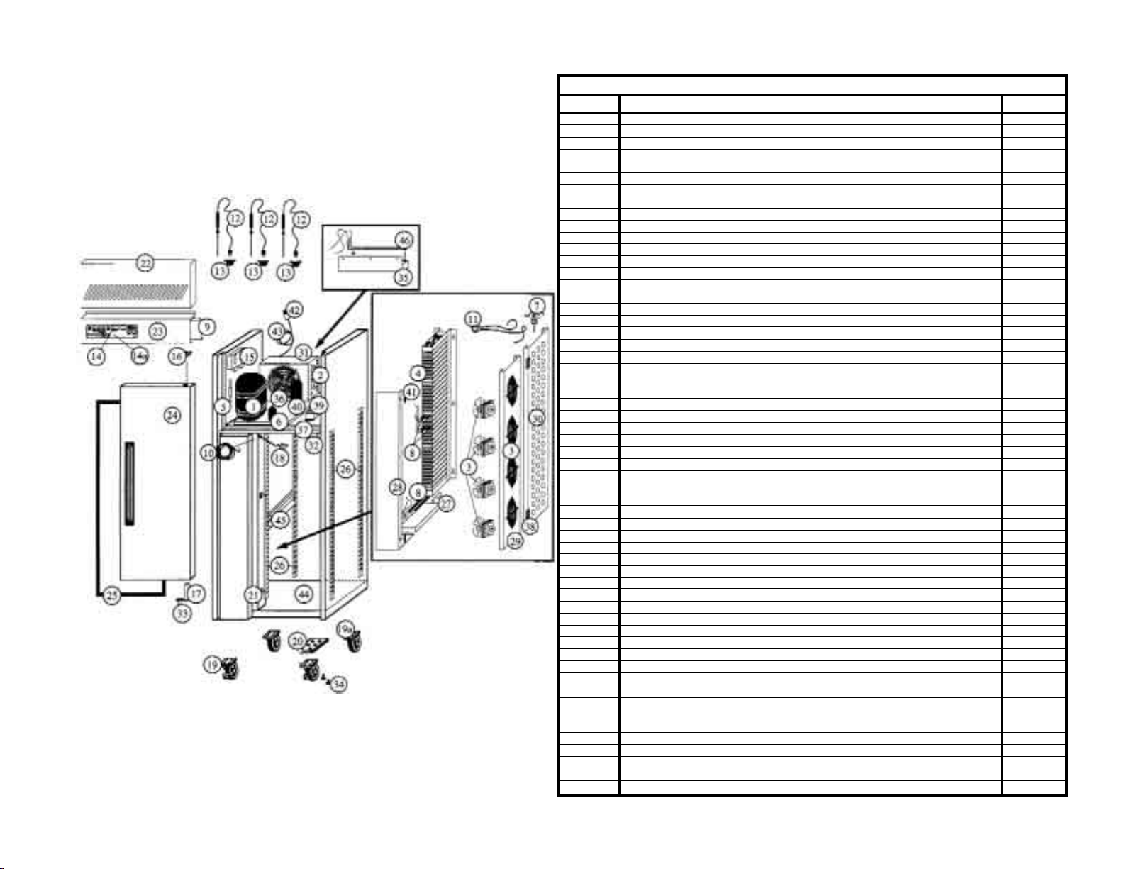
PARTS LIST FOR VICTORY BLAST CHILLER 35 (VBC-35)
Item No Description Part No.
1 Comp CAJ 4492Y R134A 52000101
1a Coil Condenser 3 x 11 x 21 52000201
1b Drier 1/4 x 3/16 Sweat R134A 52000301
1c Sight Glass 1/4 Sweat 52000401
2 Receiver 2.2L 52000501
3 Valve Expansion Body Ten 2 R134A 52000601
3 Valve Adapter Solder 1/4 52000701
3 Orifice No. 00 068-2090 52000801
4 Motor Condenser Fan 16 Watt 52000901
4 Blade Cond Fan 10In 27Dg Pitch 52001001
5 Plate Condenser Fan 52001101
6 Motor Evap Fan 315mm Axial 52001201
7 Guard Evap Fan Wire 50mm Deep 52001301
8 Plate Evaporator Fan 52001401
9 Upright Pilaster Racking 52001501
10 Probe Food 90 Degree Heavy Duty 52001603
10a Probe Socket Type T Flanged 52001701
11 Cover Unit Front Top Section 52001801
11a Cover Unit Front Bottom Section 52001901
12 Gasket Door 26-3/4 x 16-15/16 52002001
13 Plate Hinge R7 Opal Top 52002101
14 Hinge Door Spring Loaded 52002201
15 Door Standard VBC35 52002301
16 Coil Evaporator 4 x 13 x 17 52002401
17 Tray Drip 52002501
18 Heater Defrost 300W 3 Bend 52002601
19 Plug Nylon Door Hinge Top 52002701
20 Insert Nylon Pilaster Ladderack 52002801
21 Screw 6mm x 12 Pozi Pan Zinc 52002901
22 Label Polypanel W/O Printer 52003001
23 Panel Front No Printer 1Probe (123) 52003101
23 Board Back WBC II (123) 52003201
23 Logger Chip Full WBC II 52003301
23 Cable Ribbon Front To Back 1M 52003401
24 Leg, S/S 4IN Short Stud C/C Plate 52003501
25 Contactor 190V 50Hz/220V 60Hz 52003601
26 Screw 6mm x 25mm Zinc Pozi Pan 52003701
27 Slide Pan (Tray) S/S 276mm 52003801
28 Clip Latch Unit Cover Front 52003901
29 Clip Strike Unit Cover Front 52004001
30 Screw Set 8mm x 20mm Zinc 52004101
31 Cover Rear 52004201
32 Vaporizer Hot Gas 52004301
33 Plug 15 Amp 3 Pin 52004401
34 Cord Power Cable 3 Wire 14AWG 52004501
35 Insert Nylon Plstr Mtg Ladderack 52004601
36 Hinge Cabinet Piece 52004701
* Klixon 14T31 30210 L13C 9651 52004801
* Switch Thermal Heated 331-528 52004901
* Heater Wire 3M 240V 30 Watts 52005001
* Bracket Fan Motor 52005101
* Caster W/O Brake 52005201
* Caster W/ Brake 52005301
Page 17

13
PARTS LIST FOR VICTORY BLAST CHILLER 70 (VBC-70)
Item No Description Part No.
1 CONDENSING UNIT CAJ 4511Y HR 52077901
2 EVAPORATOR FAN 16 WATT 208V 60Hz UL 52078001
3 DEFROST HEATER 300W 1BEND 52078101
4 EVAPORATOR 3" x 20" x 20" 52078201
5 EXPANSION VALVE BODY TEN2 R134A 52000601
5 3/8" SOLDER ADAPTOR 068-2060 52010901
5 ORIFICE NO.2 068-2096 52071701
6 KLIXON 14T31 30210 L13C 9651 52004801
7 GASKET, 22" x 24" [560mm X 622mm] 52078301
7a PLUG, TOP HINGE 52078401
8 HINGE:SPRING LOADED 52002201
8a SCREW 8 X 1/2 POZI PAN ZINC S/T 52078501
8b HINGE PLATE:R4 FLAT 52078601
8c HINGE PLATE:R7 CHROME 52078701
9 CASTERS:NEW 6" UNBRAKED 52005201
9a CASTERS:NEW 6" BRAKED 52011701
9b SCREW M6 X 25 POZI PAN ZINC T/T 52003701
0 AARDWARE FRONT PANEL C/W PRINTER 3 PROBE 52011401
10 AARDWARE BACKBOARD (*ATTACHED BEHIND FRONT PANEL) 52003201
10 MAIN CONTROL BOARD WITH CONTACTORS 52044601
10 LOGGER CHIP FULL (*180 VERSION 11) 52003301
11 DRIER 3/8", R134a 52010801
12 LABEL,BLAST CHILLER 3 PROBE WITH PRINTER 52011501
13 90° ANGLED FOOD PROBE 52001603
14 SWITCH THERMAL HEATED 331-528 52004901
15 SIGHT GLASS, 3/8" SWEAT 52010701
16 LP SWITCH, TYPE G60 T01 52078801
16 HP SWITCH, TYPE G63 T01 52078901
17 1/4" SCHRAEDER VALVE 52079001
18 PLUG 3 PIN USA 15 AMP 52004401
18a CABLE FOR USA LEAD 3 CORE 14AWG/2MM 52004501
19 VAPORIZER HEATER, 115W 3 BEND 52014301
19 VAPORIZER HEATER, 150W 3 BEND 52014302
20 LADDERACK BLOCKS TYPE 1 52079101
20a LADDERACK BLOCKS TYPE 2 52002801
21 EVAPORATOR FAN PLATE 52079201
22 DRIP TRAY 52079301
23 VAPORIZER TRAY 52079401
24 DOOR ASSEMBLY, COMPLETE 52079501
25 UNIT COVER 52079601
26 RACKING, LEFT OR RIGHT SIDE 52079701
Page 18
14
PARTS LIST FOR VICTORY BLAST CHILLER 75 (VBC-75)
Item No Description Part No.
1 Comp 1-1/2 FH4518Y 208/60 52020101
2 Coil Condenser 4 x 17 x 17.5 52010201
3 Motor Evap Fan (4) 200mm Axial 52010301
3 Guard Evap Fan Flat 52010401
3 Capacitor 230V 60Hz 1.5UF 52020201
4 Coil Evaporator 5 x 45 x 16 52020301
5 Sight Glass 3/8 Sweat 52010701
6 Drier 3/8 Suitable For R134A 52010801
7 Valve Expansion Body Tes 2 R134A 52020401
7 Adapter Solder 3/8 068-2060 52010901
7 Valve Orifice No. 3 52011001
8 Heater Defrost 500W 1 Bend 52020501
9 Panel Control Cover Rear 52020601
10 Heater Wire 4.35 M 240V (57W) 52011301
11 Thermostat, Klixon 52004801
12 Probe Food 90 Degree Heavy Duty 52001603
13 Probe Socket Type T Flanged 52001701
14 Panel Front C/W Printer (123) 52011401
14 Board Back WBC II 52003201
14 Logger Chip Full 52003301
14 Cable Ribbon Front To Back IM 52003401
14a Polypanel W/ Printer 52011501
15 Control Pressure High/Low 52011601
16 Nylon Plug Door Hinge (Top) 52002701
17 Hinge, Spring Loaded Door 52002201
18 Switch, Thermal Heated 331-528 52004901
19 Caster 6" W/ Brake 52011701
19a Caster 6" W/O Brake 52011801
20 Plate Hinge L3 Opal/T2U Bottom 52011901
21 Insert Nylon Pilaster Ladderack 52002801
22 Cover Unit 52020701
23 Panel Control 52020801
24 Door Standard VBC75 52020901
25 Gasket 53-5/16 x 24-11/16 52021001
26 Upright Pilaster Ladderack 52021101
27 Tray Drip 52021201
28 Plate Baffle 52021301
29 Plate Evaporator Fan 52021401
30 Plate Evaporator Baffle 52021501
31 Plate Condenser Fan 52012901
32 Insert Door M4/T38 6x26 52013001
33 Screw M6x25 Pozi Countersunk 52013101
34 Screw 6mm x 25mm Zinc Pozi Pan 52003701
35 Vaporizer, Electric 52013201
36 Motor Condenser Fan 120 Watt 52013301
36 Capacitor 230V 60Hz 3.0UF 52013401
37 Panel Control Bottom 52013501
38 Cover Hinge Black Plastic 52013601
39 Contactor 190V 50Hz/220V 60Hz 52013701
40 Receiver 2.2L 52000501
41 Insert Nylon 316-F2/St38 M5X5 52013801
42 Cowl Condenser Fan 52021701
43 Slide Pan (Tray) 52021801
44 Control Panel Rear Cover 52021901
45 Thermocouple Type 'T' PTFE 2M 52022001
46 Vaporizer Heater 115W 3 Bend 52014301
46 Box Elec For Comp 833 TFH4524Z 52022101
Page 19

15
PARTS LIST FOR VICTORY BLAST CHILLER 100 (VBC-100)
Item No Description Part No.
1 Comp 2HP TFH 4524 Z 208/60/3 52020101
2 Coil Condenser 4 x 17 x 17.5 52010201
3 Motor Evap Fan (4) 200mm Axial 52010301
3 Guard Evap Fan Flat 52010401
3 Capacitor 230V 60Hz 1.5UF 52020201
4 Coil Evaporator 5 x 45 x 16 52020301
5 Sight Glass 3/8 Sweat 52010701
6 Drier 3/8 Suitable For R134A 52010801
7 Valve Expansion Body Tes 2 R404A 52020401
7 Solder Adapter 3/8 068-2060 52010901
7 Orifice No. 3 52011001
8 Heater Defrost 500W 1 Bend 52020501
9 Shelf Garnet White Coated 52020601
10 Heater Wire 4.35 M 240V (57W) 52011301
11 Thermostat, Klixon 52004801
12 Probe Food 90 Degree Heavy Duty 52001603
13 Probe Socket Type T Flanged 52001701
14 Front Panel C/W Printer (123) 52011401
14 Board Back WBC II 52003201
14 Logger Chip Full 52003301
14 Cable Ribbon Front To Back IM 52003401
14a Polypanel W/ Printer 52011501
15 Control Pressure High/Low 52011601
16 Nylon Plug Door Hinge (Top) 52002701
17 Hinge, Spring Loaded Door 52002201
18 Switch, Thermal Heated 331-528 52004901
19 Caster 6" W/ Brake 52011701
19a Caster 6" W/O Brake 52011801
20 Plate Hinge L3 Opal/T2U Bottom 52011901
21 Insert Nylon Pilaster Ladderack 52002801
22 Cover Unit 52020701
23 Panel Control 52020801
24 Door Standard VBC75 52020901
25 Gasket 53-5/16 x 24-11/16 52021001
26 Upright Pilaster Ladderack 52021101
27 Tray Drip 52021201
28 Plate Baffle 52021301
29 Plate Evaporator Fan 52021401
30 Baffle Plate Evaporator 52021501
31 Plate Condenser Fan 52012901
32 Insert Door M4/T38 6x26 52013001
33 Screw M6x25 Pozi Countersunk 52013101
34 Screw 6mm x 25mm Zinc Pozi Pan 52003701
35 Vaporizer Electric 52013201
36 Motor Condenser Fan 120 Watt 52013301
36 Capacitor 230V 60Hz 3.0UF 52013401
37 Panel Control Bottom 52021601
38 Cover Hinge Black Plastic 52013601
39 Contactor 190V 50Hz/220V 60Hz 52013701
40 Receiver 3.3L 52021701
41 Nylon Insert 316-F2/St38 M5X5 52013801
42 Cowl Condenser Fan 52021801
43 Slide Pan (Tray) 52021901
44 Panel Control Cover Rear 52022001
45 Thermocouple Type 'T' PTFE 2M 52022101
46 Box Elec For Comp 833 TFH4524Z52001241 52022201
46 Vaporizer Heater 115W 3 Bend 52014301
Page 20
16
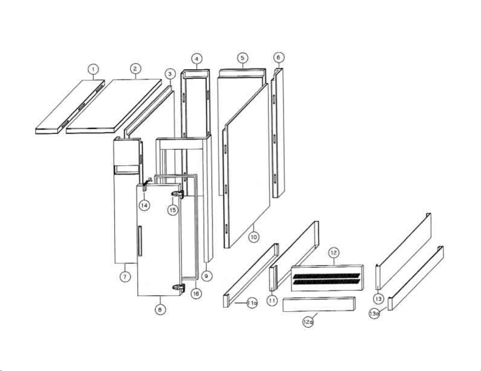
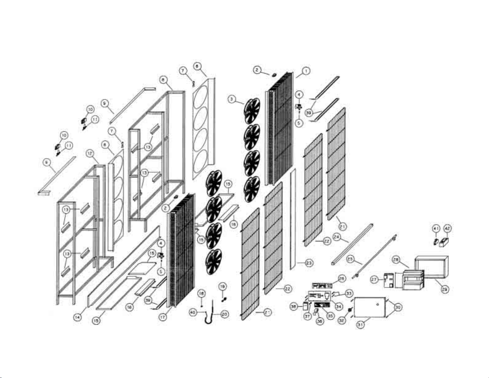
Victory Blast Chillers 175, 220 & 350 (VBC-175, VBC-220 & VBC-350) Panels Parts
Page 21
VBC-175, VBC-220 & VBC-350 Panels Parts List
Item # Part Description VBC-175 VBC-220 VBC-350
1 Panel Roof, Left 52040101 52040101 52040101
2 Panel Roof, Right 52040201 52040201 52040201
3 Panel Wall, Left Side 52040301 52040301 52040301
4 Panel Corner, Left Rear 52040401 52040401 52040401
5 Panel Wall, Rear 52040501 52040501 52040501
6 Panel, Coved Corner Right Rear 52040601 52040601 52040601
7 Panel Corner, Front Left 52040701 52040701 52040701
8 Door 52040801 52040801 52040801
9 Jam Corner, Coved 52040901 52040901 52040901
10 Panel Wall, Right Side 52041001 52041001 52041001
11 Upper End Panel (for Cabinet with “POD” Refrigeration System) 52041101 52041101 52041101
11a Upper End Panel (for Cabinet without “POD” Refrigeration System) 52041102 52041102 52041102
12 Grille, Front (for Cabinet with “POD” Refrigeration System) 52041201 52041201 52041201
12a Grille, Front (for Cabinet without “POD” Refrigeration System) 52041202 52041202 52041202
13 Upper End Panel (for Cabinet with “POD” Refrigeration System) 52041101 52041101 52041101
13a Upper End Panel (for Cabinet without “POD” Refrigeration System) 52041102 52041102 52041102
14 Latch, Door 52041301 52041301 52041301
15 Hinge, Door 52041401 52041401 52041401
16 Gasket, Door 52041501 52041501 52041501
17
18
Page 22

Victory Blast Chillers 175, 220 & 350 (VBC-175, VBC-220 & VBC-350) Equipment Parts
Page 23

19
VBC-175, VBC-220 & VBC-350 Equipment Parts List
Item # Part Description VBC-175 VBC-220 VBC-350
1 Bracket, Fan Guard 52041601 52041601 52041601
2 Plate, Fan 52041701 52050101 52060101
3 Angle, Roof 52041801 52041801 52041801
4 Valve, Solenoid EVR10 52041901 52041901 52041901
5 Valve, Coil Solenoid 60Hz 52042001 52042001 52042001
6 Blast Fans, HCGT-355J-MXNC 52042101 52042101 52042101
7 Switch, Fan Cut-Off ZC-055 52042201 52042201 52042201
8 Bracket, Frame Support 52042301 52042301 52042301
9 Frame, WBC R/H 52042401 52042401 52042401
10 Valve, Expansion (Power) 52042501 52042501 52042501
Valve, Expansion (Body) 52042601 52042601 52042601
11 Valve, Expansion Orifice 52042701 52050201 52060201
12 Coil, Evaporator (Dimensions: 6” x 66” x 19.5”) 52042801 52042801 52042801
13 Assembly, Drip Tray 52042901 52042901 52042901
14 Baffle, Drip Tray 52043001 50243001 52043001
15 Guard, Evaporator 52043101 52043101 52043101
16 Guard, Fan 52043201 52043201 52043201
17 Probe, 90 Degree Heavy Duty Food 52001603 52001603 52001603
18 Panel, Front C/W Print (123) 52011401 52011401 52011401
19 Board, WBC II Back 52003201 52003201 52003201
20 Screw, Control Panel 52043301 52043301 52043301
21 Fascia, Control Panel 52043401 52043401 52043401
22 Polypanel with Printer 52011501 52011501 52011501
23 Logger Paper 52043501 52043501 52043501
24 Cover, Printer 52043601 52043601 52043601
25 Latch 52043701 52043701 52043701
Striker 52043801 52043801 52043801
26 Switch, Isolator 52043901 52043901 52043901
Bar, Isolator 52044001 52044001 52044001
Handle, Isolator 52044101 52044101 52044101
27 Lid, Control Panel 52044201 52044201 52044201
28 Screw, Control Panel Lid 52044301 52044301 52044301
29 Contactor, Main Control Panel 52044401 52044401 52044401
30 Box, Control 52044501 52044501 52044501
31 Bumper, Cart Side 52044601 52044601 52044601
32 Bumper, Equipment Side 52044701 52044701 52044701
33 Plate, Bottom Blanking 52044801 52044801 52044801
34 Hinge, Fan Plate 52044901 52044901 52044901
35 Heater, Defrost (300 Watt, 1 Bend) 52045001 52045001 52045001
36 Grommet, Support 52045101 52045101 52045101
37 Grommet, Blind 52045201 52045201 52045201
38 Contactor, Cap and Bushing 52045301 52045301 52045301
39 Breaker, 30 Amp 2-Pole Circuit 52045401 52045401 52045401
40 Enclosure, 30 Amp 2-Pole Breaker 52045501 52045501 52045501
Page 24

20
Victory Blast Chillers 175, 220 & 350 (VBC-175, VBC-220 & VBC-350) Storage “POD” Parts
Page 25
VBC-175, VBC-220 & VBC-350 Storage “POD” Parts List
Item # Part Description VBC-175 VBC-220 VBC-350
1 Tray, Vaporizer 52045601 52045601 52045601
2 Heater, Vaporizer Tray 52045701 52045701 52045701
2a Klixon, Vaporizer Heater Tray 52045801 52045801 52045801
3 Unit, Condensing (Model: CAJ4461Y, 60Hz, R-134a) 52045901 52045901 52045901
4 Coil, Evaporator (Dimensions: 4” x 9” x 10”) 52046001 52046001 52046001
5 Valve, Expansion (Body) Ten 2 R-134a 52000601 52000601 52000601
Orifice, No. 1 68.2091 52046101 52046101 52046101
6 Chute, Air 52046201 52046201 52046201
7 Tray, “POD” Evaporator Drip 52046301 52046301 52046301
8 Motor, “POD” Fan 52046401 52046401 52046401
9 Plate, Fan 52046501 52046501 52046501
10 Bolt, M8 x 65 52046601 52046601 52046601
11 Lid, “POD” 52046701 52046701 52046701
12 Gasket, Tape Foam 52046801 52046801 52046801
13 “POD” 52046901 52046901 52046901
14 Liner, “POD” 52047001 52047001 52047001
15 Bushing, Bellmouth 52047101 52047101 52047101
21
Page 26

22
Victory Blast Chillers 480 & 660 (VBC-480 & VBC-660) Panels Parts
Page 27

VBC-480 & VBC-660 Panels Parts List
Item # Part Description VBC-480 VBC-660
1 Panel Roof, Left 52070101 52070101
2 Panel Roof, Right 52070201 52070201
3 Panel Wall, Left Side 52040301 52040301
4 Panel Wall, Left Side 52070301 52070301
5 Panel Corner, Left Rear 52040401 52040401
6 Panel Wall, Rear 52040501 52040501
7 Panel, Coved Corner Right Rear 52040601 52040601
8 Door 52040801 52040801
9 Jam Corner, Coved 52040901 52040901
10 Panel Wall, Right Side 52041001 52041001
11 Panel Wall, Right Side 52070401 52070401
12 Panel Corner, Front Left 52040701 52040701
13 Upper End Panel (for Cabinet with “POD” Refrigeration System) 52070501 52070501
13a Upper End Panel (for Cabinet without “POD” Refrigeration System) 52070502 52070502
14 Grille, Front (for Cabinet with “POD” Refrigeration System) 52041201 52041201
14a Grille, Front (for Cabinet without “POD” Refrigeration System) 52041202 52041202
15 Upper End Panel (for Cabinet with “POD” Refrigeration System) 52070501 52070501
15a Upper End Panel (for Cabinet without “POD” Refrigeration System) 52070502 52070502
16 Latch, Door 52041301 52041301
17 Hinge, Door 52041401 52041401
18 Gasket, Door 52041501 52041501
23
Page 28
24
Victory Blast Chillers 480 & 660 (VBC-480 & VBC-660) Equipment Parts
Page 29

25
VBC-480 & VBC-660 Equipment Parts List
Item # Part Description VBC-480 VBC-660
1 Coil, Evaporator (Dimensions: 6” x 66” x 19.5”) 52042802 52042802
2 Switch, Fan Cut-Off ZC-055 52042201 52042201
3 Fan, Blast HCGT-355J-MXNC 52042101 52042101
4 Valve, Expansion (Power) 52042501 52042501
Valve, Expansion (Body) 52042601 52042601
5 Valve, Expansion Orifice 52042701 52050201
6 Plate, Fan 52050101 52060101
7 Hinge, Fan Plate 52044901 52044901
8 Frame, WBC L/H 52042402 52042402
9 Angle, Roof 52070601 52070601
10 Valve, Coil Solenoid 60Hz 52042001 52042001
11 Valve, Solenoid EVR10 52041901 52041901
12 Frame, WBC L/H 52042401 52042401
13 Bracket, Frame Support 52042301 52042301
14 Plate, Bottom Blanking 52070701 52070701
15 Assembly, Drip Tray 52042901 52042901
16 Baffle, Drip Tray 52043001 52043001
17 Coil, Evaporator (Dimensions: 6” x 66” x 19.5”) 52042801 50242801
18 Grommet, Blind 52045201 52045201
19 Contactor, Cap and Bushing 52045301 52045301
20 Probe, 90 Degree Heavy Duty Food 52001603 52001603
21 Guard, Evaporator 52043101 52043101
22 Guard, Fan 52043201 52043201
23 Bracket, Fan Guard 52070801 52070801
24 Bumper, Equipment Side 52070901 52070901
25 Bumper, Cart Side 52071001 52071001
26 Panel, Front C/W Print (123) 52011402 52011402
27 Board, WBC II Back 52003202 52003202
28 Contactor, Main Control Panel 52071101 52071101
29 Box, Control 52071201 52071201
30 Screw, Control Panel Lid 52044301 52044301
31 Lid, Control Panel 52071301 52071301
32 Switch, Isolator 52043901 52043901
Bar, Isolator 52044001 52044001
Handle, Isolator 52044101 52044101
33 Screw, Control Panel 52043301 52043301
34 Fascia, Control Panel 52071401 52071401
35 Polypanel with Printer 52011502 52011502
36 Logger Paper 52043501 52043501
37 Latch 52043701 52043701
Striker 52043801 52043801
38 Cover, Printer 52071501 52071501
39 Heater, Defrost (300 Watt, 1 Bend) 52045001 52045001
40 Grommet, Support 52045101 52045101
41 Breaker, 30 Amp 2-Pole 52045401 52045401
42 Enclosure, 30 Amp 2-Pole Breaker 52045501 52045501
Page 30

26
Victory Blast Chillers 480 & 660 (VBC-480 & VBC-660) Storage “POD” Parts
Page 31

VBC-480 & VBC-660 Storage “POD” Parts List
Item # Part Description VBC-480 VBC-660
1 Tray, “POD” Evaporator Drip 52071501 52071501
2 Coil, Evaporator (Dimensions: 4” x 10” x 22”) 52071601 52071601
3 Valve, Expansion 068Z3385 52000601 52000601
Orifice No. 1 68.2092 52071701 52071701
4 Motor, “POD” Fan 52046401 52046401
5 Plate, Fan 52071801 52071801
6 Unit, Condensing (Model: CAJ4492YHR, 60Hz, R-134a) 52071901 52071901
Drier, 3/8” Sweat 52072001 52072001
7 Heater, Vaporizer Tray (300 Watt, 3 Bend) 52072101 52072101
8 Klixon, Tray Heater 52045801 52045801
9 Tray, Vaporizer 52072201 52072201
10 Bolt, M8 x 65 52046601 52046601
11 Lid, “POD” 52072301 52072301
12 Gasket, Tape Foam 52046801 52046801
13 “POD” 52072401 52072401
14 Liner, “POD” 52072501 52072501
15 Chute, Flush 2 Fan Air 52072601 52072601
27
Page 32
28
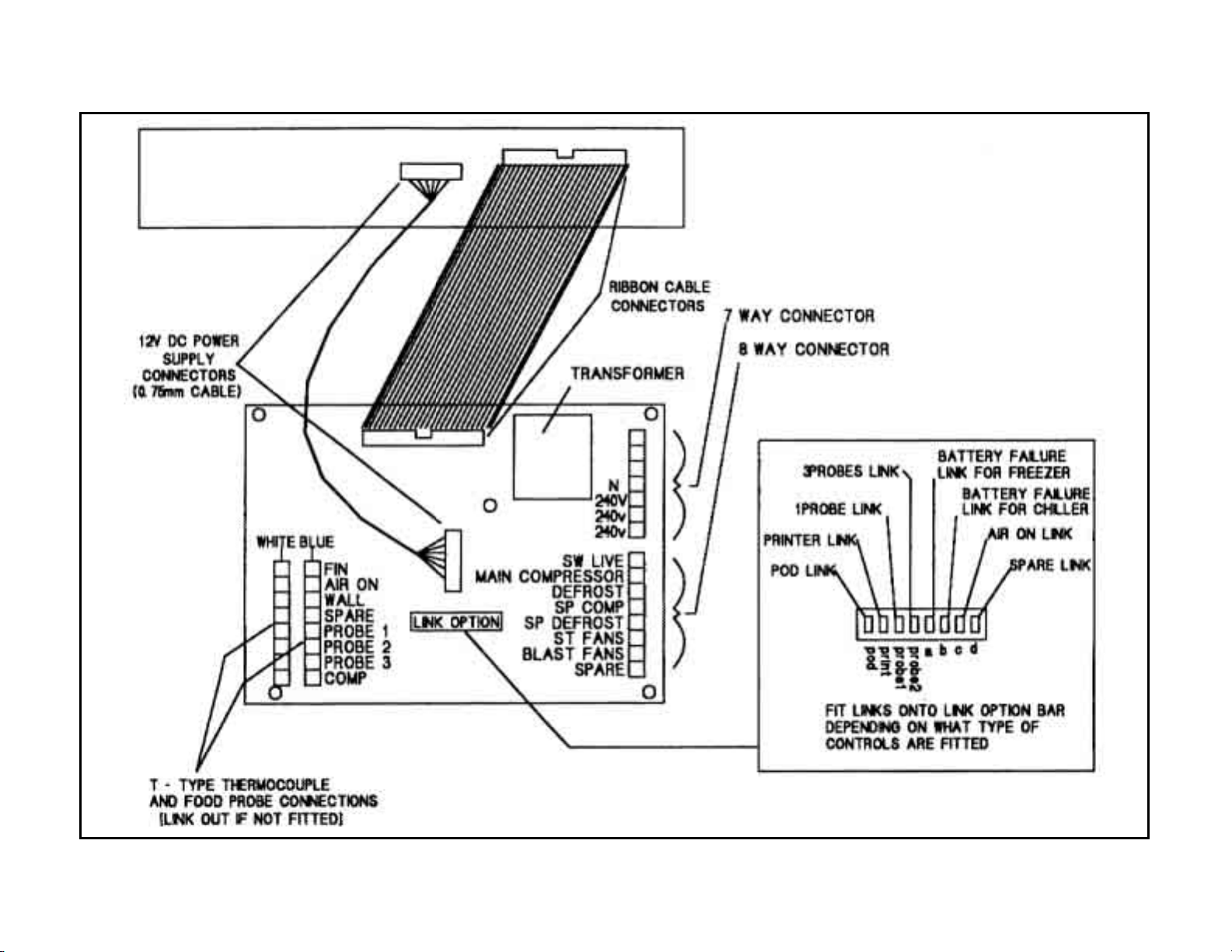
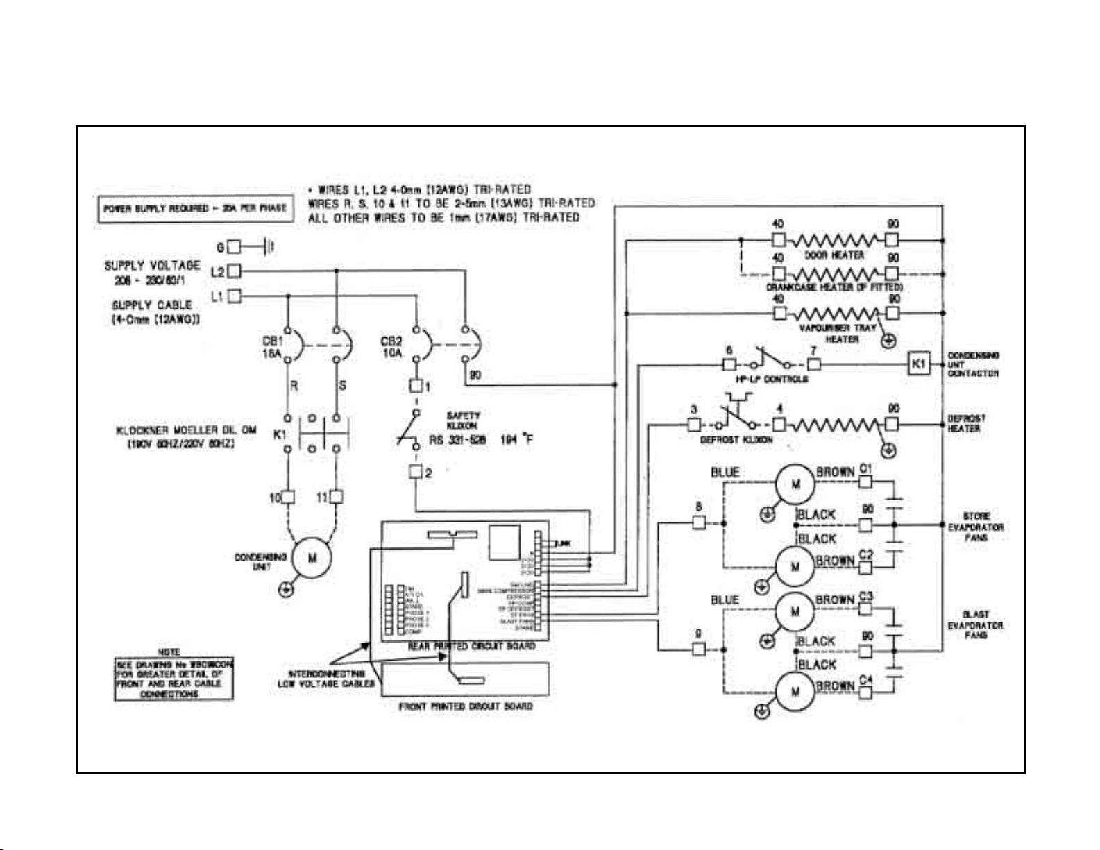
CABLE CONNECTIONS & THERMOCOUPLES
Page 33

29
VBC-35 (208-230V/60Hz/1Ph)
Page 34

30
VBC-70 (208-230V/60Hz/1Ph)
Page 35
31
VBC-75 (208-230V/60Hz/1Ph)
Page 36

32
VBC-100 (208-230V/60Hz/3Ph)
Page 37

33
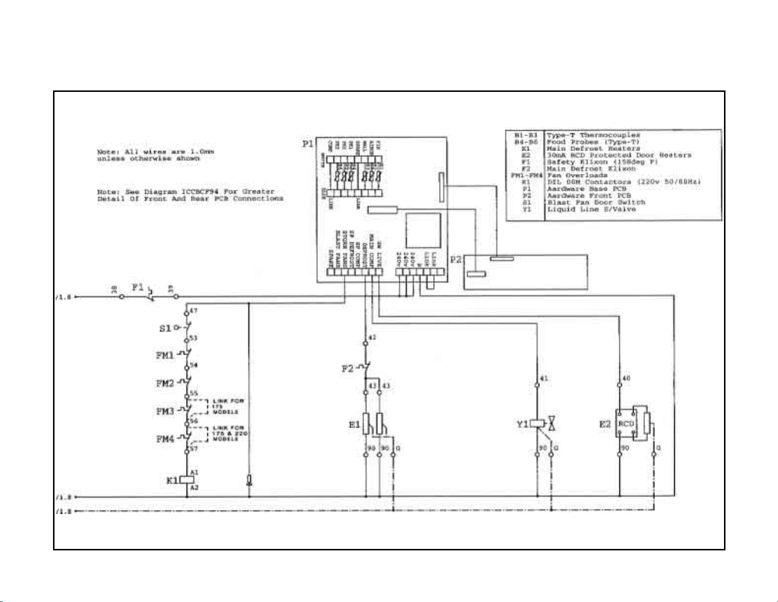
VBC-175, 220 & 350 with “POD” Refrigeration System
(208-230V/60Hz/3Ph), Page 1of 2
Page 38

34
VBC-175, 220 & 350 with “POD” Refrigeration System
(208-230V/60Hz/3Ph), Page 2 of 2
Page 39

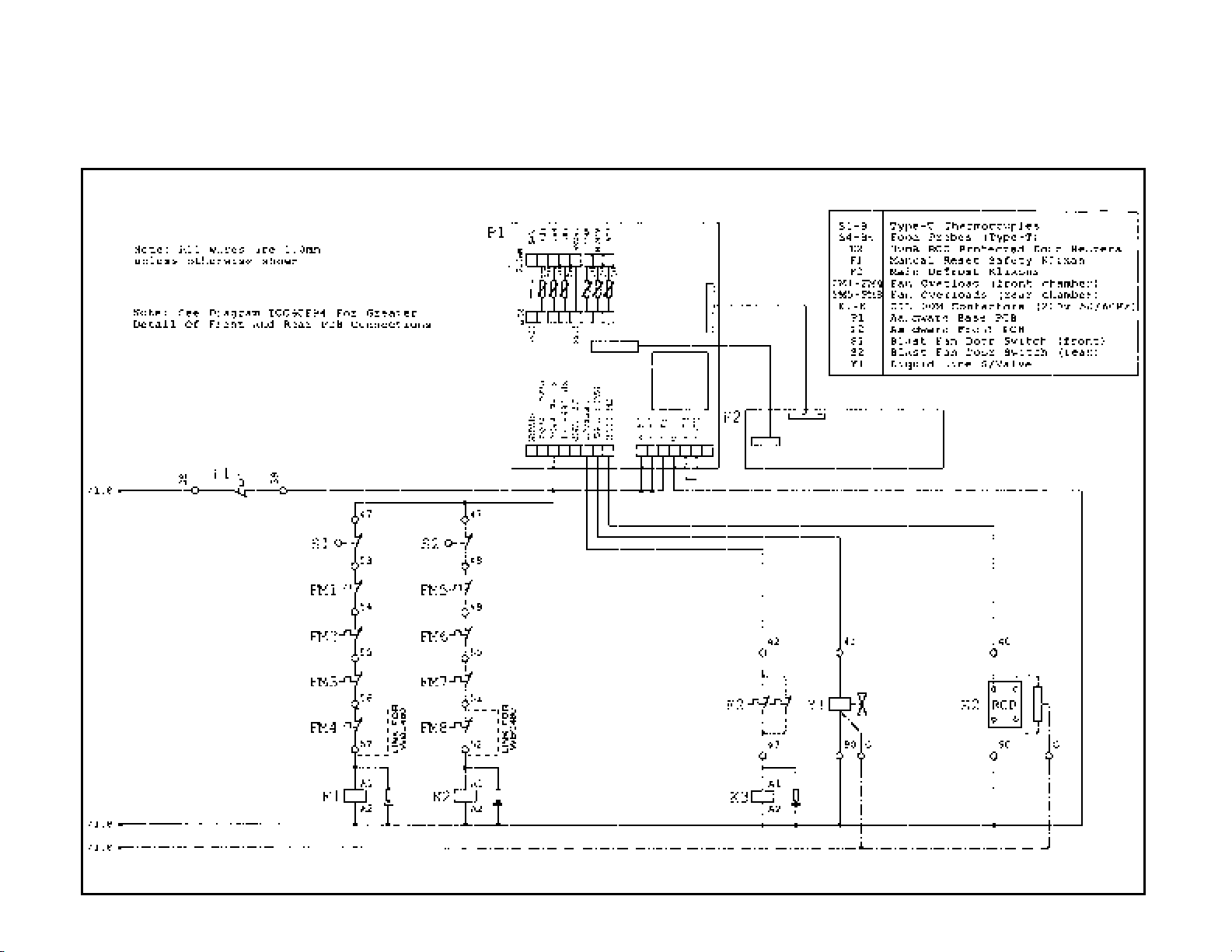
VBC-175, 220 & 350 without “POD” Refrigeration System
(208-230V/60Hz/3Ph), Page 1 of 2
35
Page 40
VBC-175, 220 & 350 without “POD” Refrigeration System
(208-230V/60Hz/3Ph), Page 2 of 2
36
Page 41

VBC-480 & 660 with “POD” Refrigeration System
(208-230V/60Hz/3Ph), Page 1 of 2
37
Page 42

VBC-480 & 660 with “POD” Refrigeration System
(208-230V/60Hz/3Ph), Page 2 of 2
38
Page 43

VBC-480 & 660 without “POD” Refrigeration System
(208-230V/60Hz/3Ph), Page 1 of 2
39
Page 44
VBC-480 & 660 without “POD” Refrigeration System
(208-230V/60Hz/3Ph), Page 2 of 2
40
Page 45

Page 46

Victory Refrigeration Inc
110 Woodcrest Road
Cherry Hill, NJ 08003-3648
Tel: (856) 428-4200
Fax: (856) 428-7299
Web: www.victory-refrig.com
E-mail: service@ victory-refrig.com
or
parts@victory-refrig.com
 Loading...