

Page 1

1 | P a g e
User Guide
VICTORY VX100 ‘The Super Kraken’
All Valve 100-Watt MIDI Guitar Head
Page 2

2 | P a g e
Thank you, and congratulations on acquiring a Victory Amplification VX100. This amp is proudly designed
and built by our committed team of engineers and craftsmen in the UK.
We value simplicity in operation, flexibility in use and absolutely no compromise in tone. Our aim is
simple: to create amplifiers that inspire you ever onwards in your playing and never let you down.
SAFETY FIRST
We want you to enjoy your amplifier to the best of its potential. So please…
Before you go any further, take a moment to read these SAFETY INSTRUCTIONS
• Read these guidelines & keep them
• Follow all instructions & guidelines
• Do not use this amplifier near water or any other liquid
• Do not block any openings
• Do not attempt to clean the amplifier with any fluids: use only a dry cloth
•
Do not attempt to modify or service this product yourself
•
Removing covers could mean you are exposed to dangerous voltages that may result in severe injury or
death
• Refer all servicing to qualified service personnel
• It is the nature of valve amplifiers to get hot, so please take care when moving the amp after use.
• Damage Requiring Service: Unplug this product from the wall outlet and refer servicing to qualified
service personnel under the following conditions:
(a) When the power-supply cord or plug is damaged;
(b) If liquid has been spilled, or objects have fallen into the product;
(c) If the product has been exposed to rain or water;
(d) If the product does not operate normally by following the operating instructions. Adjust only those
controls that are covered by the operating instructions. Improper adjustment of other controls may
result in damage and will often require extensive work by a qualified technician to restore the product
to its normal operation;
(e) If the product has been dropped or damaged in any way;
(f) When the product exhibits a distinct change in performance - this indicates a need for service.
•
Replacement Parts: When replacement parts are required, be sure the service technician uses
replacement parts specified by the manufacturer or have the same characteristics as the original part.
Unauthorized substitutions may result in fire, electric shock, or other hazards.
What’s included?
Your new Victory VX100 comes with the following:
1 x Dual Latching Footswitch for GAIN I/II and MASTER I/II
1 x Dual Latching Footswitch for Preamp Bass Focus and Crunch
A mains lead for your country
A dust cover.
This User Guide (please check the website periodically as these owner’s manuals are constantly
being updated to give you more information about your Victory product). The issue number can
be found on the last page.
Page 3

3 | P a g e
FRONT PANEL
INPUT Jack
Plug your guitar in here!
FX LOOP SWITCH
This switch is to manually switch the Effects Loop ON/OFF. To control this via MIDI, the switch needs to
be in the centre or ‘Null’ position. This function is also footswitchable using an optional 2-way latching
footswitch. These are available from the Victory Store.
In the ON position, this switch will override the latching footswitch or MIDI Footcontroller.
PREAMP FOCUS SWITCH
This switch is used to manually switch the Preamp Bass Focus ON/OFF. This function enhances the midrange frequencies before the first gain stage. To control this via MIDI, the switch needs to be in the
centre or ‘Null’ position. This function is also footswitchable using the supplied 2-way latching
footswitch. In the ON position, this switch will override the latching footswitch or MIDI Footcontroller.
CLEAN/CRUNCH SWITCH
This switch is used to change the mode of GAIN I between CLEAN and CRUNCH. To control this via MIDI,
the switch needs to be in the centre or ‘Null’ position. This function is also footswitchable using the
supplied 2-way latching footswitch. In the ON position, this switch will override the latching footswitch
or MIDI Footcontroller.
GAIN I
When switched to ‘CLEAN’ this control will progressively add a small amount of gain to the guitar signal
but will allow for a high-headroom clean sounds When switched to CRUNCH the GAIN I adds a classic
British crunch to the sound. Use carefully when you want to introduce more natural valve overdrive to
your tone.
Balancing this control with either Master Volumes is crucial in delivering the tone and feel that works
best for you.
GAIN I/II SWITCH
Switches between the two different Gain ranges. To control this via MIDI, the switch needs to be in the
centre or ‘Null’ position. This function is also footswitchable using the supplied 2-way latching
footswitch. In the ON position, this switch will override the latching footswitch or MIDI Footcontroller.
GAIN II
This control adds more of a modern American high-gain character to the content of your sound and
again should be used in conjunction with both Master controls to achieve the tonal response you desire.
BASS
This controls the low frequency content of your sound. Higher levels of bass can be good at low volumes,
but take care when running the amp louder – you may find you need to reduce the bass control. As with
all the EQ pots, adjust to taste!
Page 4

4 | P a g e
MIDDLE
Controls the midrange frequencies in your sound. Run the middle control higher to help cut through a
band mix, or generally fatten and ‘widen’ your sound. Run it lower for a lighter, less ‘in-your-face’ kind
of sound.
TREBLE
Controls the high frequency content of your sound and is also a powerful tone shaper when it comes to
overdrive character.
MASTER I
The Master I Volume control is used to set the stage or overall volume of the VX100. If this is turned to
maximum, then the VX100 becomes a non-master volume amplifier where either Gain control in
conjunction with the Volume control on the guitar allows for a wide range of Volumes & Gains to be
achieved. This can be very powerful for tone shaping.
The Master Volume control is positioned before the phase splitter valve and after the FX return.
MASTER II
The Master II Volume control performs the exact same function as Master I but allows you to set
different Volume levels and when used in conjunction with the footswitchable Gain settings, allows for
instant switching for solo boost. Master II is only activated when the supplied 2-way Footswitch is used.
MASTER I/II SWITCH
Switches between MASTER I and MASTER II. To control this via MIDI, the switch needs to be in the
centre or ‘Null’ position. This function is also footswitchable using the supplied 2-way latching
footswitch. In the ON position, this switch will override the latching footswitch or MIDI Footcontroller.
Power Lamp with Purple Jewel
When lit, this indicates that mains power has been applied to the amplifier. It houses a 6.3V 10mm
bayonet filament bulb which can be replaced by unscrewing the jewel from the front.
HIGH – PREHEAT – LOW Switch.
The VX100 should always be switched on, (mains switch on rear of amplifier), with this front panel
toggle switch in its centre position. The amplifier is now in ‘PREHEAT’ mode with just the valve heaters
and low voltages on. This allows the valves to heat up before they get 100s of volts up them, (it’s less of
a shock). After around 60 seconds, the amp can be switch to either HIGH, (around 100 Watts rms) or
LOW, (around 30 Watts rms). Due to recent EU regulations on the use of ‘Standby’ functions and their
associated low-power requirements, we have replaced the function with PREHEAT to avoid any legal
confusion. There will be no difference in operation of the amplifier. When switching the amplifier ON or
OFF please ensure the Volumes are turned down and you leave at least 30 seconds before switching
from PREHEAT to Off. This will ensure extended valve life and avoid any power-down noise. This is
especially relevant if you’re running through a large PA system as any small pop may become amplified
to audience death levels, which may limit your music career.
REAR PANEL
Page 5

5 | P a g e
Voltage Selector
This selects the correct mains voltage for your territory. Please refer to a qualified technician before
even thinking about moving this switch. If you do find yourself in foreign climes where the mains voltage
is different to home, (and the water tastes funny), it will be necessary to switch this selector. The mains
fuse must always be changed at the same time. Failure to do this will result in either the mains fuse
blowing as soon as the amp is turned on or the amp running with a fuse that is of too higher value to
provide adequate safety protection. Generally, the fuse value will double if the mains voltage is halved,
(i.e. if it’s a 3.15A fuse in the UK @ 230V, it will need to be a 6.3A fuse for the USA @ 115V).
Always use the correct rating and type of fuse. Victory amplifiers exclusively use UL-approved 20x5mm
glass ‘T’ or ‘Timed’ fuses. If you have difficulty acquiring the correct fuses, please contact Victory using
Mains Inlet, (IEC Socket)
Please only use the correct mains cord for your territory!
Mains Power Switch.
The mains switch turns your amplifier ‘ON’. Ensure the front panel toggle switch is in the middle,
‘PREHEAT’ position before turning on the mains.
HT FUSE
The HT or ‘High Tension’ fuse protects the high voltage for the valve supply. If this fuse blows, the first
step is to replace it with an identical T1A 20x5mm fuse. The HT fuse may sometimes blow due to ‘flashover’ inside an output valve. This is where during the valve manufacturing process, not all of the gas is
removed from the glass envelope and the ‘getter’ inside the valve, usually made from barium or
magnesium oxide, will burn or evaporate these remaining gasses resulting in the common silvered
internal surface of the valve. This process, which is more likely to happen with new equipment in the
first 50 hours of use, draws high current momentarily and can blow the HT fuse. It will rarely cause any
damage so just replacing the fuse is sufficient to get the amp running normally again.
However, if the HT FUSE consistently blows, it may indicate a serious valve failure where internal parts
of a valve are shorted and in this case the amplifier needs to be checked by a qualified engineer to assess
the problem.
VERY IMPORTANT WARNINGS!!
In certain countries, (specifically, Nordic countries), is it totally forbidden to open up any electronic
equipment or to work on them at all unless you are a fully qualified and approved technician. Please
check the laws in your country and do not attempt to change valves/tubes or re-bias the amplifier if the
law forbids this. In this case, please take your amplifier to a qualified and approved electronics
technician.
In certain countries it is also totally forbidden to keep or place any liquids on top of the amplifier, (e.g.
beer, water bottles, glass, drinks etc). This may cause serious electric shocks and/or dangerous
situations.
Also, it is totally forbidden to use the amp in the event of rain splatters/water drops getting into or onto
the amp.
Even if it is not a law in your country, you should never allow liquids near the amplifier or attempt to use
the amplifier if it has been subjected to any moisture as this could result in a fatal electric shock.
BIAS ADJUST
Biasing needs to be done each time the output valves are replaced and should be checked periodically to
make sure they are working at their optimum for sound quality & valve life.
Firstly, there is a small chrome toggle switch on the top of the chassis just above the Bias section which
sets the voltage range for a choice of output valves. The rear grill needs to be removed to gain access to
Page 6

6 | P a g e
this switch. For EL34s, this should be switched away from the output valves, (to the left when viewed
from the rear) and for 6L6s, it should be set towards the output valves, (to the right when viewed from
the rear).
To set the Bias on the VX100 you need a multimeter set to the 200mV DC range. Biasing is carried out
externally so no need to remove the amp from the wooden sleeve. Output valves can be replaced from
the rear of the amp by simply removing the back grill and carefully pushing down on the sides of the
retaining butterfly clips. We recommend the use of a soft cloth to remove valves if possible. The valves
can then be pulled out using a slow rotational movement, (dweezling) to ease them from their sockets.
This will free them with the least amount of effort and stress. Ensure that the key on the replacement
valves lines up with the keyway on the socket before carefully pushing them home. Take care when
removing any valve as the pins can easily be bent and the plastic locating key on the output valves can
be snapped off. Make sure that they are never more than a few degrees from vertical to avoid bending
or breaking pins etc.
Always try to buy a matched Quad set of output valves or at the very least, 2 matched pairs or Biasing
may be difficult if not impossible. The closer the output valves are matched, the longer they are likely to
last as they will all be drawing a similar current and some won’t be working harder than others.
To Bias the new valves, make sure the amplifier is connected to a speaker cabinet, (or dummy load
resistor), of the correct impedance that matches with the speaker output being used. Turn all controls to
zero and remove the guitar input as any signals may interfere with the Bias settings. Switch the rear
power switch to ON with the front panel switch in the PREHEAT position. Wait 60 seconds and then
switch the front panel switch to HIGH.
Now put the black meter probe, (-ve) into the Black centre GND Bias socket and the red meter probe,
(+ve) into the left hand V5+ & V6+ Bias socket. Using a small flat blade screwdriver in the Bias
adjustment POT, turn this so you get 34mV on the multimeter. This equates to 34mA of current per valve
as we are measuring the voltage across a 1 Ohm resistor.
Now put the red meter probe into the right hand V7+ & V8+ Bias socket and measure the voltage. Try to
balance the 2 measurements around 34mV with a maximum of 6mV between them. For example, an
extreme but perfectly acceptable case would be 31mV for V5 & V6 and 37mV for V7 & V8.
All Victory amplifiers are constructed using Posidrive Screws & Machine Bolts. These are an
improvement on the Phillips type of fixing which uses a 4-blade screwdriver. The Posidrive uses an 8Blade screwdriver which allows for more precision and higher torque. Please try to use Posidrive
Screwdrivers when working on a Victory amplifier. These are readily available from all good tool
suppliers. We recommend having a No.1 and a No.2 point Posidrive screwdriver.
Speaker Outputs
PLEASE NOTE: The lightning flash with arrowhead symbol, within an equilateral triangle, is intended to
alert the user to the presence of uninsulated ‘dangerous voltage’ within the product’s enclosure that
may be of sufficient magnitude to constitute a risk of electric shock. Terminals labelled as “Speaker
Outputs” must be connected to a speaker cabinet of the designated load rating using an un-shielded two
conductor cable for speaker use at all times during operation. Never use a guitar cable to connect the
amplifier to a speaker as this presents the amplifier with a ‘capacitive load’. A screened guitar cable is
effectively 2 conductors with an insulator between them which is the same construction as a capacitor.
This can cause instability or oscillation which may seriously damage valves and/or the expensive output
transformer.
Always ensure a speaker is connected to the amplifier before powering up or damage to the output
transformer may result. Never unplug a speaker when the amplifier is ON as this is even more likely to
damage the transformer and the output valves.
Page 7

7 | P a g e
The output transformer in the VX100 has 3 separate secondary windings; a 16 Ohm, an 8 Ohm and a 4
Ohm. This makes it easy to connect many different combinations of speakers. There are five speaker
output jacks: 1 x 16 ohms, 2 x 8 ohms, (wired in parallel), 2 x 4 ohms, (wired in parallel).
So here are all the possible combinations:
1. For a single 4 Ohm cabinet, use either of the 4 Ohm sockets.
2. For a single 8 Ohm cabinet, use either of the 8 Ohm sockets.
3. For a single 16 Ohm cabinet, use the 16 Ohm socket, (internal speaker).
4. For a pair of 8 Ohm cabinets, use both of the 4 Ohm sockets
5. For a pair of 16 Ohm cabinets, use both of the 8 Ohm sockets.
Always ensure a speaker is connected to the amplifier before powering up or damage to the output
transformer may result. Never unplug a speaker when the amplifier is ON as this is even more likely to
damage the transformer and the output valves.
POWER AMP BASS FOCUS SWITCH
This function alters the negative feedback at low frequencies in the poweramp resulting in a ‘looser’ or
‘tighter’ overall bass response. This will be affected by the positions of the tone controls so please
experiment with this switch to achieve the bass response you desire.
MIDI Section
The switchable functions of VX100 can be activated using a standard MIDI controller. All of the
combinations of functions can be found in the table below. There are 24 separate MIDI Presets; for
example, Preset 3 will switch GAIN I/II to GAIN II, MASTER I/II to MASTER I, PREAMP FOCUS to OFF and
EFFECTS LOOP to ON. Any function labelled N/A in the table will not be available for that particular
Preset. For example, in Preset 3, CLEAN/CRUNCH is not applicable because the amp will be switched to
Gain II where that function is not available.
PRESET
NUMBER
GAIN I/II
MASTER I/II
CLEAN/CRUNCH
PREAMP FOCUS
EFFECTS LOOP
1 I I
CLEAN
OFF
ON
2 I I
CRUNCH
OFF
ON
3
II I N/A
OFF
ON
4 I II
CLEAN
OFF
ON
5 I II
CRUNCH
OFF
ON
6
II
II
N/A
OFF
ON
7 I I
CLEAN
ON
ON
8 I I
CRUNCH
ON
ON
9
II I N/A
ON
ON
10 I II
CLEAN
ON
ON
11 I II
CRUNCH
ON
ON
12
II
II
N/A
ON
ON
13 I I
CLEAN
OFF
OFF
14 I I
CRUNCH
OFF
OFF
15
II I N/A
OFF
OFF
16 I II
CLEAN
OFF
OFF
17 I II
CRUNCH
OFF
OFF
18
II
II
N/A
OFF
OFF
Page 8
8 | P a g e
19 I I
CLEAN
ON
OFF
20 I I
CRUNCH
ON
OFF
21
II I N/A
ON
OFF
22 I II
CLEAN
ON
OFF
23 I II
CRUNCH
ON
OFF
24
II
II
N/A
ON
OFF
To get the MIDI working you will need a suitable MIDI Footcontroller. Connect this to the 5-PIN MIDI DIN
socket on the rear of the VX100 using a standard 5-PIN DIN cable.
Now we need to ensure that the VX100 is set to the same MIDI Channel as the MIDI Footcontroller. The
instructions that came with the MIDI controller will state which channel it is set to.
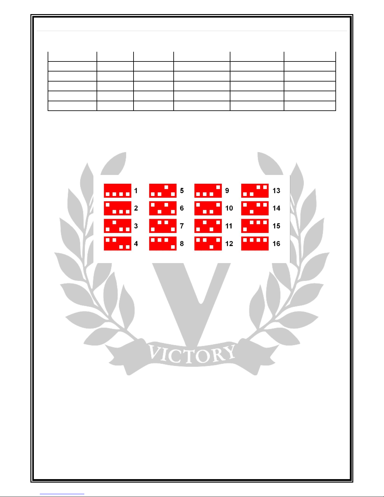
The following table shows the 16 possible channels that the VX100 can be set to, using the 4-PIN DIP
switch found next to the footswitch sockets, (labelled MIDI CHANNEL):
For example, if your MIDI controller is set to channel 4, then from the table above, the DIP switches on
the VX100 should be set with the first 2 up and the second 2 down.
Now turn the amplifier ON and check MIDI operation ensuring all mini front panel toggle switches are in
the centre, (NULL) position. For example, press Preset 5 and the amplifier should now be set to GAIN I,
MASTER II, CRUNCH, PREAMP FOCUS OFF and EFFECTS LOOP ON.
It is possible to alter the combination of presets out of the 24 available. To do this switch the MIDI
Footcontroller to your chosen Preset and then switch the front panel toggle switches ‘ON’ or ‘OFF’ for
your desired choice of function. Once you have done this, press the MIDI STORE button above the MIDI
DIP Switches. Now set all mini front panel toggle switches to the NULL centre position. Now when this
Preset is selected on the MIDI Footcontroller, the functions you have selected, (STORED) will be recalled.
The MIDI Reset button, accessible via a small hole next to the MIDI Store button, will reset the MIDI
Presets back to the original Fatory settings as found in the table at the beginning of this section.
Notes on operation:
To avoid any conflicting behavior, please do not use a MIDI Footcontroller in conjunction with the
latching footswitches.
FOOTSWITCH SECTION
FOOTSWITCH 1: Preamp Bass Focus, (Tip of TRS Jack) & Clean/Crunch, (Ring of TRS Jack).
Connect the supplied Dual latching footswitch here to switch the Preamp Bass Focus ON/OFF and
between Clean/Crunch for GAIN I.
FOOTSWITCH 2: GAIN I/II (Tip of TRS Jack) & MASTER I/II (Ring of TRS Jack)
Connect the supplied Dual latching footswitch here to switch between GAIN I & II and between MASTER
VOLUMEs I & II.
Page 9

9 | P a g e
FOOTSWITCH 3: MASTER I/II + GAIN I/II (SOLO OVERRIDE - Tip of TRS Jack) & FX LOOP ON/OFF (Ring of
TRS Jack)
Connect an optional Dual latching footswitch here, (available from your Victory dealer and the Victory
Store), to switch the GAIN & MASTER at the same time. When activated, this will switch to GAIN II and
MASTER II independent of previous GAIN & MASTER VOLUME settings. If used without Footswitch 1
plugged in and the GAIN switch in position I then the amplifier acts as a 2-Channel system. With both
Footswitches inserted then the front panel GAIN I/II switch is overridden. The second button will switch
the FX LOOP ON/OFF. For the SOLO Override to function, the switches for GAIN I/II and MASTER I/II
need to be in the centre or ‘Null’ position.
EFFECTS LOOP
The VX100 has an effects loop, which is a simple, low impedance, series loop.
The SEND socket is for connection to the input of effects units. On the VX100 it is a lower impedance
version of the signal that appears at the INPUT. Use the SEND to connect to floor pedals or rack effects
such as Delay, Chorus and Reverb etc. Effects such as Overdrive, Fuzz, Wah Wah and Tuners often give
better results plugged into the Instrument Input on the front panel. The SEND socket can also be used on
its own to send a signal to another amplifier.
The RETURN socket is for connection to the output of effects units. When not used it is internally
connected to the SEND, therefore the EFFECTS LOOP can be ignored if not in use. It can also be used as a
small signal ‘Slave’ input from another amplifier but DO NOT plug an amplifier’s speaker output into the
Return socket or very bad things will happen.
The RETURN socket is also very useful for fault diagnosis. If your VX100 doesn’t produce any sound when
played, plug the guitar directly into the RETURN socket and play. This bypasses the entire pre-amplifier
section and sends the guitar signal through just the output stage. If sound is now heard then the
problem is in the pre-amp section and is likely to be a faulty pre-amp valve.
Amplifier Dimensions:
SIZE (mm): 480(w) x 235(h) x 235(d) including handle & feet Unboxed.
590(w) x 350(h) x 350(d) Boxed.
Weight: 12.5Kgs, (27.5lbs) Unboxed. 16Kgs, (35.2lbs) Boxed
Output Power.
WARNING! The VX100 has been designed to achieve a very high sound pressure level (SPL) so caution is
required when playing in high power mode or hearing damage may result.
The following measurements were taken at 240V mains input into an 8 Ohm load using a 1 KHz Sine
Wave with the output waveforms set just before clipping. MASTER VOLUME I and GAIN I were used and
the tone controls set to give the best representation of a sine wave:
High Power: 110 Watts (we nominally rate the V130 at 100 Watts as not everyone is going to get 240V
from their mains supply, 230V is more common).
Low Power: 30 Watts
Valves: 4 x ECC83, (12AX7), 4 x 6L6 or EL34, (see notes in BIAS section for BIAS Toggle Switch).
Notes on output volume and speaker attenuation:
Victory amplifiers are designed to be played loud with gigging and rehearsal in mind. It can be quite
difficult to get suitable volumes and tones from the VX100 at home or ‘bedroom’ levels even in the
lower power settings. The nature of valve amps and the POTs used to control the signal are such that
they only really start to work when turned up. However, many Victory users have had great success with
speaker power-soaks and simulators. The simplest ones are low-cost attenuators such as the Jet City
‘Jettenuator’ which simply soaks up the output power of the amplifier allowing only some of the signal
Page 10

10 | P a g e
to reach your speaker(s). This allows you to really crank the amplifier up into output valve distortion to
get big-stage overdrive without disturbing anyone.
https://www.thomann.de/gb/jet_city_amplification_jettenuator.htm?glp=1&gclid=CKjxmLe-ktICFeqc7QodK6IInA
For home studio recording and speaker attenuation, at the top end of the market, we have the Two
Notes Torpedo range of attenuators & simulators. These are really excellent devices and are what our
colleague Rabea Massaad uses for home recording:
https://www.andertons.co.uk/search?query=torpedo
There are many others out there with Palmer being one of the first companies to offer such devices.
These are tried and tested solutions and also recommended by Victory:
https://www.andertons.co.uk/b/139/palmer
Warranty:
All Victory products come with a 5 year limited warranty. This covers any defects in manufacturing or
faulty components. Valves and speakers are warrantied for 90 days from the purchase date but
replacement parts will be at our discretion. Please contact your local dealer if you have any issues with
your Victory product. Victory are setting up Official Service Centres around the world so please check on
the Victory website to see where your nearest centre is located. These will have original Victory spare
parts including the recommended valves for your amplifier direct from the Victory factory. They also
have all technical details for your product and have been carefully selected to ensure you get the best
possible service for warranty and non-warranty work.
Notes on what to do if your amplifier experiences any strange behavior:
Dec 2018: over 6000 amplifiers have now been shipped out of the factory and from 5 years answering
service queries, the main issues that come up are valve-related. These are either premature valve
failure, (minimal), valves that have worn out through extended use or have become microphonic or
noisy over time.
Many issues relating to valves can be cured simply by re-tensioning the valve bases. Over time, the valve
sockets, which are constantly heating up, cooling down, expanding and contracting may become a bit
‘loose’ and not hold the valve pins as tight as they should. This can lead to noise and more commonly,
sudden drops in volume or complete lack of sound.
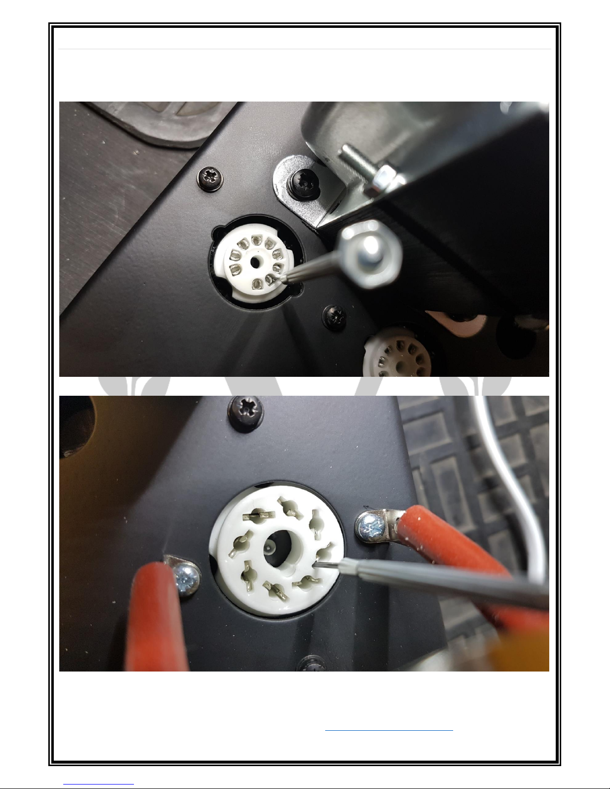
It is an easy task to re-tension the valve sockets and this can be done with a small flat blade screwdriver
such as this:
Carefully remove each valve in turn. The pre-amp valves have a sprung-loaded screening can fitted over
each one so turn this through 90 degrees or so until it pops off. Then using the slow circular motion, pull
the valve from the socket. The output valves are retained by spring clips which can just be slid off the
top of the valves.
Please ensure that the valves go back into the same sockets as they are optimized at the factory for best
position relating to gain, noise, & microphony. This is easily achieved if you just do one at a time; take it
out, re-tension then re-insert and go to the next one.
You will see that the valve bases have small 2-part metal clips in each hole and these need to be pushed
together to make a tight connection on the valve pins.
Page 11
11 | P a g e
Pre-amp valves:
Poweramp Valves:
Please make sure you don’t close these pins up fully or it will be difficult to replace the Valves.
Replacement valves and tools for biasing such as a Multimeter and Terminal Screwdrivers are available
directly from Victory. Please email your requirements to [email protected] for a quote.
Page 12

12 | P a g e
A note from Team Victory
We’ve built your Victory Amplifier as a professional, no-compromise musical instrument, with a great
deal of pride and an absolute commitment to tone. We encourage you to learn to get to know it by
experimenting with all the controls, in order to discover its vast array of tonal combinations.
Thank you for making your tones with us: we wish you many years of achieving inspiring sounds to push
your playing ever onwards.
Now we’ll shut up; you go play yer guitar.
Contact info:
Web: www.victoryamps.co.uk www.youtube.com/user/VictoryAmps
www.facebook.com/VictoryAmpsUK www.victorystore.co.uk
Handmade in England Issue 1 06.12.2018
 Loading...