


 Loading...
Reach-In & Pass-Thru Refrigerator and Freezer Models
Installation, Operation and Troubleshooting Manual
Manual Part No. 50707411
Rev. 00
Print Date: 04/12/12
11 0 Wo o d c r e s t R o a d , C h e r r y H i l l , N J 0 8 0 0 3
Phone: (856) 428-4200 Fax: (856) 673-0038 Website: www.victoryrefrigeration.com
E-Mail: parts@victoryrefrigeration.com order-entry@victoryrefrigeration.com service@victoryrefrigeration.com

T H A N K Y O U
Thank you for purchasing a Victory ULTRASPEC™ Series cabinet! This unit has passed our strict Quality Control Inspection and meets the high standards set by Victory Refrigeration. You have made a quality investment that with proper maintenance will give you many years of service.
Please read the following installation and maintenance instructions before installing or using your unit. If you have any questions, please call our Technical Service Department at (800) 523-5008.
IMPORTANT INFORMATION - PLEASE READ
*Please read these instructions carefully before installing or using. If recommended procedures are not followed, warranty claims may be denied.
*Your Warranty Registration information is located on the next page of this manual. Please complete the card and submit it to Victory Refrigeration within 10 days of installation. Failure to properly register equipment may limit or void the warranty.
*Victory Refrigeration reserves the right to change specifications and product design without notice. Such revisions do not entitle the buyer to corresponding changes, improvements, additions or replacements for previously purchased equipment.
LIMITED WARRANTY
(Continental USA Only)
The Seller warrants to the original purchaser, equipment manufactured by Seller to be free from defects in material and workmanship for which it is responsible. The Seller’s obligation under this warranty shall be limited to replacing or repairing at Seller’s option, without charge, F.O.B. Seller’s factory, any part found to be defective and any labor and material expense incurred by Seller in repairing or replacing such part, such warranty to be limited to a period of twelve (12) months from the date of installation, provided, however, installation occurs within three (3) months of date of purchase and equipment is in normal use and service and is installed in accordance with manufacturer’s recommendations and provided terms of payment have been fully met. All labor shall be performed during regular working hours. Overtime premium charges will be at Buyer’s expense.
Proof of purchase must be supplied to Seller to validate warranty. This warranty is valid only if equipment is properly installed, started-up and inspected by the dealer or authorized Victory Service agent.
Removal or alteration of the serial/data plate from any equipment shall be deemed to release Seller from all warranty obligations or any other obligations, expressed or implied.
This warranty does not cover Thermostat, Controller, Thermometer or Defrost Timer calibration and/or adjustment, freight damage, normal maintenance items outlined in Owner’s Manual, adjustment of door mechanisms or replacement of door gaskets, light bulbs, fuses or batteries. The warranty does not cover installation, start-up, normal maintenance, food loss, or other consequential damage.
Any repairs or replacement of defective parts shall be performed by Seller’s authorized service personnel. Seller shall not be responsible for any costs incurred if the work is performed by other than Seller’s authorized service personnel. Reimbursement claims for part(s) or labor service costs must be made in writing. Model, cabinet serial numbers and installation location must be shown on the claim. A receipted bill from the servicing agency must accompany the claim, together with full details of the service problems, diagnosis and work performed. Victory will determine at its sole discretion whether further documentation on a claim is to be submitted.
Seller shall not be liable for consequential damages of any kind which occur during the course of installation of equipment, or which result from the use or misuse by Buyer, its employees or others of the equipment supplied hereunder, and Buyer’s sole and exclusive remedy against Seller for any breach of the foregoing warranty or otherwise shall be for the repair or replacement of the equipment or parts thereof affected by such breach.
The foregoing warranty shall be valid and binding upon Seller if and only if Buyer loads, operates and maintains the equipment supplied hereunder in accordance with the instruction manual provided to Buyer. Seller does not guarantee the process of manufacture by Buyer or the quality of product to be produced by the equipment supplied hereunder and Seller shall not be liable for any prospective or lost product or profits of Buyer.
THE FOREGOING WARRANTY IS EXCLUSIVE AND IN LIEU OF ALL OTHER EXPRESS AND IMPLIED WARRANTIES WHATSOEVER. SPECIFICALLY THERE ARE NO IMPLIED WARRANTIES OF MERCHANTABILITY OR OF FITNESS FOR A PARTICULAR PURPOSE.
The foregoing shall be Seller’s sole and exclusive obligation and Buyer’s sole and exclusive remedy for any action, whether in breach of contract or negligence. In no event shall Seller be liable for a sum in excess of the purchase price of the item.
You may fax this completed page to (856) 673-0038, or copy and mail the form below to Victory.
NOTE: The mail-in or faxed form must be filled out and forwarded to Victory by the installer or customer within 10 days after start-up. Failure to do this may invalidate the warranties. Retain this information for your records.
|
|
|
110 WOODCREST ROAD |
|
Cabinet Model No. |
|
|
|||||||||
|
|
|
CHERRY HILL, NJ 08003-3648 |
|
|
|||||||||||
|
|
|
|
Cabinet Serial No. |
|
|
|
|||||||||
|
|
|
TEL: (856) 428-4200 : FAX: (856) 673-0038 |
|
|
|
||||||||||
|
|
|
|
|
||||||||||||
|
|
|
|
|
|
|
|
(Data plate information located inside cabinet on the upper left wall) |
||||||||
WARRANTIES NOT VALID UNLESS REGISTERED AT |
||||||||||||||||
|
|
|
|
|
|
|
|
|
||||||||
FACTORY WITHIN 10 DAYS AFTER START-UP DATE. |
|
|
|
|
|
|
|
|
|
|||||||
|
|
|
|
|
|
|
|
|
|
|
|
|
|
|
||
ORIGINAL DATE OF INSTALLATION |
|
|
|
|
|
|
|
|
|
|
|
|||||
CUSTOMER NAME |
|
|
|
|
|
PHONE |
|
|
|
|
|
|
||||
STREET |
|
|
|
CITY |
|
|
STATE |
|
|
ZIP CODE |
|
|||||
DEALER'S NAME |
|
|
|
|
|
|
PHONE |
|
|
|
|
|
|
|||
|
|
|
|
|
|
|
|
|
|
|
||||||
STREET |
|
|
CITY |
|
|
STATE |
|
|
|
ZIP CODE |
|
|||||
Glossary of Common Terms & Descriptions
C
Compressor - The compressor is the heart of the system. The compressor does just what it’s name states. It compresses the low pressure refrigerant vapor from the evaporator and compresses it into a high pressure vapor.
The inlet to the compressor is called the “Suction Line”. It brings the low pressure vapor into the compressor.
After the compressor compresses the refrigerant into a high pressure Vapor, it removes it to the outlet called the “Discharge Line”.
Condenser Coil - The “Discharge Line” leaves the compressor and runs to the inlet of the condenser coil located on top of the cabinet. Because the refrigerant is compressed, it is a hot high pressure vapor (as pressure goes up – temperature goes up). The hot vapor enters the condenser coil and starts to flow through the tubes. Cool air is blown across the outside of the finned tubes of the condenser coil (usually by a fan or water with a pump).
Since air is cooler than the refrigerant, heat jumps from the tubing to the cooler air (energy goes from hot to cold – “latent heat”). As the heat is removed from the refrigerant, it reaches it’s “saturated temperature” and starts to “flash” (change states), into a high pressure liquid.
The high pressure liquid leaves the condenser coil through the “liquid line” and travels to the “metering device”. Sometimes running through a
filter dryer first, to remove any dirt or foreign particles.
D
Defrost - The term is used to identify the function of a refrigerator or freezer to remove frost or ice from the internal evaporator coil.
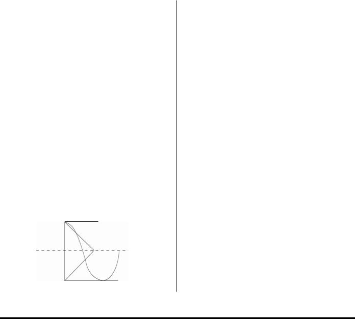
Differential - An increment in a given function, expressed as the product of the derivative of that function and the corresponding increment in the independent variable
An example of "differential" is below.
 Cut-In (36°F)
E
Energy Saving Mode - A mode automatically activated during periods when the kitchen is not operating. After four (4) hours of no door openings, the cabinet will revert to the energy saving mode.
F
FLEXTEMP Mode (*optional feature) - This option provides the ability to select a unique refrigerator temperture from 28°F to 40°F for multipurpose applications.
H
HACCP Functions - The V-TEMP™ controller records all critical temperature events including the date and time when the alarms occurred.
M
Manager's Lockout Feature - This feature prevents unauthorized employees from changing programmed settings on the control panel.
S
Setpoint - This is the refrigerator or freezer cut out temperature set by the operator. Prior to shipping, refrigerators are factory preset at 35°F and freezers are factory preset at -2°F.
SUPERCOOL Mode - When initiated, this feature provides a "constant on" refrigeration condition for when food has just been loaded into a refrigerator and needs to be quickly brought down to a safe temperature protecting costly food investment and extending product shelf life.
4°F Differential
Cut-Out (32°F)

Table of Contents |
|
RECEIVING, UNCRATING & INSTALLATION |
|
Receiving................................................................................................................................................................... |
1 |
Uncrating..................................................................................................................................................................................... |
1 |
Storage Refrigerator/Freezer Location....................................................................................................................... |
1 |
InstallingLegsorCasters............................................................................................................................................... |
1 |
Leveling............................................................................................................................................................................ |
2 |
CabinetCleaning............................................................................................................................................................ |
2 |
InstallingShelves.............................................................................................................................................................. |
2 |
ElectricSupply.................................................................................................................................................................. |
2 |
Controller.......................................................................................................................................................................... |
2 |
Installation Checklist.................................................................................................................................................. |
2 |
ProductLoad.............................................................................................................................................................. |
2 |
V-TEMP™ ELECTRONIC CONTROLLER |
|
LED Indicators & Alarms............................................................................................................................................. |
3 |
Keypad&AssociatedFunctions..................................................................................................................................... |
3-5 |
Alarm Codes, Descriptions & Resolution(s)................................................................................................................ |
5 |
ErrorCodes....................................................................................................................................................................... |
5 |
UserParameters............................................................................................................................................................ |
6-7 |
PERIODIC CLEANING |
|
Cabinet Cleaning....................................................................................................................................................... |
8 |
Condenser Maintenance............................................................................................................................................ |
8 |
Lubrication............................................................................................................................................................... |
9 |
Installing Replacement Door Gasket......................................................................................................................... |
9 |
TROUBLESHOOTING GUIDE FOR COMMON PROBLEMS |
|
Common Problems & Remedies............................................................................................................................. |
10 |
COMMON REPLACEMENT PARTS |
|
Refrigeration System Replacement Parts................................................................................................................. |
11 |
Controller Replacement Parts................................................................................................................................... |
11 |
Door Assembly Replacement Parts..................................................................................................................... |
11-12 |
Interior Light Assembly Replacement Parts............................................................................................................. |
12 |
WIRING DIAGRAMS |
|
1, 2 & 3 Section Refrigerator 115 Volt/15 Amp & 20 Amp......................................................................................... |
13 |
1, 2 & 3 Section Refrigerator 115 Volt/208-230 Volt Condensing Unit...................................................................... |
13 |
1, 2 & 3 Section Freezer 115 Volt/15 Amp & 20 Amp................................................................................................ |
14 |
1, 2 & 3 Section Freezer 115 Volt/208-230 Volt Condensing Unit............................................................................. |
14 |

RECEIVING, UNCRATING & INSTALLATION INSTRUCTIONS
Proper installation is the first step to operation. We recommend that your refrigerator or freezer be installed by a Victory authorized service technician.
Receiving
Prior to shipping, all Victory products are factory tested for performance and thoroughly inspected to ensure they are free of any defects. Upon receipt, carefully examine the unit for any damage that may have occurred during shipping and delivery. Any damage, discrepancies, shortages or overages should be noted on the carrier's Bill of Lading and a freight claim must be filed immediately with the carrier. If damage is noticed after receipt, contact the carrier's local terminal and file a freight claim. In either case, it is important that all original cartons, crates and interior packaging material are saved until inspection has been made with the delivering carrier.
Uncrating
WARNING: Never lay your refrigerator or freezer down on either its back, front or sides. This causes compressor oil to enter the refrigerant lines which can damage the compressor at start-up. If the unit is laid down, it must be set upright for a minimum of 24 hours before starting the compressor. Failure to adhere to the above recommendation will void the warranty.
Tools Needed : 3/4” Box Wrench, Adjustable Wrench, Level, Flathead Screwdriver, Box Cutting (or Carpenter) Knife
1.Take off the cardboard top capping by removing all clear tape and staples with a flathead screwdriver. Also remove all staples at the bottom of the cardboard carton and skid.
2.Starting from the top of the cardboard carton, carefully take a box cutting knife and try to make one continuous cut until you come to the wooden skid. Remove the cardboard carton from around the cabinet and discard.
*Note: An additional clear, plastic, protective wrap is applied directly to the exterior of all cabinets with glass doors.
3.Move cabinet as close to final location as possible before removing skid.
4.Remove the shipping skid by tipping the cabinet forward. Remove the shipping bolts with 3/4” box wrench while the cabinet is held in one direction. Repeat this procedure while the cabinet is held in the opposite direction.
WARNING: The cabinet must be blocked and secured when removing the shipping skid.
5.Remove protective vinyl coating from all interior and exterior surfaces.
Storage Refrigerator/Freezer Location
Consider the following when selecting a location for your refrigerator or freezer:
1.Clearance - There must be a minimum clearance of 12” between the top of the refrigerator or freezer and the ceiling.
2.Floor Load - The floor on which the cabinet will rest must be even/level, free of vibration and strong enough to support the combined weights of the cabinet plus the maximum product load.
3.Ventilation - The air cooled, self-contained refrigerator or freezer requires a sufficient amount of cool, clean air. Avoid placing the refrigerator or freezer near heat generating equipment such as ovens, ranges, heaters, fryers, steam kettles, etc., and out of direct sunlight. Avoid locating the self-contained refrigerator or freezer in an unheated room, or where the room temperature may be below 55°F.
Installing Legs or Casters
Refrigerators and freezers are shipped with 1/2” single stud mounted legs or casters.
WARNING: Cabinet must be blocked and secured when installing legs or casters.
1.Legs/Casters must be screwed in by hand into the threaded holes located on the case bottom. No threads of the leg or caster stem should be visible.
*NOTE: Once the caster cannot be turned, using a 3/4” box wrench, tighten the nut in between the mounting plate and wheel of the caster until it is snug.
2.Tilt the cabinet in one direction approximately eight inches and block it securely with several pieces of 2" x 4" lumber or other suitable material.
3.Screw in the two left or right legs/casters.
4.Repeat this procedure to install the other legs/casters.
1
Loading...