

Page 1

Page 2
Page 3
California Proposition 65 Warning
This product contains or emits
chemicals known to the state of
California to cause cancer and birth
defects or other reproductive harm.
inside cover.fm Page 202 Tuesday, April 1, 2008 9:45 AM
Page 4

1
INTRODUCTION
2009 VICTORY VISION RIDER’S MANUAL
Copyright2008 Polaris Sales Inc. All Rights Reserved.
P/N 9921967
Printed in U.S.A.
visionownersmanual.book Page 1 Wednesday, February 13, 2008 4:31 PM
Page 5

2
INTRODUCTION
General Information
All information contained within this publication is based on the latest product information
available at the time of publication. Product improvements or other changes may result in
differences between this manual and the motorcycle. Depictions and/or procedures in this
publication are intended for reference use only.
No liability can be accepted for omissions or inaccuracies. Polaris Industries reserves the
right to make changes at any time, without notice and without incurring obligation to make
the same or similar changes to motorcycles previously built. Any reprinting or reuse of the
depictions and/or procedures contained within, whether whole or in part, is expressly
prohibited.
All reference to RIGHT, LEFT, FRONT, REAR are from the operator’s perspective seated in a
normal riding position.
Features of VICTORY Motorcycles are covered by U.S. Patent Nos: 6,976,691; 6,407,663;
D489670; D482311; D482304; D481980; D481973; D474142.
visionownersmanual.book Page 2 Wednesday, February 13, 2008 4:31 PM
Page 6

3
INTRODUCTION
Trademarks
The following are registered trademarks of Polaris Industries Inc.
POLARIS
POLARIS THE WAY OUT
VICTORY
VICTORY MOTORCYCLES
VICTORY VISION
FREEDOM
DUNLOP is a registered trademark of Dunlop Tire Corporation.
LOCTITE is a trademark of Henkel Corporation.
XM and its corresponding logos are trademarks of XM Radio Inc.
iPod is a registered trademark of Apple Inc.
visionownersmanual.book Page 3 Wednesday, February 13, 2008 4:31 PM
Page 7
4
INTRODUCTION
Before You Ride
Read your Rider’s Manual
This Rider’s Manual contains information that is essential to safe riding and proper
maintenance of your VICTORY VISION motorcycle. Anyone who uses the motorcycle
(operators and passengers) must read the Rider’s Manual before riding. Carefully read and
understand the information found in the Safety section. Understand and follow the
procedures outlined in the Maintenance section to keep your VICTORY motorcycle in top
condition on the road or in storage. Bring the manual with you when you ride. Following the
precautions and procedures in the manual will add to your enjoyment and help keep you
riding safely. If you lose or damage this manual, you can purchase a new one through any
authorized VICTORY dealer. The Rider’s Manual should be considered part of the
motorcycle and remain with it if sold.
WARNING
Failure to follow the safety precautions and operation and maintenance procedures outlined
in this manual could result in death or injury (to you or your passenger) or damage to the
motorcycle.
visionownersmanual.book Page 4 Wednesday, February 13, 2008 4:31 PM
Page 8
5
TABLE OF CONTENTS
BEFORE YOU RIDE . . . . . . . . . . . . . . . . . . . . . . . . . . . . . . . . . . . . . . . 4
SAFETY . . . . . . . . . . . . . . . . . . . . . . . . . . . . . . . . . . . . . . . . . . . . . . 7-36
REPORTING SAFETY DEFECTS . . . . . . . . . . . . . . . . . . . . . . 35
IDENTIFICATION / COMPONENT LOCATION . . . . . . . . . . . . . . 37-46
INSTRUMENTS, FEATURES & CONTROLS . . . . . . . . . . . . . . . . 47-84
PRE-RIDE CHECKS . . . . . . . . . . . . . . . . . . . . . . . . . . . . . . . . . . 85-106
OPERATION . . . . . . . . . . . . . . . . . . . . . . . . . . . . . . . . . . . . . . . 107-128
MAINTENANCE . . . . . . . . . . . . . . . . . . . . . . . . . . . . . . . . . . . . . 129-206
CLEANING . . . . . . . . . . . . . . . . . . . . . . . . . . . . . . . . . . . . . . . . . 207-216
STORAGE . . . . . . . . . . . . . . . . . . . . . . . . . . . . . . . . . . . . . . . . . 217-224
WARRANTY . . . . . . . . . . . . . . . . . . . . . . . . . . . . . . . . . . . . . . . . 225-238
visionownersmanual.book Page 5 Wednesday, February 13, 2008 4:31 PM
Page 9

6
TABLE OF CONTENTS
SPECIFICATIONS . . . . . . . . . . . . . . . . . . . . . . . . . . . . . . . . . . . 239-250
AUDIO
SYSTEM OVERVIEW . . . . . . . . . . . . . . . . . . . . . . . . . . . 251-258
FEATURES . . . . . . . . . . . . . . . . . . . . . . . . . . . . . . . . . . . 259-276
CB RADIO - ICOM . . . . . . . . . . . . . . . . . . . . . . . . . . . . . . 277-292
AUX - iPod
. . . . . . . . . . . . . . . . . . . . . . . . . . . . . . . . . . . 293-298
XM RADIO . . . . . . . . . . . . . . . . . . . . . . . . . . . . . . . . . . . . 299-302
CD CHANGER . . . . . . . . . . . . . . . . . . . . . . . . . . . . . . . . . 303-306
INDEX. . . . . . . . . . . . . . . . . . . . . . . . . . . . . . . . . . . . . . . . . . . . . 307-320
visionownersmanual.book Page 6 Wednesday, February 13, 2008 4:31 PM
Page 10
7
SAFETY
Safety
Safety Symbols and Terms
Symbols And Terms Used In This Manual
The following safety signal words and symbols appear throughout the Rider’s Manual.
Your safety and the safety of others are involved when these words and symbols are
used. Become familiar with their meanings before reading the manual.
NOTICE:
Indicates a situation, which, if not avoided, could result in damage to the motorcycle.
WARNING
Indicates a hazardous situation, which, if not avoided, could result in death or
serious injury.
CAUTION
Indicates a hazardous situation, which, if not avoided, could result in minor or moderate
injury.
visionownersmanual.book Page 7 Wednesday, February 13, 2008 4:31 PM
Page 11
8
SAFETY
Safety
Safe Riding Practices
WARNING
Improper use of this motorcycle can result in serious injury or death to you, your passenger
and others. To minimize the risk of injury, read and understand the information contained in
this section before operating the motorcycle. This section contains safety information
specific to the VICTORY motorcycle, as well as information about general motorcycle
safety. Anyone who uses the motorcycle (operators and passengers) must follow these
safety precautions.
WARNING
Motorcycling has inherent risks. You can minimize those risks, but you can’t eliminate them
completely. Even if you’re an experienced motorcycle operator or passenger, read all of the
information in this safety section before operating the motorcycle.
visionownersmanual.book Page 8 Wednesday, February 13, 2008 4:31 PM
Page 12

9
SAFETY
Safety
Safe Riding Practices
• Your ability to safely operate the motorcycle depends on your judgment and your use of
safe riding habits. Take a rider education course from the Motorcycle Safety Foundation or
another qualified instructor. The course will help you develop or refresh your expertise in
safe riding habits through instruction and riding. For information on Motorcycle Safety
Foundation rider education courses in your area, call 1-800-446-9227 or visit their home
page at http://www.msf-usa.org.
• Read and understand all information in this Rider’s Manual. It contains safety information
specific to individual components and operations.
• Pay close attention to the motorcycle maintenance requirements in this manual. For
additional information or assistance with technical services specified in the manual or
required by mechanical circumstances, see the VICTORY service manual or your
authorized VICTORY dealer.
visionownersmanual.book Page 9 Wednesday, February 13, 2008 4:31 PM
Page 13

10
SAFETY
Safety
Safe Riding Practices
The following design characteristics affect how you should ride the VICTORY motorcycle.
• The motorcycle is designed for on-road use with one rider and one passenger. Do not
exceed the Gross Vehicle Weight rating. See loading examples beginning on page 28 or
the Manufacturer’s label located under the rear panel on the console which contains the
Vehicle Identification Number (VIN), Gross Vehicle Weight Rating (GVWR) and GAWR
(Gross Axle Weight Rating) information.
Riding off-road, riding with more than one passenger, or carrying weight exceeding the
maximum weight rating can make handling difficult, which could cause loss of control.
• In the first 500 miles, operate the motorcycle according to the break-in procedures
beginning on page 108. Operating the motorcycle without following break-in procedures
can result in serious engine damage.
• Some VICTORY models include saddlebags, a windshield, or a touring trunk as standard
equipment. To maintain stability, load cargo properly as described in this Rider’s Manual
and be prepared to reduce the operating speed of motorcycles equipped with these items
as original equipment or as accessories.
visionownersmanual.book Page 10 Wednesday, February 13, 2008 4:31 PM
Page 14

11
SAFETY
Safety
Safe Riding Practices
Follow these general safe riding practices:
• Before each ride, make the checks described in the Pre-Ride Checks section beginning on
page 85. Operating the motorcycle without completing the pre-ride check may cause
damage to the motorcycle or result in an accident.
• Until you’re thoroughly familiar with the VICTORY motorcycle and all of its controls,
practice riding where there is little or no traffic. Practice riding at a moderate speed on
varying road surfaces and under varying weather conditions.
• Know your skills and limits, and ride within them.
• Allow only licensed, experienced operators to ride your motorcycle, and then only after
they have read this manual and become familiar with its controls and operation.
• Do not ride when you’re fatigued or under the influence of alcohol, prescription drugs,
over-the-counter drugs or any other drugs. Fatigue, alcohol and drugs can cause
drowsiness, loss of coordination and loss of balance. They can also affect your awareness
and judgment.
• If your motorcycle operates abnormally, correct the problem immediately (see the
VICTORY service manual or contact your authorized VICTORY dealer).
visionownersmanual.book Page 11 Wednesday, February 13, 2008 4:31 PM
Page 15

12
SAFETY
Safety
Safe Riding Practices
• The most common cause of accidents involving a motorcycle and an automobile is the
automobile driver’s failure to see the motorcycle. Ride defensively, as if you are invisible
to other motorists, even in broad daylight. Ride where you’re clearly visible to other
motorists, and observe their behavior carefully, as they may not see or be aware of you.
• Be especially cautious at intersections, as these are the most likely places for an accident.
• To prevent loss of control while operating the motorcycle, keep your hands on the
handlebars and your feet on the footrests whenever the motorcycle is moving.
• Obey the speed limit and adjust your speed and riding technique based on road, weather
and traffic conditions. As you travel faster, the influence of all other conditions increases,
which can affect the motorcycle’s stability and increase the possibility of losing control.
• Do not move or operate the motorcycle with the steering locked, as the severely restricted
steering could result in loss of control.
visionownersmanual.book Page 12 Wednesday, February 13, 2008 4:31 PM
Page 16

13
SAFETY
Safety
Safe Riding Practices
• Reduce your speed when:
- The road has potholes or is otherwise rough or uneven.
- The road has sand, dirt, gravel or other loose substances on it.
- The road is wet, icy, or oily.
- The road contains painted surfaces, manhole covers, metal grating, railway
crossings or other slippery surfaces.
- The weather is windy.
- The traffic is heavy, congested, not allowing sufficient space between
vehicles or otherwise not flowing smoothly.
- You are being passed in either direction by a large vehicle that produces a
wind blast in its wake.
visionownersmanual.book Page 13 Wednesday, February 13, 2008 4:31 PM
Page 17

14
SAFETY
Safety
Safe Riding Practices
• To maximize braking effectiveness, use the front and rear brakes together. Improper
braking may cause loss of control or may not slow the vehicle in time to avoid a collision.
Be aware of the following braking facts and practices:
- The rear brake provides 40% of the motorcycle’s stopping power, at most.
- Consider road conditions before applying the brakes. When the road is wet
or rough or contains loose or other slippery substances, apply the brakes
gradually.
- Bring the motorcycle to the upright position before applying the brakes, and
avoid applying the brakes in a corner if at all possible. When the motorcycle
is leaning through a corner, the amount of traction available for braking is
reduced, increasing the possibility of the tires skidding when the brakes
are applied.
visionownersmanual.book Page 14 Wednesday, February 13, 2008 4:31 PM
Page 18

15
SAFETY
Safety
Safe Riding Practices
• When approaching a curve, choose a speed and lean angle that allows you to pass
through the curve in your own lane without applying the brakes. Excessive speed,
improper lean angle or braking in a curve can cause loss of control.
• Ground clearance is reduced when the motorcycle leans. Do not allow components
to contact the road surface when leaning the motorcycle in a curve, as this could
cause loss of control.
• Retract the sidestand fully before riding. If the sidestand is not fully retracted, it
could contact the road surface and cause loss of control.
• Do not tow a trailer. Towing a trailer can make the motorcycle hard to control.
visionownersmanual.book Page 15 Wednesday, February 13, 2008 4:31 PM
Page 19

16
SAFETY
Safety
Carrying A Passenger
To carry a passenger safely, do the following:
• Direct the passenger to hold on to you or to the passenger hand grips and to keep both
feet on the passenger footrests. Do not carry a passenger who cannot place both feet
firmly on the footrests. A passenger who is not holding on properly, or who cannot reach
the passenger footrests, can shift their body erratically, which can make the motorcycle
hard to handle and cause a loss of control.
• To obtain the best ride and handling characteristics, adjust the rear shock absorber air
pressure according to instructions beginning on page 153.
• Before riding, be sure your passenger knows safe riding procedures. Discuss any safety
information unfamiliar to your passenger. A passenger who is unaware of safe riding
procedures may distract you or make movements that make the motorcycle hard to
handle.
• Adjust your riding style to compensate for the differences in handling, acceleration and
braking caused by the additional weight of the passenger. Failure to do so could result in
loss of control.
visionownersmanual.book Page 16 Wednesday, February 13, 2008 4:31 PM
Page 20

17
SAFETY
Safety
Carrying Cargo
Use the following guidelines when attaching cargo or accessories to the motorcycle. Failure
to do so could result in loss of control. Where applicable, these guidelines also refer to the
contents of any accessories.
• Keep cargo and accessory weight to a minimum, and keep items as close to the
motorcycle as possible to minimize a change in the motorcycle’s center of gravity
• Distribute weight evenly on both sides of the motorcycle. Maintain even weight
distribution by checking accessories and cargo to make sure they’re securely attached to
the motorcycle before riding and whenever you take a break from riding.
• Do not attach large or heavy cargo such as sleeping bags, duffel bags or tents to the
handlebars, front fork area or front fender. Cargo or accessories placed in these areas can
cause instability (due to improper weight distribution or aerodynamic changes). Such
items can also block air flow to the engine and cause overheating that can damage the
engine.
• Do not exceed the maximum cargo weight limit of any accessory (see accessory
instructions and labels), and do not attach cargo to an accessory not designed for that
purpose.
• Do not attach anything to the motorcycle unless specifically designed for that purpose by
VICTORY.
visionownersmanual.book Page 17 Wednesday, February 13, 2008 4:31 PM
Page 21

18
SAFETY
Safety
Protective Apparel
To decrease the risk of injury and increase riding comfort, wear protective riding apparel:
• Wear a Department of Transportation (DOT) or SNELL approved helmet. Some state laws
require that you wear an approved helmet. In accidents involving motorcycles, head
injuries are the leading cause of motorcyclist fatalities. An approved helmet is the most
effective protection in preventing or reducing head injuries.
• Wear eye protection. Some state laws require that you wear eye protection. Eye protection
reduces the chance that your vision could be impaired by wind or by airborne particles
and objects.
• You and your passenger should wear bright or light colored and/or reflective clothing to
improve visibility to other motorists. A motorist’s failure to see or recognize a motorcycle
is the leading cause of automobile/motorcycle accidents.
• Wear gloves, a jacket, heavy boots and long pants to prevent or reduce abrasions,
lacerations or burns should the motorcycle fall.
• Wear boots with low heels, as high heels can catch on pedals or footrests. The
combination of boots and pants should completely cover legs, ankles and feet, protecting
skin from engine and exhaust system heat. The engine and exhaust system get hot soon
after the engine is started and stay hot for about half an hour after the engine is turned off.
• Do not wear loose, flowing clothing or long boot laces, as they can catch on handlebars,
levers or footrests, or become entangled in the wheels, causing loss of control and
serious injury or death.
visionownersmanual.book Page 18 Wednesday, February 13, 2008 4:31 PM
Page 22

19
SAFETY
Safety
Saddlebags & Trunk
Whenever operating a motorcycle with original equipment or accessory saddlebags:
• Never ride at speeds exceeding 80 mph (120 kph). Depending on load and weather
conditions, the maximum safe operating speed may be less than 80 mph (120 km/h).
Saddlebags, combined with the lifting or buffeting effects of wind, can make the
motorcycle unstable and cause loss of control.
• Distribute weight evenly in each of the saddlebags.
• Do not exceed the individual weight limit of each saddlebag or the trunk. A weight capacity
label is attached inside for reference. See Loading Examples beginning on page 28. See
page 27 for GVWR information.
• NEVER EXCEED GROSS VEHICLE WEIGHT RATING (GVWR), regardless of whether or not
the saddlebags and/or trunk are loaded to capacity. Exceeding the weight rating can
reduce stability and handling and cause loss of control.
visionownersmanual.book Page 19 Wednesday, February 13, 2008 4:31 PM
Page 23

20
SAFETY
Safety
Modifications
Modifying the motorcycle by removing any equipment or by adding equipment not
approved by VICTORY may void your warranty. Such modifications could make the
motorcycle unsafe to ride and could result in severe injury to operator or passengers, as
well as damage to the motorcycle. Some modifications may also be illegal in some states.
If in doubt, contact your authorized VICTORY dealer.
Parking The Motorcycle
When leaving the motorcycle unattended, turn the engine off and lock the steering (see
page 48.) Remove the ignition key. Park in a well lit area to discourage thieves.
Park the motorcycle where people are not likely to touch the hot engine or exhaust system
or place combustible materials in close proximity to these hot areas. Do not park near a
flammable source such as a kerosene heater or an open flame, where hot components
could ignite combustible materials.
Park the motorcycle on a firm, level surface. Sloped or soft surfaces may not support the
motorcycle when it’s parked, and it may tip over. If you must park on a slope or soft
surface, follow the precautions outlined on page 126.
visionownersmanual.book Page 20 Wednesday, February 13, 2008 4:31 PM
Page 24
21
SAFETY
Safety
Accessory Selection and Installation
Because VICTORY cannot test and make specific recommendations concerning every
accessory or combination of accessories sold, the operator is responsible for determining
that the motorcycle can be safely operated with any accessories or additional weight. Use
the following guidelines when choosing and installing accessories:
• Do not install accessories that impair the stability, handling or operation of the
motorcycle. Before installing an accessory, be sure that it does not:
- Reduce ground clearance when the motorcycle is either leaned or in a vertical position.
- Limit suspension or steering travel or your ability to operate controls.
- Displace you from your normal riding position.
- Obscure lights or reflectors.
• Bulky or large accessories can cause instability (due to the lifting or buffeting effects of
wind) and loss of control.
• Do not install electrical accessories that exceed the capacity of the motorcycle’s
electrical system. Never install higher wattage light bulbs than those supplied as original
equipment. An electrical failure could result and cause hazardous loss of engine power
or lights, or damage to the electrical system. See page 198 for more information.
• Use only genuine VICTORY accessories designed for your model.
visionownersmanual.book Page 21 Wednesday, February 13, 2008 4:31 PM
Page 25
22
SAFETY
Safety
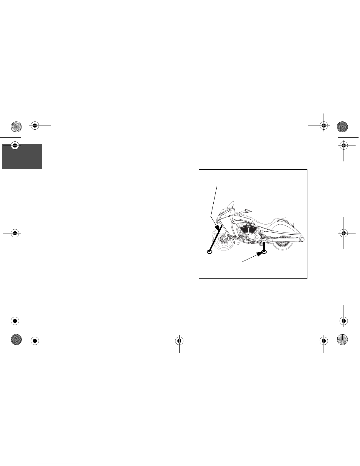
Transporting The Motorcycle
If you must transport the motorcycle, use a truck or
trailer. Do not tow the motorcycle with another
vehicle, as towing will impair the motorcycle’s
steering and handling, which can cause loss of
control.
• Position and restrain the motorcycle so it remains
upright on the truck or trailer, as gasoline may
leak out of the fuel tank if the motorcycle leans to
one side. Gasoline is a fire hazard and it can also
damage the motorcycle’s finish.
• Do not restrain the motorcycle using the
handlebars. In front, hook the tiedowns in the
loop provided in the bottom of the frame. Place
tie-downs as wide apart as possible on the truck
or trailer bed for best stability. Secure the
motorcycle as shown at right.
To loop on frame.
(One tiedown each side)
To shock/strut mount, or rear tip-over bar
(One tiedown each side)
visionownersmanual.book Page 22 Wednesday, February 13, 2008 4:31 PM
Page 26

23
SAFETY
Safety
Fueling Precautions
For complete fueling procedure see page 110. Gasoline is highly flammable and can be
explosive in certain conditions. Observe the following precautions when you refuel or
service the fuel system:
• Turn off the engine.
• Open the fuel cap slowly.
• Add fuel in a well-ventilated area.
• Do not spill gasoline on the engine or the exhaust system. Immediately wipe, or rinse with
water, gasoline spilled on any part of the motorcycle or the surrounding area.
• Do not smoke while fueling.
• Do not fuel in an area where there are sparks or open flames.
visionownersmanual.book Page 23 Wednesday, February 13, 2008 4:31 PM
Page 27

24
SAFETY
Safety
Gasoline and Exhaust Precautions
Gasoline and gasoline vapors are poisonous and can cause severe injury.
• Do not swallow gasoline, inhale gasoline vapors, or spill gasoline on yourself or your
clothes.
• If you swallow gasoline, inhale more than a few breaths of gasoline vapor, or get gasoline
in your eyes, see a physician immediately.
• If you spill gasoline on your skin, wash it off immediately with soap and water. If you spill
gasoline on your clothes, change your clothes immediately.
Exhaust gases contain carbon monoxide, a colorless, odorless gas that can cause
unconsciousness or severe injury or death in a short time. Observe the following
precautions to avoid the effects of exhaust gases:
• Do not inhale exhaust gases.
• Do not start or run the engine in an enclosed area.
visionownersmanual.book Page 24 Wednesday, February 13, 2008 4:31 PM
Page 28

25
SAFETY
Safety
Periodic Maintenance
Failure to perform safety maintenance as recommended can result in difficult handling and
loss of control, which could result in serious injury or death. Always perform the safety
maintenance procedures as recommended. Perform maintenance and repairs promptly
as outlined in the VICTORY service manual, or see your authorized VICTORY dealer for
service.
• Before each ride, complete a pre-ride check as outlined beginning on page 85.
• Perform periodic maintenance according to the intervals outlined in the Periodic
Maintenance Interval tables beginning on page 133.
• Maintain proper tire pressure and tread condition and proper wheel and tire balance.
Inspect tires regularly and replace them if they’re worn or damaged. Use only an
approved replacement tire and see the VICTORY service manual or your authorized
VICTORY dealer for tire replacement.
• Check proper steering head bearing adjustment. Regularly inspect the rear shock
absorber and the front forks. Check for fork oil or shock absorber fluid leaks. Operating
the motorcycle with a loose, worn, or damaged steering system or front or rear
suspension system can make the motorcycle hard to handle and cause loss of control.
visionownersmanual.book Page 25 Wednesday, February 13, 2008 4:31 PM
Page 29
26
SAFETY
Safety
Periodic Maintenance
• Keep the motorcycle clean. In addition to extending the service life and the original
appearance of the motorcycle, a complete and thorough cleaning can reveal items in
need of repair.
• Keep equipment required by federal, state, and local laws in place and in good working
condition. Your license plate must be clean, clearly visible in all conditions, and installed
in a position specified by law.
• Each fastener used in the motorcycle meets our quality specifications for strength, finish
and type. When replacement fasteners are needed, use only genuine VICTORY parts,
tightened to the proper torque. A fastener that does not meet original specifications
could fail and result in damage to the motorcycle or injury to riders.
Electromagnetic Interference
This vehicle complies with European directive 97/24/EC Chapter 8 requirements, which is
equivalent to Canadian ICES-002.
visionownersmanual.book Page 26 Wednesday, February 13, 2008 4:31 PM
Page 30

27
SAFETY
Safety
Gross Vehicle Weight Rating (GVWR)
Gross Vehicle Weight is the maximum allowable weight of the vehicle, and includes the
total weight of the motorcycle, the operator, and the passenger. NEVER exceed the
motorcycle’s Gross Vehicle Weight Rating. Exceeding the weight rating can reduce
stability and handling and could cause loss of control.
• The weight of the motorcycle includes the motorcycle and all of its fluids, any
accessories and their contents, and any additional cargo on the motorcycle.
• The weight of the operator or passenger includes body weight, all apparel and objects
in or on apparel.
• Examples of loading and calculating Gross Vehicle Weight are included on the following
pages. Refer to the specifications section of this manual (beginning on page 239) or to
the certification label (located under the rear console panel in front of the seat) for
additional GVWR information on your specific model.
visionownersmanual.book Page 27 Wednesday, February 13, 2008 4:31 PM
Page 31

28
SAFETY
Safety
Loading Example 1
VICTORY VISION with no cargo or accessories. GVWR = 1414 lbs (641 kg)
Item
Weight
Street Tour
VICTORY VISIONwet weight (full capacity all fluids) 844 lbs. (383 kg) 889 lbs. (403 kg)
Operator - with recommended riding apparel 220 lbs. (100 kg) 220 lbs. (100 kg)
Passenger - with recommended riding apparel 155 lbs. (70 kg) 155 lbs. (70 kg)
Total Weight 1219 lbs. (553 kg) 1264 lbs. (574 kg)
NEVER exceed GVWR. If you have any questions about loading your VICTORY motorcycle safely, please
consult an authorized VICTORY dealer. See “Gross Vehicle Weight Rating (GVWR)” on page 27.
visionownersmanual.book Page 28 Wednesday, February 13, 2008 4:31 PM
Page 32

29
SAFETY
Safety
Loading Example 2
VICTORY VISION with cargo. GVWR = 1414 lbs (641 kg)
Item
Weight
Street Tour
VICTORY VISIONwet weight (full capacity all fluids) 844 lbs. (383 kg) 889 lbs. (403 kg)
Operator - with recommended riding apparel 220 lbs. (100 kg) 220 lbs. (100 kg)
Passenger - with recommended riding apparel 155 lbs. (70 kg) 155lbs. (70 kg)
Total weight of cargo in the saddlebags / trunk 9 lbs. (4 kg) 15 lbs. (7 kg)
Total Weight 1228 lbs. (557 kg) 1279 lbs. (581 kg)
NEVER exceed GVWR. If you have any questions about loading your VICTORY motorcycle safely, please
consult an authorized VICTORY dealer. See “Gross Vehicle Weight Rating (GVWR)” on page 27.
visionownersmanual.book Page 29 Wednesday, February 13, 2008 4:31 PM
Page 33

30
SAFETY
Safety
Loading Example 3
VICTORY VISION with cargo and accessories. GVWR = 1414 lbs (641 kg)
Item
Weight
Street Tour
VICTORY VISION wet weight (full capacity all fluids) 844 lbs. (383 kg) 889 lbs. (403 kg)
Operator - with recommended riding apparel 220 lbs. (100 kg) 220 lbs. (100 kg)
Passenger - with recommended riding apparel 155 lbs. (70 kg) 155lbs. (70 kg)
Total weight of cargo in the saddlebags / trunk 9 lbs. (4 kg) 15 lbs. (7 kg)
Total weight of accessory item & mounting hardware 7 lbs. (3 kg) 7 lbs. (3 kg)
Total Weight 1235 lbs. (560 kg) 1286 lbs. (584 kg)
NEVER exceed GVWR. If you have any questions about loading your VICTORY motorcycle safely, please
consult an authorized VICTORY dealer. See “Gross Vehicle Weight Rating (GVWR)” on page 27.
visionownersmanual.book Page 30 Wednesday, February 13, 2008 4:31 PM
Page 34

31
SAFETY
Safety
Safety and Information Labels - VIN Decal
Location of Vehicle Identification Number decal - on frame under rear console cover.
See “Seat Removal / Installation” on page 190.
VIN decal
VIN Number
Tire & Wheel Information
Date of Manufacture
(under rear console panel)
Operator / Fuel warning on outside of panel
GAWR Information
GVWR Information
3safety.fm Page 31 Tuesday, February 3, 2009 11:50 AM
Page 35

32
SAFETY
Safety
Safety and Information Labels - VECI Decal
Location of Vehicle Emission Control Information decal - inside left saddlebag.
VECI decal
3safety.fm Page 32 Tuesday, February 3, 2009 11:50 AM
Page 36

33
SAFETY
Safety
Safety and Information Labels - NECI Decal
Location of Noise Emission Control Information decal - inside left saddlebag.
NECI decal (below VECI decal)
Windshield decal
3safety.fm Page 33 Tuesday, February 3, 2009 11:50 AM
Page 37

34
SAFETY
Safety
Safety and Information Labels - Tire Information & Cargo Decals
Location of Tire Information decal - inside left saddlebag door
Tire Information decal
Cargo decals inside bags (and trunk if equipped)
3safety.fm Page 34 Tuesday, February 3, 2009 11:50 AM
Page 38

35
SAFETY
Safety
Reporting Safety Defects
If you believe that your vehicle has a defect that could result in a crash or cause injury or
death, you should immediately inform the National Highway Traffic Safety Administration
(NHTSA) in addition to notifying Polaris Industries in writing.
If NHTSA receives similar complaints, it may open an investigation, and if it finds that a
safety defect exists in a group of vehicles, it may order a recall and remedy campaign.
However, NHTSA cannot become involved in individual problems between you, your
dealer or Polaris Industries.
To contact NHTSA, or obtain other information about motor vehicle safety, you may either
call the Vehicle Safety Hotline toll-free at 1-888-327-4236 (TTY: 1--800--424--9153), visit
the NHTSA website at www.safercar.gov, or write to:
NHTSA
U.S. Department of Transportation
400 7th Street Southwest
Washington, DC 20590
visionownersmanual.book Page 35 Wednesday, February 13, 2008 4:31 PM
Page 39

36
SAFETY
Safety
NOTES
visionownersmanual.book Page 36 Wednesday, February 13, 2008 4:31 PM
Page 40

37
IDENTIFICATION
I.D.
Identification Numbers
Vehicle Identification Number
The Vehicle Identification Number is printed on
the Manufacturer Information Decal located
under the rear console cover on the frame.
See “Seat Removal / Installation” on
page 190.
Record this number in the space provided on
page 40 and have it available as it is
sometimes required when ordering parts or
accessories.
The VIN is also stamped into the right side of
the frame near the steering head.
VIN on frame
Manufacturer (VIN) Decal under cover
4component identification.fm Page 37 Tuesday, February 3, 2009 12:54 PM
Page 41

38
IDENTIFICATION
I.D.
Engine Number
The engine number is stamped into the right crankcase
behind the rear cylinder (1).
Record the number in the space provided on page 40.
VECI / NECI & Tire Information Decals
The Vehicle Emission Control Information (VECI), Noise
Emission Control Information (NECI), and the Tire
Information decals are located in the left saddlebag and on
the bag door.
1
VECI / NECI / Tire Decal
4component identification.fm Page 38 Tuesday, February 3, 2009 12:54 PM
Page 42

39
IDENTIFICATION
I.D.
Ignition Key Number
The ignition key number is stamped on the
small metal tag (1) attached to the key ring.
Remove the tag and record the number on
page 40. Store the tag in a safe place.
Additional keys can be copied from one of the
original keys (VICTORY key blank required).
If you lose both original keys, you will need the
following:
• Key number (recorded previously)
• A new key blank (purchased from your
VICTORY dealer)
• Proof of ownership
• A lock smith or VICTORY dealer with the
equipment necessary to cut a new key
1
4component identification.fm Page 39 Tuesday, February 3, 2009 12:54 PM
Page 43

40
IDENTIFICATION
I.D.
Record important numbers below for reference:
VIN Number Record
Engine I.D. Record
Ignition Key Number Record
4component identification.fm Page 40 Tuesday, February 3, 2009 12:54 PM
Page 44

41
IDENTIFICATION
I.D.
Component Location - Left View
Left Side View
1. Spark Plugs
2. Front Brake Caliper (left)
3. Gear Shift Pedal
4. Operator’s Footrest
5. Sidestand
6. Oil Drain Plug
7. Oil Filter
8. Passenger’s Footrest
9. Rear Brake Caliper
10. Diagnostic Connector (in left bag)
11. Running Light (Tour)
12. Rear Speakers (Tour)
13. Passenger Hand Grip
14. Rear Shock Air Fitting (under left saddlebag door)
5 6
7 8
3
4
9
11
2
1
1214 13
10
4component identification.fm Page 41 Tuesday, February 3, 2009 12:54 PM
Page 45

42
IDENTIFICATION
I.D.
Component Location - Right View
Right Side View
1. Drive Belt Guard
2. Drive Belt
3. Passenger’s Footrest
4. Drive Sprocket (under cover)
5. Speed Sensor (top of crankcase)
6. Engine Oil Fill Cap / Dipstick
7. Rear Brake Pedal
8. Operator’s Footrest
9. Front Brake Caliper (right)
10. Passenger Hand Grip
11. Reflector
32 4 5 61 7 8 9
1011
4component identification.fm Page 42 Tuesday, February 3, 2009 12:54 PM
Page 46

43
IDENTIFICATION
I.D.
Component Location - Front View
Front View
1. Front Turn Signal (outer light, each side)
2. Wind Deflector (one each side)
3. Headlamp (high beam)
4. Headlamp (low beam)
5. Driving Lamp (or HID lamp if equipped)
6. Air Filter (front of frame)
7. Tiedown Loop (on frame)
8. Rear Brake Fluid Reservoir
9. Battery
10. Oil Cooler
11. Horn
12. Evaporative Emissions Canister
13. Fuel Tank (one each side)
14. Running Light (inner light, each side)
3
9
2
1
5
6
10
11
12
14
8
7
4
13
4component identification.fm Page 43 Tuesday, February 3, 2009 12:54 PM
Page 47

44
IDENTIFICATION
I.D.
Component Location - Rear View
Rear View
1. Turn Signals (uppermost in lens)
2. Tail Lamps (3 each side; all tail bulbs are ON
with lights)
3. Brake Lamps (four lower bulbs illuminate
brightly when brake is applied with turn
signal OFF; bottom two only with turn signal
ON)
4. Exhaust Muffler
5. License Plate Bracket
2
3
1
6
4
4
visionownersmanual.book Page 44 Wednesday, February 13, 2008 4:31 PM
Page 48

45
IDENTIFICATION
I.D.
Component Location - Top View
Top View
1. Windshield (radio antenna is under dash)
2. Left Mirror
3. Clutch Fluid Reservoir
4. Clutch Lever
5. Glove Compartment Door
6. Operator Seat
7. Passenger Seat
8. Left Saddlebag Latch
9. Trim Panel - Street Model (or Tour w/ Trunk
Removed)
10. Right Saddlebag Latch
11. Front Brake Lever
12. Front Brake Fluid Reservoir
13. Fuel Filler Cap Access Door
14. Right Mirror
15. Reverse Lever (if equipped)
7
3
4
2
5
6
1
12
11
13
14
8
9
10
15
4component identification.fm Page 45 Tuesday, February 3, 2009 1:27 PM
Page 49

46
IDENTIFICATION
I.D.
Component Location - Rider’s View
Rider’s View
(See INSTRUMENTS, FEATURES, &
CONTROLS for more information)
1. Speaker (left)
2. Fuel Gauge
3. Speedometer
4. Indicator Lamp Display
5. Information Display
6. Tachometer
7. Volt Meter
8. Speaker (Right)
9. Cruise Control Switches
10. Radio Controls
11. Left Handlebar Switch / Audio Control
871 3 4 52 6
9
10
11
visionownersmanual.book Page 46 Wednesday, February 13, 2008 4:31 PM
Page 50

47
INSTRUMENTS, FEATURES, & CONTROLS
Controls
Ignition Key
The ignition key operates the ignition switch, fuel
door (page 77) bag locks (page 81) and trunk lock
(if equipped, page 82). Key position and function
is described on the following pages.
Keep the spare key (provided) in a safe place
separate from the main key.
Be careful what style of key ring you use, as some
larger rings or those made of metal can scratch
the finish on the console.
CAUTION
Before starting the engine, read engine starting
instructions beginning on page 112.
LOCKED
OFF ACC
ON
FUEL DOOR
OPEN
(PUSH)
visionownersmanual.book Page 47 Wednesday, February 13, 2008 4:31 PM
Page 51

48
INSTRUMENTS, FEATURES, & CONTROLS
Controls
Ignition Switch
Place the ignition key in the ignition switch to operate the following functions of the switch.
IGNITION SWITCH FUNCTION
OFF All electrical circuits are off. The ignition key can be removed.
ON
All electrical circuits are on. The ignition key cannot be removed. Taillight, running
lights, radio and instrument lights illuminate. Headlight can be turned on by either
tapping or pressing the start button. Hazard flashers and turn signals can be activated.
ACC
Power is supplied to accessory circuits, radio, instruments, turn signals, brake light,
windshield motor, horn and hazard (flasher). The key can be removed.
LOCK
All electrical circuits are off. The ignition key can be removed. The glove compartment
is locked when the steering is locked.
FUEL
DOOR
See page 77.
visionownersmanual.book Page 48 Wednesday, February 13, 2008 4:31 PM
Page 52

49
INSTRUMENTS, FEATURES, & CONTROLS
Controls
Instrument Cluster
The instrument cluster includes the items listed
on the following pages. The MODE button
(page 62) is used to toggle through various
functions, change unit display (mph to kph) and
to reset all functions except the odometer and
fuel range.
Speedometer
The speedometer displays current motorcycle
speed in miles per hour (mph) or kilometers per
hour (kph) (International). See page 54.
Tachometer
The tachometer displays current engine speed in revolutions per minute (RPM). A red line
on the face indicates maximum safe engine RPM.
WARNING
Do not exceed red line. Excessive RPM could cause engine damage or failure that could
result in loss of control.
Speedometer
Tachometer
visionownersmanual.book Page 49 Wednesday, February 13, 2008 4:31 PM
Page 53

50
INSTRUMENTS, FEATURES, & CONTROLS
Controls
Fuel Gauge
The fuel gauge operates when the key is in the
ON or ACC position. For most accurate
readings, sit on the motorcycle and bring it to
an upright position.
Volt Meter
The volt meter displays battery voltage being
supplied to main electrical circuits when the
key is in the ON position.
The meter will display approximate battery
voltage when the key is ON without the engine running. With the engine running, the
meter will display approximate battery charging voltage.
Fuel Gauge
Vol t Meter
visionownersmanual.book Page 50 Wednesday, February 13, 2008 4:31 PM
Page 54

51
INSTRUMENTS, FEATURES, & CONTROLS
Controls
Indicator Lamp Display
The indicator lamps are located on the upper
display in the center of the instrument panel.
See the following pages for a description of
each and its function.
Information Display
The information display, located below the
indicator lamp display, is a multi-function LCD
unit. This panel will display time, gear position,
ambient temperature, mileage (either trip or
total vehicle mileage), fuel range, average
MPG, current fuel economy, trip time, and other trip information. Use the MODE button
(page 62) to toggle through the feature. Each feature is described in more detail in this
chapter. See page 54 to change the unit display (U.S. to Metric).
NOTE:
If “Err” displays while toggling through the features, a system error has been logged. See
“Check Engine” indicator information on page 59.
Indicator Lamp Display
Information Display
visionownersmanual.book Page 51 Wednesday, February 13, 2008 4:31 PM
Page 55

52
INSTRUMENTS, FEATURES, & CONTROLS
Controls
Clock
1. Turn the key to ON or ACC to view the clock. To change the
setting, use the MODE button to toggle to the odometer.
2. Press and hold the MODE button until the hour segment
flashes, then release the button. Tap the MODE button to
advance to the desired setting.
NOTE:
If LOW FUEL is flashing, the display will not enter the CLOCK
SET mode.
3. Repeat step 2 to set the 10-minute and 1-minute segments, then press and hold the
MODE button to save the settings and exit the CLOCK SET mode.
4. Turn the key off. The clock is set until the
battery is disconnected or discharged.
Error Screen
If “Err” appears in the clock area, record the three
code numbers displayed on the screen. See an
authorized VICTORY dealer for code details. See
“Check Engine” indicator information on page 59.
Clock
Avg
C
F
8
881
88
:
88
8.88
:
88:8
Speed Range Inst Time
TRIP 1
TRIP 2
km / h
miles / gah
Error Code
Number (0-9)
“Err”
Suspect Parameter Number (SPN)
Failure Mode
Indicator (FMI)
visionownersmanual.book Page 52 Wednesday, February 13, 2008 4:31 PM
Page 56

53
INSTRUMENTS, FEATURES, & CONTROLS
Controls
Gear Position
The number of the current transmission gear is
displayed with the key in the ON position and
the Stop/Run switch in RUN. “N” displays in
neutral. “R” displays in reverse (if equipped).
Trip Odometer
The trip odometer shows total miles traveled
since the trip odometer was reset. Use the
MODE button to toggle between odometer and
trip meter. To reset the trip meter:
1. Turn the key to ON and toggle to the trip
meter.
2. Hold the MODE button until the trip meter
resets.
Temperature
Current ambient air temperature is displayed with the key in the ON or ACC position.
Gear Position
Trip Odometer
Temperature
visionownersmanual.book Page 53 Wednesday, February 13, 2008 4:31 PM
Page 57

54
INSTRUMENTS, FEATURES, & CONTROLS
Controls
Odometer
The odometer displays total mileage of the
vehicle in miles or kilometers. See “Trip
Odometer” on page 53 to change the odometer
display to trip meter.
To Change Display Units
To change the odometer display from English
(miles & 12-hour clock) to Metric (kilometers and
24-hour clock):
1. With the key OFF, press and hold the MODE
button.
2. Turn the key to ON or ACC.
3. Toggle the MODE button to the desired screen display unit.
4. Press and hold the MODE button until the display returns to the TRIP computer.
Odometer
visionownersmanual.book Page 54 Wednesday, February 13, 2008 4:31 PM
Page 58

55
INSTRUMENTS, FEATURES, & CONTROLS
Controls
CONSOLE MOUNTED SWITCHES
The console mounted switches are used to control the
following features:
• Handgrip Heaters (if equipped)
• Hazard (emergency flashers)
• Driving lamp (center headlamp)
• Accessory switch location (blank)
Refer to the following pages for switch function.
2. Hazard
3. Driving lamp
1. Hand grip heater
4. Accessory switch location
2
1
3
4
visionownersmanual.book Page 55 Wednesday, February 13, 2008 4:31 PM
Page 59

56
INSTRUMENTS, FEATURES, & CONTROLS
Controls
Hand Grip Heater Switch
Press the rocker switch toward the Hi or Low
position, depending on the amount of heat required.
Press the rocker switch to the middle position to turn
the grip heaters OFF.
Hazard Switch (Emergency Flashers)
The Hazard switch activates and de-activates the
emergency flashers. When the emergency flashers
are active, all of the turn signals flash.
To activate the emergency flashers:
• Press the rocker switch toward the triangle to turn
the emergency flashers ON.
• Press the rocker switch away from the triangle to
turn the emergency flashers OFF.
Hazard ON
Hazard OFF
Grip Heat HIGH
Grip Heat OFF
visionownersmanual.book Page 56 Wednesday, February 13, 2008 4:31 PM
Page 60

57
INSTRUMENTS, FEATURES, & CONTROLS
Controls
Driving Lamp Switch
When the ignition key is ON, the driving lamp switch
operates the center headlamp or HID lamp (if equipped).
The driving lamp is not controlled by the high / low beam
switch. It is an additional low beam lamp that can be on at all
times if selected on the console.
To activate the driving lamp:
• Press the rocker switch toward the headlamp icon to turn
the driving lamp ON.
• Press the rocker switch away from the icon to turn the
driving lamp OFF.
Driving Lamp ON
Driving Lamp OFF
visionownersmanual.book Page 57 Wednesday, February 13, 2008 4:31 PM
Page 61

58
INSTRUMENTS, FEATURES, & CONTROLS
Controls
Neutral, Gear Position, & High Beam Indicator Lamps
Gear Position
Transmission gear selection appears in the information display (6th
gear shown). On models equipped with reverse, “R” displays when
the reverse lever is engaged. See page 127.
Neutral
The neutral indicator lamp illuminates when the transmission is in
neutral (and the ignition key is in the ON or ACC position).
High Beam
This lamp illuminates when the head lamp switch is set to HIGH
BEAM.
Neutral Light
Gear Position
High Beam
Oil Pressure
Low Fuel
Check Engine
Cruise Control
Right Turn
Left Turn
Low Battery
6
visionownersmanual.book Page 58 Wednesday, February 13, 2008 4:31 PM
Page 62

59
INSTRUMENTS, FEATURES, & CONTROLS
Controls
Check Engine & Turn Signal Indicator Lamps
Check
Engine
This indicator illuminates momentarily when the ignition switch is ON and
the engine is stopped. The light will illuminate if the tilt sensor has shut
down the engine. If systems report abnormal sensor or engine operation
(with ignition key ON), the indicator illuminates as long as the fault
condition exists. An error code menu can be viewed in the information
display. Use the MODE button to toggle until "Err" is displayed and record
the information shown. See an authorized VICTORY dealer for code
details. NOTE: Codes are not stored. The "Err" screen displays only when
the check engine light is on, or goes on and off during one ignition cycle.
When the key is turned OFF, the code and message is lost, but will
reappear if the fault reoccurs after restarting the engine. NOTICE: If the
Check Engine Indicator illuminates while the engine is running, see an
authorized VICTORY dealer promptly for diagnosis.
Turn
Signal
This indicator flashes the left or right arrow, or both (hazard) when turn or
hazard is activated. If a turn signal bulb has failed, or if there is a short
circuit in the turn signal system, the turn signal indicator flashes at more
than twice the normal rate.
(L)
(R)
visionownersmanual.book Page 59 Wednesday, February 13, 2008 4:31 PM
Page 63

60
INSTRUMENTS, FEATURES, & CONTROLS
Controls
Oil Pressure & Low Fuel Indicator Lamps
Engine Cruise Control Indicator Lamp
Low Oil Pressure
The Low Oil Pressure indicator illuminates when the ignition switch
is in the ON position and the engine is not running. This means the
indicator circuit is functioning properly. The indicator also
illuminates when oil pressure drops below safe operating pressure.
If this indicator illuminates while engine is running, turn the engine
off as soon as safely possible and check the oil level. If the oil level
is correct and the indicator remains illuminated after the engine is
restarted, turn the engine off immediately.
Low Fuel
The Low Fuel indicator illuminates when approximately one gallon
(3.8 liters) of fuel remains in the fuel tank.
Cruise Control
The Cruise Control indicator illuminates when the cruise control
power is ON and a set speed is selected. See Cruise Control
Safety & Operation beginning on page 120 before using the cruise
control.
visionownersmanual.book Page 60 Wednesday, February 13, 2008 4:31 PM
Page 64

61
INSTRUMENTS, FEATURES, & CONTROLS
Controls
Seat Heater Switches
The seat heater switches (if equipped) are
located on the seat under the left passenger
hand grip.
The driver and passenger seat heater settings
are independently controlled. The front switch
controls the driver’s seat and the rear switch
controls the passenger’s seat.
CAUTION
LOW position is sufficient for most ambient
temperatures and riding apparel. Use HIGH
with caution.
Off
LowHigh
Front
Location
Switch
OFF - Set switch in the center position
LOW - Set switch in the rearward position
HIGH - Set switch in the forward position
visionownersmanual.book Page 61 Wednesday, February 13, 2008 4:31 PM
Page 65

62
INSTRUMENTS, FEATURES, & CONTROLS
Controls
LEFT HANDLEBAR SWITCH
Mode Button
The MODE button is located on the front side of
the left handlebar switch.
The MODE button is used to toggle through the
various Information display items available, and
to change the display from English (miles) to
Metric (kilometers).
Refer to the individual display feature
throughout this chapter for more information.
NOTE:
If “Err” displays while toggling through the
features, a system error has been logged.
See “Check Engine” indicator information on
page 59.
LEFT Handlebar Switch
visionownersmanual.book Page 62 Wednesday, February 13, 2008 4:31 PM
Page 66

63
INSTRUMENTS, FEATURES, & CONTROLS
Controls
Headlamp High / Low Beam Switch
To turn the headlamp on, turn the ignition key
to ON and tap or press the start button. The
headlamp high/low beam switch toggles the
headlamp between high and low beam.
• To activate the high beam, press the upper
portion of the switch.
• To activate the low beam, press the lower
portion of the switch.
High Beam
Low Beam
LEFT Handlebar Switch
visionownersmanual.book Page 63 Wednesday, February 13, 2008 4:31 PM
Page 67

64
INSTRUMENTS, FEATURES, & CONTROLS
Controls
Windshield Adjustment Switch (Motorized)
The motorized windshield adjustment switch
changes the height (and angle) of the windshield.
This button is active with the key in the ON or ACC
position.
• To move the windshield UP, press the upper
portion of the switch.
• To move the windshield DOWN, press the lower
portion of the switch.
NOTE:
Do not continuously cycle windshield more than
once in a 60 second period.
If your motorcycle is not equipped with a motorized
windshield adjustment, see Manual Windshield
Adjustment on page 76.
UP
DOWN
LEFT Handlebar Switch
visionownersmanual.book Page 64 Wednesday, February 13, 2008 4:31 PM
Page 68

65
INSTRUMENTS, FEATURES, & CONTROLS
Controls
Turn Signal Switch
Use the turn signal switch to activate a turn signal. The
key must be in the ON or ACC position.
Turn signals automatically cancel after predetermined
speed and distance conditions are met. To manually
cancel a signal, move the switch to the center position
and press it inward
• Push the switch to the left to activate the left turn
signals.
• Push the switch to the right to activate the right turn
signals.
Turn
LEFT Handlebar Switch
visionownersmanual.book Page 65 Wednesday, February 13, 2008 4:31 PM
Page 69

66
INSTRUMENTS, FEATURES, & CONTROLS
Controls
Turn Signal Momentary Feature
The momentary signal feature is useful when passing
or changing lanes. To use the momentary feature, push
and hold the switch through at least one complete flash
cycle (at least one second) to activate the feature. The
signal will then cancel the moment the switch is
released.
Horn Button
With the ignition key in the ON or ACC position, press
the horn button to sound the horn.
Hold Left or
Horn
Right for one
flash cycle
visionownersmanual.book Page 66 Wednesday, February 13, 2008 4:31 PM
Page 70

67
INSTRUMENTS, FEATURES, & CONTROLS
Controls
Clutch Lever
To disengage the clutch, pull the lever toward the
handlebar. To engage the clutch, gradually release
the lever. For smooth clutch operation, pull the lever
quickly and release it gradually.
Starter Interlock
The motorcycle is equipped with a starter interlock
switch that prevents the electric starter from
operating when the transmission is in gear and the
clutch is engaged (lever released).
Read complete engine starting procedures
beginning on page 112 before starting the engine.
CAUTION
Never start the motorcycle in gear with the clutch
disengaged unless you are seated on the bike in a
normal riding position with the front brake applied.
LEFT Handlebar
Interlock Switch
Clutch Lever
visionownersmanual.book Page 67 Wednesday, February 13, 2008 4:31 PM
Page 71

68
INSTRUMENTS, FEATURES, & CONTROLS
Controls
RIGHT HANDLEBAR CONTROLS
Engine Stop / Run Switch
The engine stop/run switch completes or interrupts
the ignition, starter, and fuel pump circuits.
To complete the circuits, allowing the engine to start
and run, press the lower portion of the engine stop/
run switch (RUN position).
To interrupt the circuits, press the upper portion of
the switch (STOP position). The engine should not
start or run when the switch is in the STOP position.
Use the engine stop/run switch to turn the engine off
under either normal or emergency conditions. Turn
the key OFF after the engine stops.
Run
RIGHT Handlebar Switch
visionownersmanual.book Page 68 Wednesday, February 13, 2008 4:31 PM
Page 72

69
INSTRUMENTS, FEATURES, & CONTROLS
Controls
Engine Starter Button
The engine starter button is used to start the engine,
activate the headlight, and operate in reverse gear (if
equipped).
To start the engine, the engine stop/run switch must be in
the RUN position. The transmission must be in neutral (or
the clutch must be disengaged) and the reverse lever (if
equipped) must be disengaged. Press the right side of the
starter button to engage the starter.
NOTE:
Read the engine starting procedure beginning on
page 112 before starting the engine.
To activate the headlight, the ignition switch must be on.
Tap the starter button to turn the headlight on without
starting the engine.
To operate in reverse, see page 127
Start
RIGHT Handlebar Switch
visionownersmanual.book Page 69 Wednesday, February 13, 2008 4:31 PM
Page 73

70
INSTRUMENTS, FEATURES, & CONTROLS
Controls
Throttle Control Grip
The throttle control grip controls the engine speed.
To increase engine speed and power, twist the top of
the throttle control grip toward you (A).
To decrease engine speed and power, twist the top
of the grip away from you (B).
Mirrors
The rear view mirrors are adjusted by applying light
pressure to left, right, top, or bottom edge (C).
Throttle Control Grip
A
B
C
visionownersmanual.book Page 70 Wednesday, February 13, 2008 4:31 PM
Page 74

71
INSTRUMENTS, FEATURES, & CONTROLS
Controls
Linked Braking System
The front and rear brakes on the motorcycle are
linked.
Application of the front brake lever activates only the
front brakes.
Application of the rear brake pedal activates the rear
brake caliper fully, while simultaneously activating
one of the three pistons in each front brake caliper.
For maximum brake effectiveness, the front brake
lever and rear brake pedal should be applied
together, as you would with a conventional (nonlinked) brake system.
visionownersmanual.book Page 71 Wednesday, February 13, 2008 4:31 PM
Page 75

72
INSTRUMENTS, FEATURES, & CONTROLS
Controls
Front Brake Lever
The front brake lever is located on the right
handlebar.
To apply the front brake, pull the lever toward the
handlebar. As described on page 71, the front brake
lever activates only the front brake calipers.
See “Braking” on page 124 for braking procedures in
various riding conditions.
Lever “reach” or distance to the hand grip is
adjustable. To adjust the front brake lever reach:
• Pull the lever away from the grip (1) and hold.
• Turn dial (2) to align a lower number with the arrow
(3) on the lever to increase lever reach distance.
• Turn the dial to align a higher number with the
arrow on the lever to decrease reach distance.
1
3
2
visionownersmanual.book Page 72 Wednesday, February 13, 2008 4:31 PM
Page 76

73
INSTRUMENTS, FEATURES, & CONTROLS
Controls
Rear Brake Pedal
The rear brake pedal is on the right side of the
motorcycle.
To apply the rear brake, press down on the rear
brake pedal. As described on page 71, a small
amount of front brake is also applied.
See page 124 for braking procedures in various
riding conditions.
Brake Pedal
visionownersmanual.book Page 73 Wednesday, February 13, 2008 4:31 PM
Page 77

74
INSTRUMENTS, FEATURES, & CONTROLS
Controls
Gear Shift Pedal
The gear shift pedal is located on the left side of the
motorcycle.
• To shift to a lower gear, press down on the gear
shift pedal.
• To shift to a higher gear, lift up on the gear shift
pedal.
See page 114 through page 117 for proper gear
shifting procedures.
Shift Pedal
visionownersmanual.book Page 74 Wednesday, February 13, 2008 4:31 PM
Page 78

75
INSTRUMENTS, FEATURES, & CONTROLS
Controls
Foot Control Adjustment
The brake pedal and shift pedal can be adjusted to
one of three positions. The controls are in the center
position as delivered from VICTORY.
To move the controls to the front or rear position, do
the following:
1. Use a 6mm Allen wrench to remove screw (1).
2. Slide the control forward or rearward in its track
until the threaded hole of the control aligns with
the front (2) or rear (3) screw hole in the footrest
support.
3. Reinstall the screw and torque to 96 lb-in. (11 Nm).
4. After adjusting the shift pedal, always readjust the shift linkage rod. Loosen both jam
nuts on the linkage and turn the shaft until the footpeg is about 90mm from the
floorboard (or to desired height). Tighten both jam nuts to 96 lb-in. (11 Nm).
1
2
3
visionownersmanual.book Page 75 Wednesday, February 13, 2008 4:31 PM
Page 79

76
INSTRUMENTS, FEATURES, & CONTROLS
Controls
Manual Windshield Adjustment
If your motorcycle is not equipped with a motorized
windshield, you can adjust it manually using the following
procedure:
1. Stop the motorcycle and turn the key OFF.
2. Remove the windshield trim panel (see page 184).
3. Remove the retaining clip (1).
4. Hold slight downward pressure on the bottom of the
windshield (it is under slight upward spring pressure).
5. Remove the clevis pin (2), slide the windshield inner
bracket to align with one of the optional holes in the
outer bracket, then reinstall the clevis pin.
6. Install the retaining clip in the clevis pin.
7. Install the windshield trim panel (page 184).
1
2
visionownersmanual.book Page 76 Wednesday, February 13, 2008 4:31 PM
Page 80

77
INSTRUMENTS, FEATURES, & CONTROLS
Controls
Fuel Door
Use the ignition key to unlock the fuel door.
1. Turn the key to the OFF position.
2. Turn the handlebars full left.
NOTE:
Do not push the key down when unlocking the fuel
door.
3. Turn the key counter-clockwise to release the fuel
door latch. The door will open under light spring
tension.
NOTE:
See page 23 and page 110 for fueling instructions.
Turn key
counterclockwise
to open fuel door.
Do not depress key.
5instruments.fm Page 77 Thursday, February 14, 2008 8:14 AM
Page 81

78
INSTRUMENTS, FEATURES, & CONTROLS
Controls
Fuel Cap
Use the ignition key to unlock the fuel door.
1. Turn the fuel cap counterclockwise to open.
2. Set the cap in the holder while fueling.
3. To install the cap, turn the fuel cap clockwise until
seated.
4. Close the fuel door. The door is locked when the
key is removed.
NOTE:
For fueling procedure and safety, see Fueling and
Fill Height, page 23 and page 110.
Cap Holder
visionownersmanual.book Page 78 Wednesday, February 13, 2008 4:31 PM
Page 82

79
INSTRUMENTS, FEATURES, & CONTROLS
Controls
Glove Compartment
To OPEN the glove compartment:
• Turn the handlebars to clear the door. Press and
release the inner edge of the door. The door will
open under spring pressure.
To CLOSE the glove compartment:
• Push the door firmly until latched, then release.
To LOCK the glove compartment:
• Close the glove compartment door.
• Turn the ignition key to the lock position.
NOTE:
The glove compartment is locked when the steering
is locked.
visionownersmanual.book Page 79 Wednesday, February 13, 2008 4:31 PM
Page 83

80
INSTRUMENTS, FEATURES, & CONTROLS
Controls
Sidestand
The sidestand is located on the left side of the
motorcycle.
• To extend the sidestand, swing it out from the end
until it is fully extended. Lean the motorcycle toward
the sidestand until it firmly supports the motorcycle.
• To retract the sidestand, lean the motorcycle away
from the sidestand until the motorcycle is fully upright.
Swing the sidestand back into its fully retracted
position.
WARNING
Correctly retract the sidestand before operating the
motorcycle. An improperly retracted sidestand could
come into contact with the ground and cause a loss of
control.
visionownersmanual.book Page 80 Wednesday, February 13, 2008 4:31 PM
Page 84

81
INSTRUMENTS, FEATURES, & CONTROLS
Controls
Saddlebags
The saddlebags can be locked with the ignition key.
Lock the saddlebags when riding.
To UNLOCK the saddlebag:
1. Insert key in bag lock and rotate clockwise to the
unlocked position.
2. Remove the key.
3. Press the bag lock to open the bag door.
4. Refer to loading information beginning on page 27.
To LOCK the saddlebag:
1. Close bag door and insert key.
2. Rotate key counterclockwise to lock position.
3. Remove the key.
U
N
L
O
C
K
L
O
C
K
visionownersmanual.book Page 81 Wednesday, February 13, 2008 4:31 PM
Page 85

82
INSTRUMENTS, FEATURES, & CONTROLS
Controls
Trunk Operation
The trunk can be locked with the ignition key.
Lock the trunk when riding.
To UNLOCK the trunk:
1. Insert key in trunk lock and rotate key to the
vertical position to unlock.
2. Remove the key.
3. Press the trunk lock to open.
4. Observe trunk cargo load limits.
5. Refer to page 27 for loading information.
U
N
L
O
C
K
L
O
C
K
visionownersmanual.book Page 82 Wednesday, February 13, 2008 4:31 PM
Page 86

83
INSTRUMENTS, FEATURES, & CONTROLS
Controls
Radio / Audio Systems
Refer to the Audio section of this manual
(beginning on page 251) for radio and
accessory audio systems operation.
Radio Panel
visionownersmanual.book Page 83 Wednesday, February 13, 2008 4:31 PM
Page 87

84
INSTRUMENTS, FEATURES, & CONTROLS
Controls
Tool Kit
The tool kit can be used to perform most of
the basic maintenance items and some of the
general repairs.
1. 4mm Ball Drive Allen Wrench
2. 4mm / 6mm Open End Wrench
3. 6mm Ball Drive Allen Wrench
4. 8mm / 10mm Open End Wrench
5. Combination Phillips / Slot Screw Driver
6. Rear Shock Absorber / Tire Pressure
Gauge
7. Fuse Puller
21 3
4
5
6
7
visionownersmanual.book Page 84 Wednesday, February 13, 2008 4:31 PM
Page 88

85
PRE-RIDE CHECKS
Pre-Ride
Pre-Ride Checks
Before Each Ride
Perform the checks described in this section before each ride to keep your motorcycle in
good operating condition. This is specially important before making a long trip or when
removing the motorcycle from storage. You must be familiar with the instruments and
controls on your motorcycle to make these checks. When inspections reveal the need for
adjustment, replacement or repair:
• refer to the maintenance section of this manual
• refer to the service manual
• or see your authorized VICTORY dealer
NOTE:
During the pre-ride check you may use products that are potentially hazardous, such as oil
or brake fluid. When using any of these products, always follow the instructions and
warnings on the product packaging.
WARNING
Failure to perform the recommended pre-ride checks could result in component failure
while riding, which could result in serious injury or death. Always perform the pre-ride
checks before each ride. When inspection reveals the need for adjustment, replacement or
repair, perform the service promptly.
visionownersmanual.book Page 85 Wednesday, February 13, 2008 4:31 PM
Page 89

86
PRE-RIDE CHECKS
Pre-Ride
Check Electrical Equipment
Turn the ignition key to the ON position and move the stop/run switch to RUN before
performing the following electrical inspections. Return the ignition key to the OFF position
after completing these inspections. If inspection of any electrical item reveals component
failure, repair or replace the component before operating the motorcycle.
Item Inspection Procedure
Headlamp Tap the starter button to verify that the headlamp illuminates. Switch to high
beam. Verify that the high beam indicator comes on and that lamp brightness
increases.
Taillight/Brake Light Verify that the taillight and license plate light illuminate. If a turn signal is
activated, only the two lower lamps will illuminate. Verify that the taillight
lamps increase in brightness when the front brake lever is applied and also
when the rear brake pedal is applied.
Turn Signals Move the turn signal switch to the left. Verify that front and rear left turn
signals flash, as well as the corresponding light on the indicator panel. Push
the switch inward to cancel the signal. Verify that the signals and the indicator
light stop flashing. Repeat the procedure for the right turn signals.
visionownersmanual.book Page 86 Wednesday, February 13, 2008 4:31 PM
Page 90

87
PRE-RIDE CHECKS
Pre-Ride
Check Electrical Equipment (Cont.)
Item Inspection Procedure
Emergency
Flashers
Press the top of the hazard switch to turn the flashers on. Verify that all four
turn signals flash, as well as the lamps on the indicator panel. Turn the
flashers off. Verify that all signals and indicator lamps stop flashing.
Horn Press the horn button. Verify that the horn sounds loudly.
Neutral Indicator Place the transmission in neutral. Verify that the neutral indicator lamp
illuminates and that the letter “N” displays in the gear position display.
Low Oil Pressure
Indicator
Verify that the low oil pressure lamp illuminates. Start the engine and verify
that the low oil pressure lamp goes off.
Engine Stop/Run
Switch
Start the engine. Move the stop/run switch to the STOP position. Verify that
the engine stops. Attempt to restart the engine to verify that the engine WILL
NOT start.
visionownersmanual.book Page 87 Wednesday, February 13, 2008 4:31 PM
Page 91

88
PRE-RIDE CHECKS
Pre-Ride
Check Engine Oil Level
A dipstick attached to the oil fill cap registers the engine
oil level.
1. With the transmission in neutral, start and run the
engine for several minutes to bring it to operating
temperature.
2. Shut the engine off and wait for 3-5 minutes.
3. Straddle the motorcycle on level ground and bring it
to a vertical position.
4. Remove the oil fill cap/dipstick (1) and wipe it clean.
Reinstall the dipstick and turn the cap clockwise
until it seats.
Approx. 1/2 qt.
1
visionownersmanual.book Page 88 Wednesday, February 13, 2008 4:31 PM
Page 92

89
PRE-RIDE CHECKS
Pre-Ride
5. Remove the dipstick and read the oil level.
6. If necessary, add or remove oil to bring the level into
the area on the dipstick above the ADD mark and
below the FULL mark. See “Engine Oil
Specification” on page 248.
WARNING
Do not operate the motorcycle with the oil level above
the FULL mark or below the ADD mark. Operating the
engine with too much or too little oil can cause serious
engine damage or engine seizure, resulting in loss of
control.
Approx. 1/2 qt.
visionownersmanual.book Page 89 Wednesday, February 13, 2008 4:31 PM
Page 93

90
PRE-RIDE CHECKS
Pre-Ride
Fuel Level
1. Straddle the motorcycle on level ground and
bring it to a vertical position.
2. Turn the ignition switch to the ON or ACC
position and watch the fuel gauge (1) on the
instrument panel.
3. Note the fuel level.
4. Estimate your next fuel stop and plan
accordingly to avoid running out of fuel. See
“Fuel Specification” on page 247.
1
visionownersmanual.book Page 90 Wednesday, February 13, 2008 4:31 PM
Page 94

91
PRE-RIDE CHECKS
Pre-Ride
Check Tires
Tire Pressure
• Normal riding warms the tires and increases the tire air pressure. For an accurate
reading, check the tire pressure before you ride. Adjust tire pressure as required for the
total weight of your intended load. Refer to the tire pressure table on page 176 or the
Tire information Label on the motorcycle located in the left saddlebag.
Tire Condition
• Inspect the tire sidewalls, road contact surface, and tread base for cuts, punctures, and
cracks. Replace damaged tires promptly.
Tire Tread Depth
• Measure the tread depth near the center of the tread on both front and rear tires. See
page 175. Replace any tire with a tread depth of less than 1/16
(1.7mm).
visionownersmanual.book Page 91 Wednesday, February 13, 2008 4:31 PM
Page 95

92
PRE-RIDE CHECKS
Pre-Ride
Check Brake Operation
Pedal / Lever Movement
• Squeeze the front brake lever and press the rear brake
pedal to be sure both operate normally.The lever and
pedal should feel firm and should hold pressure when
applied with constant pressure.
• Check the amount of front brake lever movement before
it develops firm resistance. It should not move more than
3/4 inch (19 mm) before lever is firm.
• Check the amount of rear brake pedal movement before
it develops firm resistance. It should not move more than
3/8 inch (8mm) before pedal is firm.
Max 3/8 in. (8 mm)
Max 3/4 in. (19 mm)
visionownersmanual.book Page 92 Wednesday, February 13, 2008 4:31 PM
Page 96

93
PRE-RIDE CHECKS
Pre-Ride
Front Brake Fluid Level
Inspection:
1. Stand the motorcycle upright on level ground.
2. Turn the handlebars until the top of the front
brake fluid reservoir is level.
3. View the brake fluid through the sight glass.
The fluid should be clear and at a level above
or near the top of the sight glass as shown. Add
brake fluid if necessary. See page 170.
MINIMUM
LEVEL
visionownersmanual.book Page 93 Wednesday, February 13, 2008 4:31 PM
Page 97

94
PRE-RIDE CHECKS
Pre-Ride
Rear Brake Fluid Level
Inspection:
1. The rear brake fluid reservoir is located near the rear
brake pedal, just inside the right lower leg fairing
(view from front right side, see page 171).
2. Stand the motorcycle upright on level ground. View
the brake fluid in the reservoir.
3. The brake fluid should be clear and at a level between
the MIN and MAX lines marked on the reservoir.
4. Add brake fluid if necessary. See page 171.
Minimum
Maximum
visionownersmanual.book Page 94 Wednesday, February 13, 2008 4:31 PM
Page 98

95
PRE-RIDE CHECKS
Pre-Ride
Brake Hoses, Hose Connections, & Brake Caliper Seals
Inspect all brake hoses and brake hose connections for dampness or stains from leaking
or dried brake fluid. Tighten any leaking connections to specified torque listed in the
appropriate VICTORY service manual or contact your VICTORY dealer for service.
When checking brake pad friction material thickness (page 96) check each brake caliper
for dampness or stains from leaking or dried brake fluid.
WARNING
Brake system failure could result if fluid is low or if fluid has leaked out of the brake
system. Do not ride the motorcycle if any leaks are present or if there is evidence of
leakage such as dampness or stains from dried fluid.
visionownersmanual.book Page 95 Wednesday, February 13, 2008 4:31 PM
Page 99

96
PRE-RIDE CHECKS
Pre-Ride
Check Brake Pads
Look at each front brake pad on both sides of
the front disc at viewing angle (1).
Look at each rear brake pad on both sides of
the rear disc at viewing angle shown (2).
You should see at least 1.5 mm of friction
material
on each front brake pad, and a
minimum of 1.0 mm of friction material on each
rear brake pad. If in doubt, measure remaining
friction material.
See page 172 for brake disc inspection.
Check each caliper for dampness or stains
from leaking or dried fluid that would indicate a
leak from caliper piston seals (behind the
brake pads), a brake hose, or a connection.
Have your VICTORY dealer replace brake
pads if worn beyond the minimum friction
material thickness at their thinnest point, or if
brake fluid leakage is evident. (See WARNING: page 95.)
Example of
friction material
thickness
Friction material
1
2
Minimum:
Front Pad
(1.5 mm)
Minimum:
Rear Pad
(1.0 mm)
visionownersmanual.book Page 96 Wednesday, February 13, 2008 4:31 PM
Page 100

97
PRE-RIDE CHECKS
Pre-Ride
Check Throttle Control Grip and Cables
Inspection:
1. Rotate the throttle control grip. It should rotate
smoothly from its rest position to its
completely open position and back again. It
should return to its rest position quickly when
released.
2. Throttle freeplay, the amount of throttle
control grip movement from the rest position
to the point of cable resistance should be
.080-.160
(2-4 mm). See page 162 for
adjustment procedure.
Rotate & release
throttle
visionownersmanual.book Page 97 Wednesday, February 13, 2008 4:31 PM
 Loading...