

Page 1

dal 1905
manuale tecnico d’uso - technical manual - manuel technique de mode d'emploi
Page 2

Page 3

Complimenti, lei ha scelto una macchina unica nel suo genere.
Legga con attenzione ciò che il libretto delle istruzioni consiglia di fare per “preparare” la sua
Si accorgerà di quanto sia facile fare ottimi caffè e cremosi cappuccini.
Col tempo, si renderà conto anche di quanta poca manutenzione servirà.
IT
.
Victoria Arduino
1
Page 4

IT
2
Page 5
IT
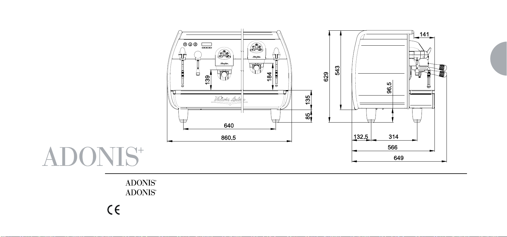
Modello:
Modello: 3 gruppi - Peso netto: 98 Kg - Peso Lordo: 108 Kg - Potenza termica: 5000 W - Capacità caldaia 17 lt - Volts 230-380V 50/60Hz
Il marchio di approvazione certifica che tutte le macchine sono state sottoposte ad accuratissimi collaudi e controlli
2 gruppi - Peso netto: 84 Kg - Peso Lordo: 90 Kg - Potenza termica: 4500 W - Capacità caldaia 14 lt - Volts 230-380V 50/60Hz
3
Page 6

IT
INDICE
CARATTERISTICHE TECNICHE ........................... 3
1. NOTE GENERALI ALLA CONSEGNA ...................5
1.1 PRESCRIZIONI DI SICUREZZA ............................................................5
2. DESCRIZIONE ....................................................... 9
2.1 LISTA ACCESSORI ............................................................................10
3. TRASPORTO E MOVIMENTAZIONE .................. 11
3.1 IDENTIFICAZIONE MACCHINA .......................................................... 11
6. UTILIZZO .............................................................. 18
6.1 PROCEDURA DI PRIMA INSTALLAZIONE O
DOPO MANUTENZIONE CALDAIE (versione T3) ................................18
6.2 ACCENSIONE DELLA MACCHINA .....................................................18
6.3 ACCENSIONE LED ............................................................................20
6.4 LEGENDA TASTI (Configurazione Selezioni) ........................................ 20
6.5 REGOLAZIONE FLUSSO DEL VAPORE .............................................21
6.6 REGOLAZIONE LANCIA TURBOCREAM (Ove Installata) ....................21
6.7 REGOLAZIONE LANCIA AUTOSTEAM (Ove Installata) ........................ 22
7. PROGRAMMAZIONE ........................................... 23
7.1 LEGENDA..........................................................................................23
7.2 VISUALIZZAZIONE (Mod. UTENTE) .............................................................23
7.3 VISUALIZZAZIONE (Mod. TECNICO) ...........................................................25
4. INSTALLAZIONE E OPERAZIONI
PRELIMINARI ....................................................... 12
5. REGOLAZIONI DEL TECNICO
QUALIFICATO ...................................................... 14
5.1 RIEMPIMENTO MANUALE CALDAIA .................................................14
5.2 REGOLAZIONE PRESSOSTATO / POMPA ......................................... 15
5.3 REGOLAZIONE ECONOMIZZATORE ACQUA CALDA ........................16
5.4 SOSTITUZIONE BATTERIA OROLOGIO .....................................................17
8. PULIZIA E MANUTENZIONE ............................... 41
8.1 ARRESTO .........................................................................................41
8.2 PULIZIA DELLA CARROZZERIA ......................................................... 41
8.3 PULIZIA DELLE DOCCETTE INOX ..................................................... 41
8.4 PULIZIA DEL GRUPPO CON L'AUSILIO DEL FILTRO CIECO .............. 42
8.5 PULIZIA DEI FILTRI E PORTAFILTRI ...................................................42
9. MESSAGGI FUNZIONI MACCHINA .................... 43
4
Page 7

1. NOTE GENERALI ALLA CONSEGNA
1.1 PRESCRIZIONI DI SICUREZZA
➊
Il presente libretto costituisce parte integrante ed
essenziale del prodotto e dovrà essere consegnato
all’utilizzatore. Leggere attentamente le avvertenze
contenute nel presente libretto in quanto forniscono
importanti indicazioni riguardanti la sicurezza di installazione, d’uso e manutenzione. Conservare con cura
questo libretto per ogni ulteriore consultazione.
PERICOLO DI INQUINAMENTO
➋
Dopo aver tolto l’imballaggio assicurarsi dell’integrità dell’apparecchio. In caso di dubbio non utilizzare
l’apparecchio e rivolgersi a personale professionalmente qualificato. Gli elementi dell’imballaggio non devono
essere lasciati alla portata dei bambini in quanto potenziali fonti di pericolo, né essere dispersi nell’ambiente.
➌
Prima di collegare l’apparecchio accertarsi che
i dati di targa siano rispondenti a quelli della rete
di distribuzione elettrica. L’installazione deve essere
effettuata in ottemperanza alle norme vigenti nel paese
dove la macchina viene instal lata, secondo le istruzioni
del costruttore e da personale qualificato.
Il costruttore non può essere considerato responsabile
per eventuali danni causati dalla mancanza di messa a
terra dell’impianto. Per la sicurezza elettrica di questo
apparecchio è obbligatorio predisporre l’impianto di
messa a terra, rivolgendosi ad un elettricista munito di
idoneità tecnica certificata, che dovrà verificare che la
portata elettrica dell’impianto sia adeguata alla potenza
massima dell’apparecchio indicata in targa.
In particolare dovrà anche accertare che la sezione
dei cavi dell’impianto sia idonea alla potenza assorbita
dall’apparecchio.
multiple e prolunghe.
Qualora il loro uso si rendesse indispensabile è necessario chiamare un elettricista munito di patentino.
È vietato l’uso di adattatori, prese
➍
Durante l'installazione del dispositivo devono essere utilizzati i componenti e i materiali in dotazione al
dispositivo stesso. Qualora fosse necessario l'utilizzo
di altra componentistica, l'installatore deve verificare
l'idoneità dello stesso ad essere utilizzato a contatto
con l'acqua per consumo umano.
➍
bis L'installatore deve eseguire i collegamenti
idraulici rispettando le norme di igene e sicurezza
idraulica di tutela ambientale vigenti nel luogo di installazione. Quindi per l’impianto idraulico rivolgersi ad un
tecnico autorizzato.
❺
L'alimentazione del dispositivo deve essere effettuata con acqua idonea al consumo umano conforme
alle disposizioni vigenti nel luogo di installazione.
L'installatore deve acquisire dal proprietario/gestore
dell'impianto conferma che l'acqua rispetti i requisiti
sopra indicati.
IT
5
Page 8

IT
❻
Questo apparecchio dovrà essere destinato solo
all’uso descritto in questo manuale. Il costruttore non
può essere considerato responsabile per eventuali
danni causati da usi impropri, erronei ed irragionevoli.
AVVERTENZA
Prima di utilizzare la macchina leggere interamente il
manuale d’uso o quantomeno le prescrizioni di sicurezza e la messa a punto.
❼
L’apparecchio non è idoneo per l’utilizzo da parte
dei bambini, persone con ridotte capacità fisiche, sensoriali o mentali, o carenti di conoscenze a meno che
non sia data supervisione o istruzione.
❽
Le temperature massime e minime di immagazzina-
mento devono essere comprese nel range [-5,+50]°C.
❽
bis
La temperatura di funzionamento deve essere
compresa nel range [+5, +35]°C.
❾
Al termine dell'installazione, il dispositivo viene attivato e portato fino alla condizione nominale di lavoro lasciandolo in condizioni di “pronto al funzionamento”.
Successivamente il dispositivo viene spento e tutto il circuito idraulico viene svuotato della prima acqua immessa in
modo da eliminare eventuali impurità iniziali.
In seguito il dispositivo viene nuovamente caricato e portato fino alle condizioni nominali di funzionamento.
Dopo il raggiungimento dello stato di “pronto al funzionamento” si effettuano le seguenti erogazioni:
- 100% del circuito caffè attraverso l'erogatore caffè (per
più erogatori si divida in uguale misura);
- 100% del circuito acqua calda attraverso l'erogatore
acqua (per più erogatori si divida in uguale misura);
- apertura di ciascuna uscita vapore per 1 minuto.
Al termine dell'installazione sarebbe buona regola stilare
un rapporto di quanto effettuato.
❿
L’uso di un qualsiasi apparecchio elettrico comporta
l’osservanza di alcune regole fondamentali. In particolare:
non toccare l’apparecchio con mani o piedi bagnati;
non usare l’apparecchio a piedi nudi;
non usare, prolunghe in locali adibiti a bagno o doccia;
non tirare il cavo di alimentazione, per scollegare
l’apparecchio dalla rete di alimentazione;
non lasciare esposto l’apparecchio ad agenti atmosfe-
rici (pioggia, sole, ecc.);
non permettere che l’apparecchio sia usato da bam-
bini, o da personale non autorizzato e che non abbia
letto e ben compreso questo manuale.
In fase di installazione la rete elettrica dovrà essere
predisposta con un sezionatore che sezioni ogni fase.
⓫
Il tecnico autorizzato deve, prima di effettuare qualsiasi operazione di manutenzione, staccare la spina
dopo aver spento l’interruttore della macchina.
⓫
bis Per le operazioni di pulizia portare la macchina
a stato energetico “O”, cioè “interruttore macchina
spento e spina staccata” ed attenersi esclusivamente
a quanto previsto nel presente libretto.
⓬
In caso di guasto o di cattivo funzionamento dell’apparecchio, spegnerlo. È severamente vietato intervenire.
6
Page 9
Rivolgersi esclusivamente a personale professionalmente
qualificato. L’eventuale riparazione dei prodotti dovrà
essere effettuata solamente dalla casa costruttrice o
da centro di assistenza autorizzato utilizzando esclusivamente ricambi originali. Il mancato rispetto di quanto
sopra può compromettere la sicurezza dell’apparecchio.
⓭
All’installazione, l’elettricista munito di patentino dovrà prevedere un interruttore unipolare come previsto dalle normative di sicurezza
vigenti con distanza di apertura dei contatti uguale o
superiore a 3 mm.
⓮
Per evitare surriscaldamenti pericolosi si raccomanda di svolgere per tutta la sua lunghezza il cavo
di alimentazione.
⓮
bis Il cavo di alimentazione di questo apparec-
chio non deve essere sostituito dall’utente. In caso
di danneggiamento, spegnere l’apparecchio e per la
sua sostituzione rivolgersi esclusivamente a personale
professionalmente qualificato.
⓯
Allorché si decida di non utilizzare più un apparecchio
di questo tipo si raccomanda di renderlo inoperante dopo
aver staccato la spina, tagliare il cavo di alimentazione.
ATTENZIONE PERICOLO DI INQUINAMENTO
Non disperdere la macchina nell’ambiente: per lo smaltimento rivolgersi ad un centro autorizzato o contattare
il costruttore che darà indicazioni in merito.
⓰
Per favorire l’areazione della macchina posizionarla
a cm 15 da muri da altre macchine.
ATTENZIONE PERICOLO DI USTIONE
⓱
Durante l’uso della lancia del vapore, prestare
molta attenzione e non mettere le mani sotto di esso e
non toccarla subito dopo l’uso.
⓲
Ricordare che prima di effettuare qualsiasi operazione di installazione, manutenzione, scarico, regolazione, l’operatore qualificato deve indossare i guanti da
lavoro e le scarpe antinfortunistiche.
⓳
Il massimo livello di disturbo sonoro emesso è
inferiore ai 70db.
⓴
Il tubo alla connessione idrica se sostituito non
deve essere più riutilizzato.
ATTENZIONE
INFORMAZIONE AGLI UTENTI
Ai sensi dell’ art. 13 del Decreto
Legislativo 25 luglio 2005, n. 151
“Attuazione delle Direttive 2002/95/
CE, 2002/96/CE e 2003/108/CE, relative alla riduzione dell’ uso di sostan-
ze pericolose nelle apparecchiature
elettriche ed elettroniche, nonché allo smaltimento
dei rifiuti”.
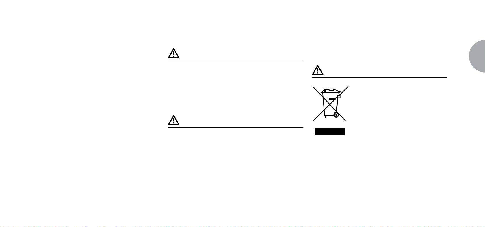
Il simbolo del cassonetto barrato riportato sull’apparecchiatura indica che il prodotto alla fine della propria
vita utile deve essere raccolto separatamente dagli altri
rifiuti. L’ utente dovrà, pertanto, conferire l’ apparec-
IT
7
Page 10

IT
chiatura giunta a fine vita agli idonei centri di raccolta
differenziata dei rifiuti elettronici ed elettrotecnici, oppure riconsegnarla al rivenditore al momento dell’acquisto
di una nuova apparecchiatura di tipo equivalente, in
ragione di uno a uno. L’adeguata raccolta differenziata
per l’ avvio successivo dell’ apparecchiatura dimessa
al riciclaggio,al trattamento e allo smaltimento ambientalmente compatibile contribuisce ad evitare possibili
effetti negativi sull’ ambiente e sulla salute e favorisce
il riciclo dei materiali di cui è composta l’ apparecchiatura. Lo smaltimento abusivo del prodotto da parte
dell’ utente comporta l’ applicazione delle sanzioni
amministrative di cui al D.Lgs.n.22/1997” (articolo 50 e
seguenti del D.Lgs.n.22/1997).
8
Page 11
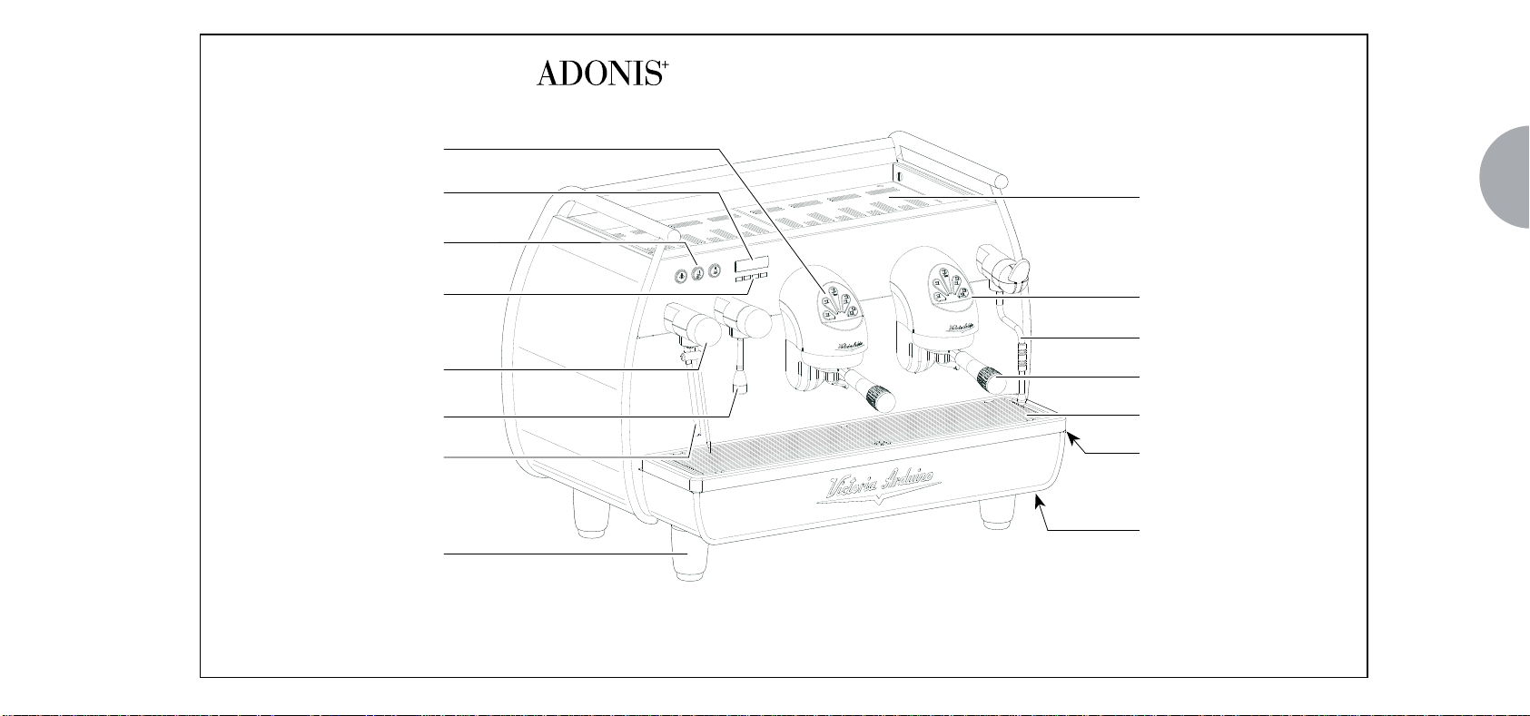
2. DESCRIZIONE
- DIGIT - T3
Pulsanti Gruppo Erogatore
Display LCD
Pulsanti Selezione
Acqua Calda / Vapore
Tasti Programmazione
Manopola Regolazione
Flusso Vapore
Lancia Acqua Calda
Lancia Autosteam
Piede Regolabile
IT
Scaldatazze Elettrico
Gruppo Erogazione
Lancia Vapore Manuale
Portafiltro
Griglia Poggiatazze
Piatto Raccogligocce
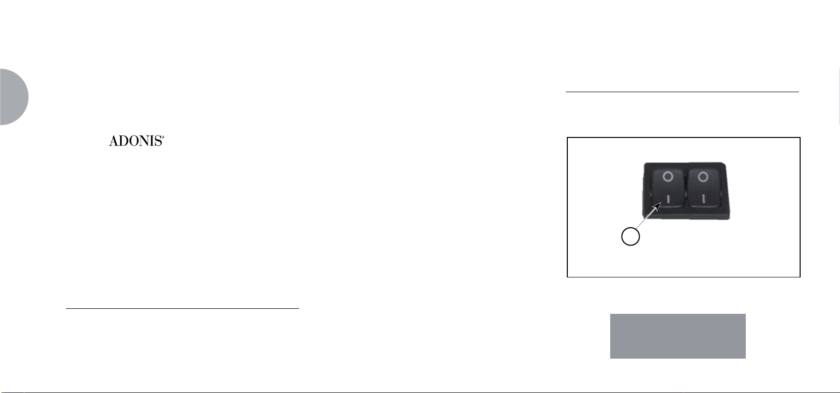
Interruttore Generale
Macchina
Fig. 1
9
Page 12
IT
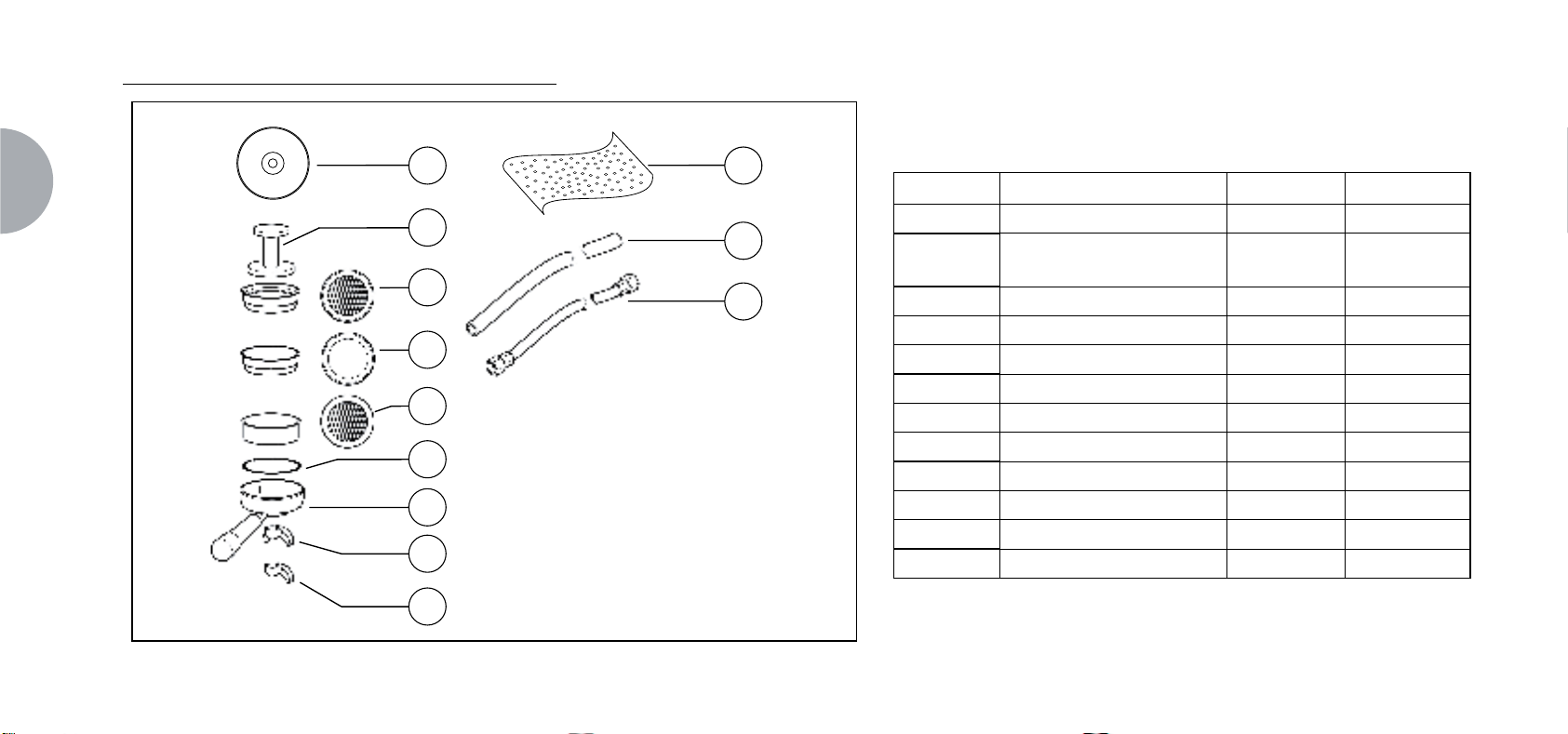
2.1 LISTA ACCESSORI
A12 A11
A10
A05
A06
A04
A07
A03
A08
A02
A01
CODICE DESCRIZIONE 2 GRUPPI 3 GRUPPI
A01 Tubo carico Ǫ” 11
A02
A03 Porta¿ltro 3 4
A04 Filtro doppio 2 3
A05 Filtro singolo 1 1
A06 Filtro cieco 1 1
A07 Molla 3 4
A08 Becco erogazione doppio 2 3
A09 Becco erogazione singolo 1 1
A10 Pressa caffè 1 1
A11
A12
Tubo scarico piano lavoro
Ø 25 mm - l. 150 cm
11
Panno in micro¿bra 1 1
DVD 1 1
10
A09
Fig. 2
Page 13
3. TRASPORTO E MOVIMENTAZIONE
3.1 IDENTIFICAZIONE MACCHINA
Per qualsiasi comunicazione con il costruttore Victoria
Arduino, citare sempre il numero di matricola della
macchina.
La macchina viene trasportata in pallett con più macchine
dentro scatoloni assicurati al pallett con delle centine.
Prima di procedere a qualsiasi operazione di trasporto o
movimentazione, l’operatore deve:
indossare guanti e scarpe antinfortunistici ed una tuta
con elastici alle estremità.
Il trasporto del pallett deve essere effettuato con un mezzo
di sollevamento adeguato (tipo muletto).
A TTENZIONE PERICOLO DI URTO O SCHIACCIAMENTO
L’operatore durante tutta la movimentazione, deve avere
l’attenzione che non ci siano persone, cose od oggetti
nell’area di operazione.
Sollevare lentamente il pallett a circa 30 cm da terra e
raggiungere la zona di carico. Dopo aver verificato che
non ci siano ostacoli, cose o persone, procedere al carico.
Una volta arrivati a destinazione, sempre con un mezzo
di sollevamento adeguato (es. muletto), dopo essersi
assicurati che non ci siano cose o persone nell’area di
scarico, portare il pallett a terra e movimentarlo a circa 30
cm da terra, fino all’area di immagazzinamento.
A TTENZIONE PERICOLO DI URTO O SCHIACCIAMENTO
Prima della seguente operazione verificare che il carico
sia a posto e che con il taglio delle centine non cada.
L’operatore con guanti e scarpe antinfortu nistiche, deve
procedere al taglio delle centine e allo stoccaggio del prodotto, in questa operazione consultare le caratteristiche
tecniche del prodotto per vedere il peso della macchina
da immagazzinare e potersi regolare di conseguenza.
ATTENZIONE PERICOLO DI INQUINAMENTO
Una volta liberata la macchina del pallett o del contenitore,
non disperderlo nell’ambiente, pericolo di inquinamento.
IT
11
Page 14
4. INSTALLAZIONE E OPERAZIONI PRELIMINARI
12
IT
Una volta rimosso l’imballo e aver verificato l’integrità
della macchina e degli accessori, procedere come
descritto di seguito:
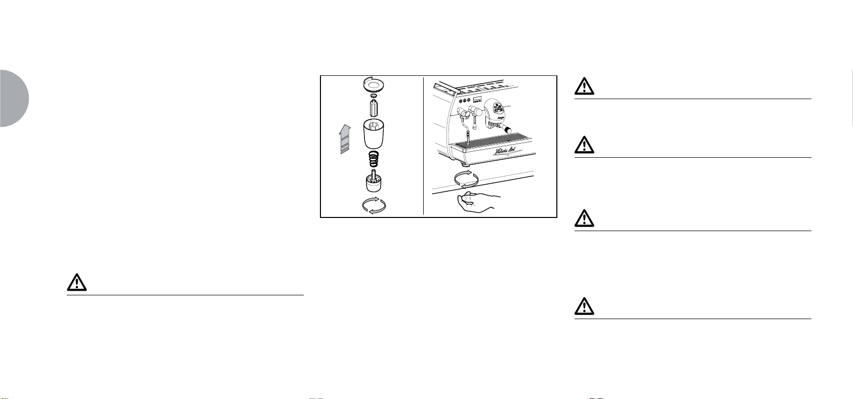
posizionare la macchina su un piano orizzontale;
assemblare i piedini di sostegno della macchina
inserendo l’inserto all’interno del guscio cilindrico
(vedi Fig. 3);
avvitare il piedino in gomma nella filettatura dell’in-
serto contenuto nel guscio (vedi Fig. 3);
avvitare tutto il gruppo assemblato nelle apposite
sedi di alloggiamento dei piedini della macchina;
mettere in piano la macchina agendo sui piedini di
regolazione;
NOTA BENE
La scanalatura del guscio deve essere rivolta verso
l’alto, come indicato nella figura successiva.
Fig. 3
In fase preliminare, dopo la messa in piano della macchina, si consiglia di installare un addolcitore (1), all’uscita
della rete idrica, e di seguito un filtro a maglia (2).
Questo non permette alle impurità, come sabbia, particelle di calcare in sospensione, ruggine ecc., di danneggiare
le delicate superfici in grafite, garantendo una buona
durata della macchina.
Dopo queste operazioni, provvedere ai collegamenti
idraulici come illustrato nella seguente figura.
ATTENZIONE
La pressione della rete idrica raccomandata è [2,3] bar .
ATTENZIONE
Evitare strozzature nei tubi di collegamento.
Verificare inoltre che lo scarico (3) sia in grado di eliminare gli scarti.
NOTA BENE
All'inizio della attività giornaliera e comunque nel
caso in cui vi siano pause maggiori di 8 ore bisogna
procedere ad effettuare il ricambio del 100% dell'acqua
contenuta nei circuiti utilizzando gli erogatori preposti.
NOTA BENE
In caso di esercizi in cui il servizio è continuativo effettuare i ricambi di sopra descritti almeno con frequenza
settimanale.
Page 15

2
1
3
Fig. 4
LEGENDA
① Addolcitore
② Filtro a maglia
③ Scarico Ø 50 mm
NOTA BENE
Per un buon funzionamento della macchina occorre
che la pressione di rete non superi i 4 bar.
In caso contrario, installare un riduttore di pressione a
monte dell’addolcitore; il tubo in entrata dell’acqua deve
avere un diametro interno non inferiore ai 6 mm (Ǫ”).
ATTENZIONE PERICOLO DI SCOSSA ELETTRICA
La macchina deve essere sempre protetta con un interruttore automatico onnipolare di adeguata potenza con
distanza di apertura dei contatti uguale o superiore a 3
mm. La Nuova Simonelli non risponde di alcun danno
a cose o persone derivante dalla mancata osservanza
delle vigenti norme di sicurezza.
Prima di allacciare la macchina a una rete elettrica verificare che il voltaggio indicato sulla targhetta dati della macchina corrisponda a quello della rete. In caso contrario,
effettuare i successivi collegamenti sulla base della linea
elettrica a disposizione, come illustrato successivamente:
per voltaggio V 380 / 3 fasi + Neutro:
1234
5
per voltaggio V 230 / monofase:
IT
1234
5
Fig. 6
LEGENDA
① Nero
② Grigio
③ Marrone
④ Blu
⑤ Gialloverde
Fig. 5
13
Page 16

5. REGOLAZIONI DEL TECNICO QUALIFICATO
14
IT
5.1 RIEMPIMENTO MANUALE
CALDAIA
NOTA BENE
Operazione da eseguire a macchina spenta.
Tutti i modelli sono muniti di sonda di livello,
per mantenere costante il livello di acqua all’interno della
caldaia.
E’ buona norma, al primo avviamento della macchina,
riempire manualmente la caldaia per evitare che la resistenza elettrica si danneggi e che inserisca la protezione
elettronica.
Se questo dovesse accadere, è sufficiente spegnere la
macchina e riaccenderla, per completarne il caricamento
(vedi capitolo “MESSAGGI FUNZIONE MACCHINA -
ERRORE LIVELLO”).
Per effettuare il primo riempimento manuale, agire
come descritto di seguito:
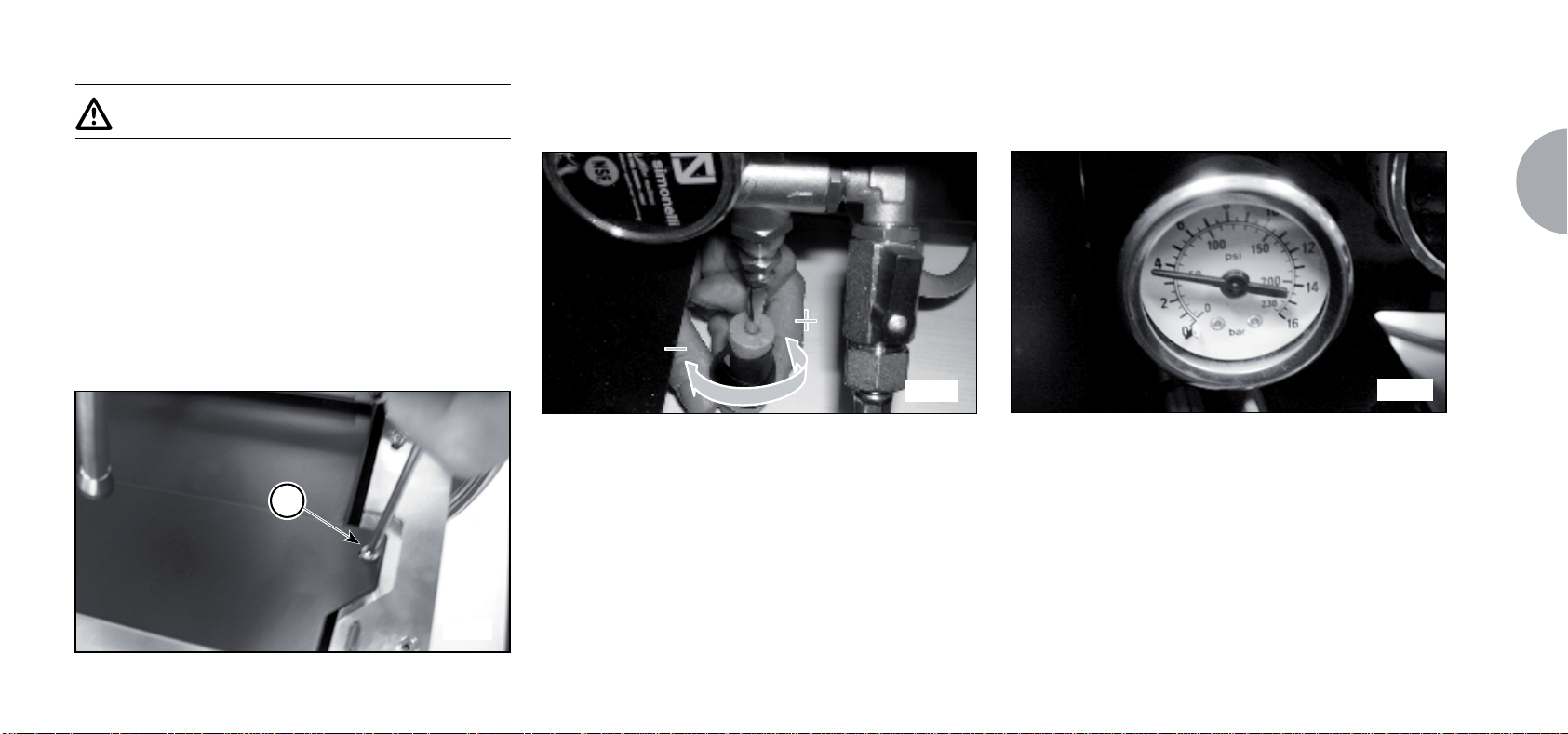
rimuovere la griglia e il piatto raccogligocce;
togliere la protezione in lamiera svitando le due viti
laterali "A" come illustrato nella seguente figura;
A
Fig. 7
agire sul rubinetto livello manuale “A”, per permet-
tere l’ingresso dell’acqua nella caldaia;
dopo circa 45 secondi chiudere il rubinetto ”A”
come illustrato nella seguente figura;
A
Fig. 8
accendere la macchina
(vedi capitolo “ACCENSIONE
MACCHINA”).
Page 17
5.2 REGOLAZIONE POMPA
NOTA BENE
Operazione eseguibile anche a macchina accesa.
Per modificare la pressione di esercizio della caldaia,
quindi la temperatura dell’acqua, in funzione delle
varie esigenze o delle caratteristiche del caffè utilizzato, agire come descritto di seguito:
rimuovere la griglia e il piatto raccogligocce;
togliere la protezione in lamiera svitando le due viti
laterali "A" come illustrato nella seguente figura;
Agire sulla vite di regolazione della pompa per
AUMENTARE (senso orario) oppure DIMINUIRE
(senso antiorario) la pressione;
Fig. 10
La pressione impostata della pompa viene visualizzata sul manometro, alloggiato all'interno della
macchina (vedi Fig. 11);
Fig. 11
IT
Valore consigliato: 9 bar
Al termine delle regolazioni, riposizionare la protezione in lamiera nell’apposito alloggiamento e fissarla
A
con le due viti laterali; riposizionare il piatto raccogligocce e la griglia del piano di lavoro.
Fig. 9
15
Page 18
IT
5.3 REGOLAZIONE ECONOMIZZATORE
Per accedere all'economizzatore smontare la por-
ACQUA CALDA
NOTA BENE
Operazione eseguibile anche a macchina accesa.
Tutti i modelli sono equipaggiati di un miscelatore di acqua calda, il quale permette di regolare la temperatura di uscita dell’acqua e di ottimizzare il rendimento
del sistema.
Per regolare l’economizzatore acqua calda, agire sul
pomello di registro.
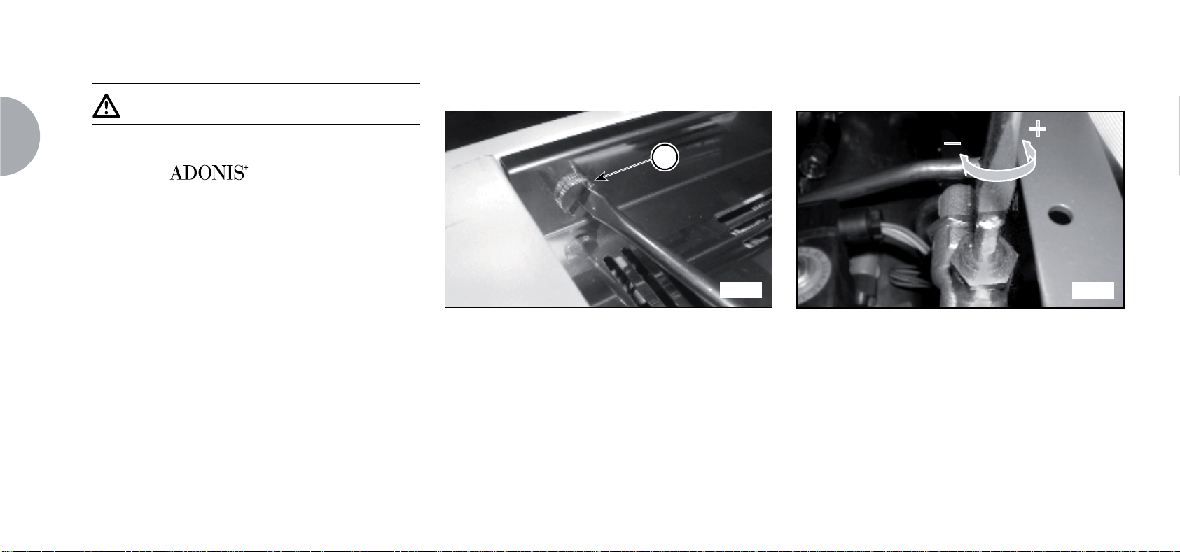
L'economizzatore dell'acqua calda è alloggiato
all'interno della macchina.
zione scaldatazze sinistro svitando le due viti "D"
come illustrato nella seguente figura.
D
Fig. 12
ruotare il pomello di registro in senso ANTIORARIO /
ORARIO per AUMENTARE / DIMINUIRE la temperatura dell’acqua calda;
Fig. 13
al termine dell’operazione rimontare il pannello
protettivo con le apposite viti.
16
Page 19

5.4 SOSTITUZIONE BATTERIA
OROLOGIO
La centralina elettronica è provvista di una batteria al litio
per l’alimentazione dell’orologio con autonomia di circa tre
anni, dopodichè può rendersi necessaria la sostituzione.
In caso di stop prolungato della macchina, l’orologio può
essere bloccato con la seguente procedura:
con la macchina spenta, il display visualizza:
OFF
mantenere premuto il tasto ENTER per 5 sec.; il
display visualizza:
STOP OROLOGIO
ATTENZIONE
La sostituzione della batteria al litio deve essere eseguita
SOLO dal Tecnico Specializzato.
La Nuova Simonelli non risponde di alcun danno a cose
o persone, derivanti da una mancata osservanza delle
prescrizioni di sicurezza, descritte in questo manuale.
IT
L’orologio si riavvierà appena la macchina sarà collegata
all’alimentazione elettrica.
17
Page 20
6. UTILIZZO
18
IT
L’operatore deve prima di iniziare la lavorazione, accertarsi di aver letto e ben compreso le prescrizioni di sicurezza
di questo manuale.
Il modello
zazione T e una chiave tecnico U. Con la chiave visualizzazione T si può accedere alle normali funzioni di
lavoro e possono essere visualizzati ma non modificati i
menù della programmazione (Cap. 7).
La chiave tecnico U permette di accedere a tutte le
funzioni e di modificare i parametri dei menu di programmazione.
è dotato di una chiave visualiz-
6.1 PROCEDURA DI PRIMA INSTALLAZIONE O DOPO MANUTENZIONE CALDAIE (VERSIONE T3)
In fase di prima installazione della macchina o dopo la
manutenzione di una delle caldaie, accesa la macchina
dall’interruttore generale posto in basso a destra, procedere come segue:
① Se a display viene visualizzato “ OFF - OROLOGIO
DISABILITATO “ procedere come al passo 3.
② Se a display viene visualizzato “OFF “ premere il
tasto
ENTER fino a quando non viene visualizzato
a display "OFF - OROLOGIO DISABILITATO" e
quindi procedere come al passo 3.
③ Accendere la macchina premendo il tasto
ed automaticamente dopo l’accensione uscirà
acqua dai gruppi per 45sec al fine di assicurare il
corretto riempimento delle caldaie caffè.
Questo ciclo non può e non deve essere interrotto.
Nel caso in cui sia interrotto per mancanza di
elettricità o spegnimento accidentale della macchina dall’interruttore generale alla successiva
riaccensione la macchina riavvierà d nuovo il ciclo
per altri 45 sec.
RESET
6.2 ACCENSIONE DELLA MACCHINA
Chiudere il sezionatore e posizionare l’interruttore
generale "A" in posizione “I”.
A
Fig. 14
Sul display, non illuminato, compare la scritta:
OFF
Page 21
NOTA BENE
La macchina non è operativa, in quanto l’interruttore
generale permette solo l’alimentazione della scheda
elettronica.
ATTENZIONE
In caso di manutenzione alla scheda elettronica, spegnere la macchina tramite l’interruttore generale esterno o
scollegare il cavo di alimentazione.
ACCENSIONE / SPEGNIMENTO MANUALE
On - Off Automatico NON PROGRAMMATO
ACCENSIONE
Premere il tasto RESET per 2 sec., il cicalino emette un
bip, il display si illumina indicando la release della Eprom
per circa 1 secondo.
La centralina effettua l’autodiagnosi delle funzioni, tutti i
tasti di selezione si illuminano.
Terminata la diagnosi, sul display compare la scritta:
RISCALDAMENTO
con giorno e ora. Raggiunta la temperatura di 110°C, la
scritta riscaldamento scompare, sostituita da:
NOTA BENE
Tutti i tasti di selezione sono abilitati sin dalla fine
della diagnosi.
IT
ATTENZIONE
Nel caso in cui l’autodiagnosi indichi anomalie o guasti,
chiamare il centro di assistenza, l’operatore NON DEVE
intervenire.
SPEGNIMENTO
Premere il tasto RESET per 2 secondi la macchina si
spegne e sul display è indicato:
OFF
On - Off Automatico PROGRAMMATO
MACCHINA PRONTA
La macchina si ACCENDERA’ al primo orario di accensione programmato (vedi capitolo "PROGRAMMAZIONE" e
paragrafo "PROGRAMMAZIONE ON - OFF").
19
Page 22
La centralina effettua l’autodiagnosi delle funzioni, tutti i
tasti di selezione si illuminano.
Terminata la diagnosi, sul display compare la scritta:
La macchina si SPEGNERA’ al primo orario di spegnimento programmato (vedi capitolo "PROGRAMMAZIONE" e
paragrafo "PROGRAMMAZIONE ON - OFF").
6.4 LEGENDA TASTI
Configurazione selezioni
20
IT
RISCALDAMENTO
con giorno e ora. Raggiunta la temperatura di 110°C, la
scritta riscaldamento scompare, sostituita da:
MACCHINA PRONTA
NOTA BENE
Tutti i tasti di selezione sono abilitati sin dalla fine
della diagnosi.
ATTENZIONE
Nel caso in cui l’autodiagnosi indichi anomalie o guasti,
chiamare il centro di assistenza, l’operatore NON DEVE
intervenire.
NOTA BENE
La macchina può essere accesa o spenta manualmente come indicato nel paragrafo precedente.
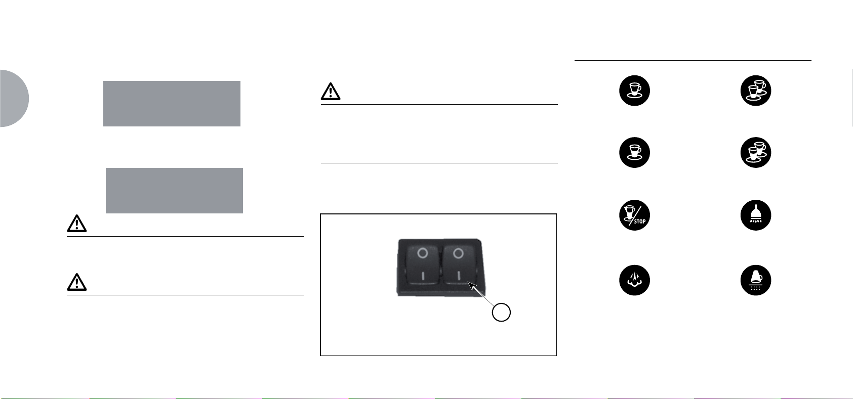
6.3 ACCENSIONE LED
Chiudere il sezionatore e posizionare l’interruttore
generale "B" in posizione “I”.
B
Fig. 15
1 Caffè corto 2 Caffè corto
1 Caffè lungo 2 Caffè lungo
Continuo Acqua calda
Vapore Scaldatazze
Page 23
6.5 REGOLAZIONE FLUSSO DEL
VAPORE
Per aumentare/diminuire il flusso del vapore iniettato
nel latte agire sulla leva come illustrato nella figura
seguente.
Fig. 16
NOTA BENE
L'utilizzo della lancia vapore deve essere sempre
preceduta dall'operazione di spurgo della condensa
per almeno 2 secondi o seguendo le istruzioni del
costruttore.
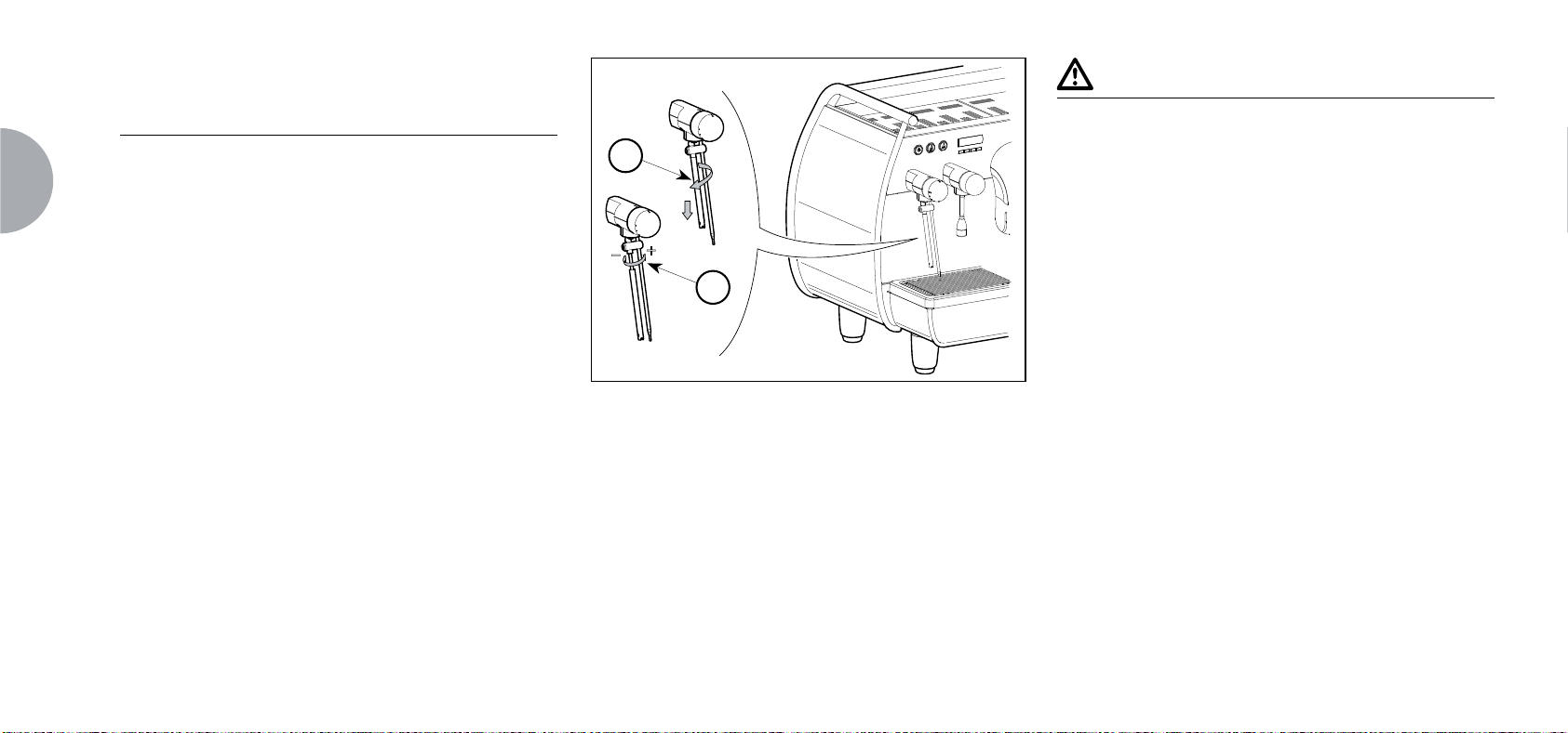
6.6 REGOLAZIONE LANCIA
TURBOCREAM
(Ove Installata)
Per aumentare/diminuire la quantità di aria iniettata nel
latte tramite lancia TurboCream (ed quindi aumentare/
diminuire la percentuale di crema nel latte montato)
procedere
② Per aumentare/diminuire la quantità di aria avvita-
re/svitare la cannula in teflon (2) come illustrato in
Fig. 17.B.
③ Avvitare di nuovo la cannula in acciaio inox.
come illustrato in Fig. 17:
Fig. 17.A
1
2
Fig. 17.B
NOTA BENE
Fig. 17
Riducendo o aumentando la lunghezza (avvitando o
svitandola) della cannula in teflon di qualche frazione
di mm o mm si ottengono sensibili differenze nel livello
di crema del latte montato.
IT
21
Page 24
IT
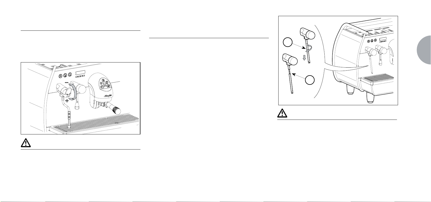
6.7 REGOLAZIONE LANCIA
AUTOSTEAM
(Ove Installata)
Per aumentare/diminuire la quantità di aria iniettata nel
latte tramite lancia AutoSteam (ed quindi aumentare/
diminuire la percentuale di crema nel latte montato)
procedere come illustrato in Fig. 18:
① Svitare la cannula in acciaio inox (1) come illustrati
in Fig. 18.A.
② Per aumentare/diminuire la quantità di aria avvita-
re/svitare la cannula in teflon (2) come illustrato in
Fig. 18.B.
③ Avvitare di nuovo la cannula in acciaio inox.
Fig. 18.A
1
2
Fig. 18.B
Fig. 18
④ Per quanto riguarda l'impostazione della tempera-
tura si rimanda al relativo paragrafo della programmazione.
NOTA BENE
Riducendo o aumentando la lunghezza (avvitando o
svitandola) della cannula in teflon di qualche frazione
di mm o mm si ottengono sensibili differenze nel livello
di crema del latte montato.
22
Page 25
7. PROGRAMMAZIONE
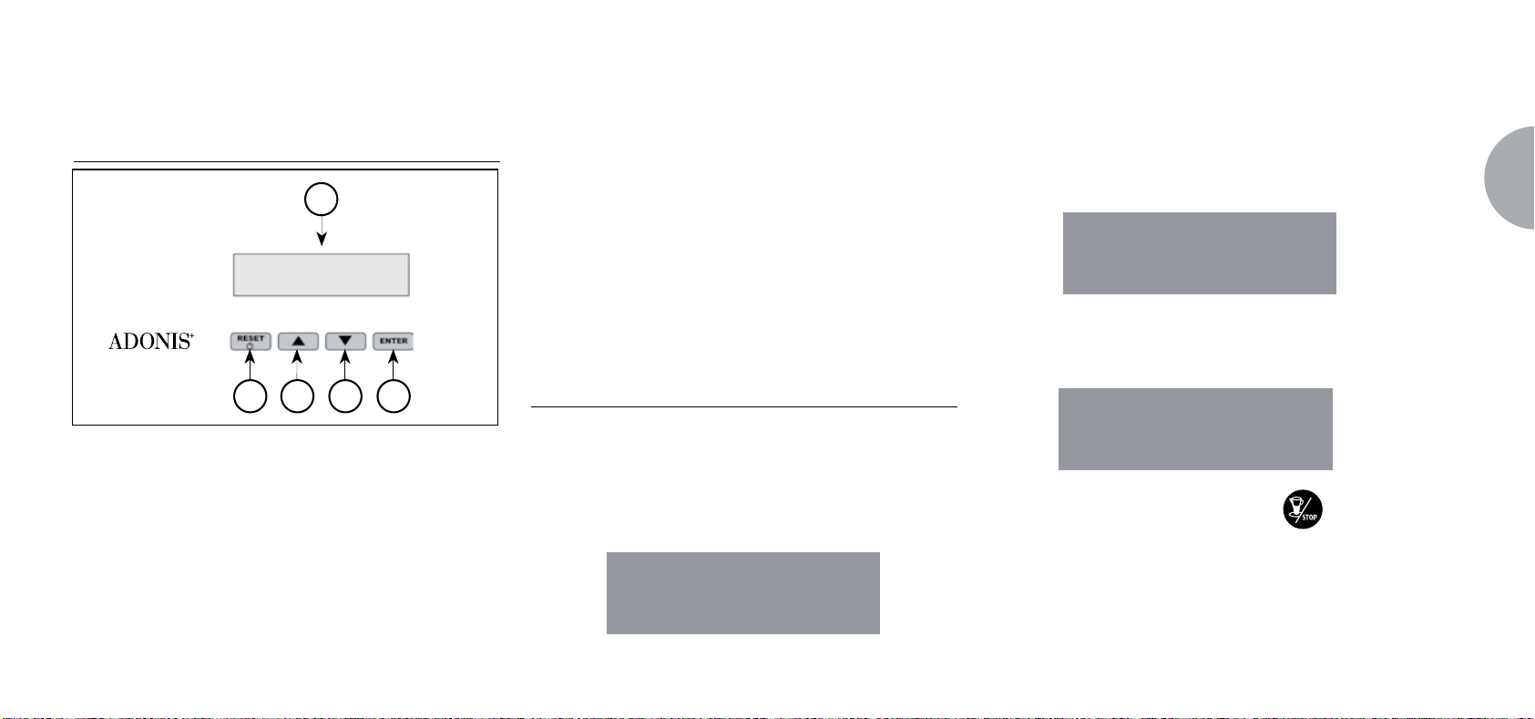
7.1 LEGENDA
1
2 3 4 5
① Display LCD.
②
Ta st o RESET: per confermare e ritornare
Fig. 19
allo step precedente.
③ Ta st o CURSORI: scorrimento dei menù ed
④ incremento e decremento
valori.
⑤ Ta st o ENTER: per accedere all'interno del
menù.
LIST A FUNZIONI VISUALIZZABILI (Mod. UTENTE)
CICL.AUT.PULIZIA
DOSI
CONT.EROGAZIONI
TOTALE
TOTALE MACCHINA
CONTEGGIO LAVAGGI
7.2 VISUALIZZAZIONE (Mod. UTENTE)
Per entrare nell’ambiente di visualizzazione in modalità
utente premere il tasto
dere il primo segnale acustico.
La macchina visualizzerà:
ENTER per 8 secondi e atten-
CICL.AUT.PULIZIA
CICLO AUTOMATICO DI PULIZIA
Sul display è visualizzato:
CICL.AUT.PULIZIA
Premere ENTER e sul display verrà visualizzato:
CICL.AUT.PULIZIA
SELEZIONA
Il tasto centrale di ogni gruppo
a lampeggiare. Inserire il filtro cieco (Fig. 2 A06)
nel portafiltro, aggiungere mezza dose di pulicaff
e agganciare il portafiltro al gruppo sul quale si
vuole procedere con il lavaggio automatico. E’
comincerà
IT
23
Page 26

IT
possibile effettuare il lavaggio anche in più gruppi
contemporaneamente.
Premere il tasto
automatico sul gruppo. Sul display comparirà:
per avviare il ciclo di pulizia
CICL.AUT.PULIZIA
¡ L
dove 1L indica che nel 1° gruppo è stato attivato il
ciclo di lavaggio. Terminato il ciclo di 15 erogazioni
da 5 secondi l’una, con una pausa fra le erogazioni di 10 secondi, il tasto
nato torna a lampeggiare e sul display comparirà:
del gruppo selezio-
DOSI
Sul display è visualizzato:
DOSI
Premere il tasto ENTER e tutti i tasti dose, acqua
calda e vapore lampeggeranno.
Premendo uno dei tasti lampeggianti a display verrà
visualizzato il corrispondente valore programmato.
Premere il tasto
dente.
Premere il tasto
zione.
V
per tornare alla funzione prece-
RESET per uscire dalla visualizza-
calda e vapore lampeggeranno.
Premendo uno dei tasti lampeggianti a display verrà
visualizzato il corrispondente contatore.
Premere il tasto
dente.
Premere il tasto
zione.
TOTALE
Sul display è visualizzato:
V
per tornare alla funzione prece-
RESET per uscire dalla visualizza-
TOTALE
24
RISCIACQUARE
Premere il tasto RESET per visualizzare la funzio-
ne successiva o per uscire dalla visualizzazione.
CONTEGGIO EROGAZIONI
Sul display è visualizzato:
CONT. EROGAZIONI
Premere il tasto ENTER e tutti i tasti dose, acqua
Il tasto caffè corto
gerà e premendolo potrà essere visualizzato il numero di caffè eseguiti con quel dato gruppo.
Premere i tasti WV per visualizzare le altre funzioni.
Premere il tasto
TOTALE MACCHINA
Sul display è visualizzato:
RESET
di ciascun gruppo lampeg-
per uscire dalla visualizzazione
.
Page 27

TOTALE MACCHINA
EROGAZ. xxx
Premere i tasti WV per visualizzare le altre funzioni.
Premere il tasto
CONTEGGIO LAVAGGI
Sul display è visualizzato:
RESET
per uscire dalla visualizzazione
CONTAT. LAVAGGI
Il tasto un caffè lungo di ciascun gruppo lampeggerà e premendolo potrà essere visualizzato il numero di cicli di lavaggio eseguiti per quel dato gruppo.
Premere i tasti WV per visualizzare le altre funzioni.
Premere il tasto
RESET
per uscire dalla visualizzazione
PROGRAM. DOSI
CONT. EROGAZIONI
GRUPPI A TTIVI *
PROGRAMM. ON/OFF
RISP. ENERGETICO
.
SETPOINT TEMPERATURA (E OFFSET) *
PRO. SCALDATAZZE
DATA/ORA
IMP. DISPLAY (E TEMPO DI EROGAZIONE) *
EROGAZIONE IN LAVAGGIO
TEMPO EROGAZIONE °
SETPOINT PRESS.
STORICO ALLARMI
MANUTENZIONE
ALLARME LAVAGGIO
LINGUA
TEMPERATURA
.
REG. LUMINOSITA’
NON qualificati o di altre persone potrebbe invalidare la garanzia.
* Solo versione T3
° Solo versione Digit
7.3 PROGRAMMAZIONE (Mod. TECNICO)
Per entrare nell’ambiente di visualizzazione in modalità
tecnico premere il tasto
dere il secondo segnale acustico. Il display visualizzerà:
ENTER per 10 secondi e atten-
CICL.AUT.PULIZIA
e successivamente:
PROGRAM. DOSI
IT
LISTA FUNZIONI PROGRAMMABILI (Mod. Tecnico)
CICL. AUT. PULIZIA
Operazione eseguibile SOLO da Tecnico
Specializzato. La regolazione da parte di Tecnici
25
Page 28

IT
CICLO AUTOMATICO DI PULIZIA
Sul display è visualizzato:
CICL.AUT.PULIZIA
Premere ENTER e sul display verrà visualizzato:
CICL.AUT.PULIZIA
SELEZIONA
Il tasto centrale di ogni gruppo
a lampeggiare. Inserire il filtro cieco (Fig. 2 A06)
nel portafiltro, aggiungere mezza dose di pulicaff
e agganciare il portafiltro al gruppo sul quale si
vuole procedere con il lavaggio automatico. E’
possibile effettuare il lavaggio anche in più gruppi
contemporaneamente.
Premere il tasto
automatico sul gruppo. Sul display comparirà:
per avviare il ciclo di pulizia
comincerà
CICL.AUT.PULIZIA
¡ L
dove 1L indica che nel 1° gruppo è stato attivato il
ciclo di lavaggio. Terminato il ciclo di 15 erogazioni
da 5 secondi l’una, con una pausa fra le erogazioni
di 10 secondi, il tasto
torna a lampeggiare e sul display comparirà:
del gruppo selezio
nato
RISCIACQUARE
Svuotare il filtro ceco da eventuali residui di pulicaff
e premere il tasto
quo nel gruppo o nei gruppi in cui è stato eseguito
il lavaggio. Nel display la lettere R rimane fissa cosi
come il tasto
del gruppo o dei gruppi selezionati, nel display com-
pare la scritta:
per avviare il ciclo di risciac-
. Terminato il ciclo di risciacquo
MACCHINA PRONTA
Nel caso in cui sia stato selezionato nella funzione
"EROGAZIONE IN LAVAGGIO" ATTIVA (vedi funzione), dopo aver selezionato i gruppi da pulire, premendo il tasto ENTER, si può uscire dal lavaggio
ed avere a disposizione i gruppi non selezionati per
erogare il caffè. Se si sceglie di uscire dal lavaggio,
per avere a disposizione i gruppi non in lavaggio per
eventuali erogazioni, il ciclo di pulizia verrà indicato
nella riga inferiore o in quella superiore a seconda
della scelta effettuata nel menù “TEMPO DI EROGAZIONE”. Nel caso in cui i tempi di erogazione
siano disattivati, il processo di pulizia verrà visualizzato sulla riga inferiore. Durante un ciclo di lavaggio
automatico fuori dal menù (quindi con erogazione
abilitata), non è possibile entrare nel menù di impostazione e spegnere la macchina, sia in manuale
che in automatico.
26
Page 29

PROGRAMMAZIONE DOSI
Sul display è visualizzato:
PROGRAM.DOSI
Premendo il tasto ENTER, il display visualizzerà:
PROGRAM.DOSI
SELEZIONA
Tutti i tasti programmabili cominceranno a lampeg-
giare.
Premere il tasto caffè da programmare, il display
visualizza:
VOLUME C.C:
Seguita dal valore già programmato dalla casa co-
struttrice.
Variare la dose, agendo con i pulsanti WV.
Premendo il tasto caffè da programmare, inizierà
l’erogazione (nel frattempo tutti gli altri tasti si spegneranno).
Una volta raggiunta la dose desiderata premere il
tasto caffè continuo
Sul display verrà visualizzato il nuovo valore che
sarà ancora possibile modificare con i tasti WV.
Premere il tasto ENTER per confermare la dose
programmata.
Premere il tasto RESET per annullare la program-
mazione.
Il tasto caffè programmato si spegne.
Acqua calda
Premere il pulsante
so si illumini. Sul display comparirà la scritta:
per arrestare l'erogazione.
e assicurarsi che lo stes-
PROGRAM. DOSI
SEC. ACQ. X.X
Il valore X.X è quello impostato.
Premere i tasti WVper variare il tempo di fuoriu-
scita dell’acqua calda da versare.
Se si intende fare un nuovo campionamento preme-
re nuovamente il pulsante
Inizia l’erogazione. Quando la dose desiderata è
raggiunta premere di nuovo il pulsante
Sul display viene visualizzato il nuovo valore da noi impostato ancora modificabile selezionando i tasti
Premere il tasto ENTER o passare ad una succes-
siva selezione per concludere l’operazione.
Premere il tasto RESET per annullare la program-
mazione.
Il pulsante
Vapore temporizzato/temperatura
Premere il pulsante
so si illumini.
Nelle versioni con sonda di temperatura (optional)
la centralina riconosce automaticamente la presen-
si spegne.
.
.
WV.
e assicurarsi che lo stes-
IT
27
Page 30
IT
za della sonda e sul display comparirà la scritta:
PROGRAM. DOSI
TEMP. VAP. °C
seguita dal valore già impostato dalla casa costrut-
trice.
Premere i tasti
deve raggiungere la bevanda da riscaldare. Raggiunta tale temperatura si fermerà automaticamente l’erogazione del vapore.
Nella versione standard (senza sonda di tempera-
tura) premendo il tasto
la scritta:
WV
per variare la temperatura che
sul display comparirà
PROGRAM. DOSI
SEC.VAP.
seguita dal valore già impostato dalla casa costrut-
trice. Premere con i tasti
di fuoriuscita del vapore da erogare.
Se si intende fare un nuovo campionamento preme-
WV
per variare il tempo
re nuovamente il pulsante
Inizia l’erogazione. Quando la dose desiderata è
raggiunta premere di nuovo il pulsante
Sul display viene visualizzato il nuovo valore da noi
impostato ancora modificabile selezionando i tasti
WV
.
Premere il tasto ENTER o passare a una successi-
va selezione per concludere l’operazione.
Premere il tasto RESET per annullare la program-
mazione.
Il pulsante
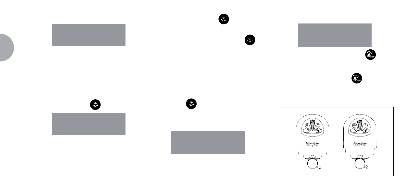
TRASFERIMENTO DOSI
Quando il display visualizza:
si spegne.
.
.
PROGRAM.
DOSI SELEZIONA
premendo il tasto Wsi ha la possibilità di trasferire
il valore delle dosi programmate agli altri gruppi.
Sul display verrà visualizzato:
TRASFERIME. DOSI
SELEZIONA GRUPPI
a questo punto i tasti caffè continuo
condo, terzo e quarto gruppo lampeggeranno come
in Fig. 20.
Selezionando il tasto continuo
(il tasto da lampeggiante diventa a luce fissa), si
trasferiscono i valori programmati del primo gruppo
agli altri gruppi.
uno alla volta
del se-
Fig. 20
28
Page 31

Premere il tasto ENTER per confermare.
A questo punto sul display viene visualizzato:
PROGRAM.
DOSI SELEZIONA
Premere il tasto RESET o Vper uscire senza con-
fermare.
A questo punto i tasti caffè continuo
no a lampeggiare.
Selezionare uno o più tasti continui (il tasto/i sele-
zionati rimarranno a luce fissa).
Il tasto/i richiameranno i valori delle dosi standard ai
gruppi selezionati.
Premere il tasto ENTER per confermare .
inizieran-
ERRORE
CONTEGGIO EROGAZIONE
Sul display è visualizzato:
CONT. EROGAZIONI
IT
DOSI STANDARD
Quando sul display viene visualizzato:
TRASFERIME. DOSI
SELEZIONA GRUPPI
intendiamo richiamare i valori delle dosi standard.
Premere il tasto W.
Sul display viene visualizzato:
DOSI STANDARD
SELEZIONA GRUPPI
Sul display viene visualizzato:
PROGRAM.
DOSI SELEZIONA
Premere il tasto RESET o Vper uscire senza con-
fermare.
NOT A: tutte le selezioni possono essere programmate
per un tempo massimo di erogazione di due
minuti, dopodichè compare la scritta (lampeggiante) sul display:
Premendo il tasto ENTER sul display apparirà:
TOTALE SELEZIONE
SELEZIONA
Tutti i tasti erogazione cominciano a lampeggiare.
Premendo uno dei tasti erogazione si visualizza il
numero delle relative erogazioni effettuate.
Per azzerare premere il tasto RESET per 3 secondi.
NOT A: Il caffè continuo è conteggiato pari a un’eroga-
zione.
29
Page 32

IT
Premere We sul display verrà visualizzato:
TOTALE MACCHINA
EROGAZ. XXXX
Questo valore indica il numero totale di erogazioni
effettuate.
Per azzerare premere il tasto RESET per 3 secondi.
Premendo il tasto Wsul display appare:
CONTAT.LAVAGGI
per accedere al conteggio dei lavaggi automatici
premere ENTER.
Nella macchina lampeggiano i tasti caffè lungo
, premendo il tasto del gruppo si visualizza il
numero di cicli di lavaggio effettuati. Mantenendo
premuto il tasto RESET per 3 secondi si azzera il
contatore.
GRUPPI ATTIVI (Solo versione T3)
E’ possibile impostare sia i gruppi effettivamente
presenti sia quelli da attivare all’accensione della
centralina stessa.
Per impostare il numero dei gruppi attivi all’accen-
sione della macchina e per modificare i gruppi attivi
operare nel seguente modo:
Accedere alla funzione premendo il tasto ENTER.
E’ possibile attivare/disattivare singolarmente i
gruppi tramite i tasti WV. Premere ENTER per
confermare e passare al gruppo successivo. Confermando l’ultimo gruppo si torna al menù principale.
Premendo il tasto RESET si ritorna al menù princi-
pale e le eventuali modifiche apportate non vengono memorizzate.
NOT A: Per rendere comunque la modifica effettiva è
necessario spegnere e riaccendere la macchina
dall’interruttore principale posto in basso a destra.
NOT A: Dallo stato di macchina pronta e’ possibile attiva-
re/ disattivare i gruppi disattivati/attivati premendo
il tasto V e il pulsante del relativo gruppo. La
modifica temporanea è attiva fino a quando non
si spegne e riaccende la macchina dall’interruttore
generale.
NOT A: Nel caso venga sostituita la centralina elettronica
quando viene visualizzato “GRUPPI ATTIVI” a di-
splay e’ necessario, premendo il tasto
lungo del primo e secondo gruppo, verificare che
nella dicitura a display “GRUPPI ATTIVI X”, X corrisponda al numero di gruppi effettivamente installati nella macchina.
Tramite i tasti WV e’ possibile cambiare il valore.
Per la macchina di 2 gruppi il valore deve essere
X=2, per la macchina con 3 gruppi il valore deve
essere X=3, per la macchina con 4 gruppi il valore
deve essere X=4.
caffè
30
Page 33

PROGRAM. ON/OFF
Sul display è visualizzato:
PROGRAM. ON-OFF
Premendo il tasto ENTER, il display visualizzerà:
all’orario programmato per lo spegnimento (la scritta OFF 23:30 comincerà a lampeggiare).
Utilizzare i tasti WV per variare l’orario di spegni-
mento.
Confermare, premendo ENTER.
Per disabilitare l’accensione e lo spegnimento nel
giorno di riposo settimanale, premere RESET.
Sul display verrà visualizzato:
Questa funzionalità consente alla macchina di entrare o
meno in uno stato di STANDBY attivo, che permette di
scegliere se spegnere completamente la macchina oppure
mantenerla ad una pressione impostata (minore di quella
d’esercizio).
Premete ENTER e sul display verrà visualizzato:
RISP.ENERGETICO
IT
LUNEDI’
ON 07:30 OFF 23.30
i valori di ON e OFF indicano l’ora di accensione e
spegnimento.
Premere WV per passare ai giorni successivi o
precedenti.
Premere ENTER per variare l’orario programmato
per l’accensione (la scritta ON 07:30 comincerà a
lampeggiare).
Utilizzare i tasti WV per variare l’orario di accen-
sione.
Premere ENTER per confermare e per passare
RIPOSO SETTIMAN.
(per ripristinare, premere RESET)
Dopo la Domenica, premendo ancora W un
bip indica il passaggio alla pagina successiva.
RISPARMIO ENERGETICO (stand-by)
Sul display è visualizzato:
RISP.ENERGETICO
XXX
Dove la modalità XXX potrà essere selezionata tra-
mite i tasti WV.
I 4 modi di funzionamento sono:
OFF: durante lo STANDBY la macchina è spenta e
a display e mostrata la scritta "OFF";
STANDBY 0.10 bar: durante lo STANDBY la mac-
china mantiene una pressione pari a 0.10bar e a
display (impostato a luminosità minima) è mostrata
la scritta "BASSO CONSUMO";
STANDBY 0.50 bar: durante lo STANDBY la mac-
china mantiene una pressione pari a 0.50bar e a
31
Page 34

32
IT
display (impostato a luminosità minima) è mostrata
la scritta "BASSO CONSUMO";
STANDBY 0.80 bar: durante lo STANDBY la mac-
china mantiene una pressione pari a 0.80 bar e a
display (impostato a luminosità minima) è mostrata
la scritta "BASSO CONSUMO".
Questo funzionamento si ha, sia nel caso di accensione/spegnimento manuale attraverso il tasto RESET,
sia nel caso di accensione/spegnimento automatico
attraverso la programmazione ON/OFF.
Se durante uno dei tre stati di standby attivo (0.10bar,
0,50bar, 0,80bar) viene premuto il tasto RES, la macchina si porterà nello stato di OFF. Una successiva
pressione del tasto porterà la macchina nello stato di
ON.
Premere il tasto ENTER per confermare la modalità
selezionata a display e tornare indietro.
Premere il tasto RESET per tornare indietro senza
confermare.
SETPOINT TEMPERATURA
(E OFFSET) (Solo versione T3)
E’ possibile accedere alla funzione premendo il ta-
sto ENTER.
Con WV si regolano le temperature delle varie cal-
daie e dei vari gruppi, il tasto ENTER conferma e
passa al valore successivo. Confermando l’ultimo
gruppo si torna al menù principale.
Premendo il tasto RESET si va alla regolazione del
valore successivo, le eventuali modifiche apportate
non vengono memorizzate.
SETP G1 : Temperatura gruppo 1
SETP C1 : Temperatura caldaia 1
SETP G2 : Temperatura gruppo 2
SETP C2 : Temperatura caldaia 2
SETP G3 : Temperatura gruppo 3
SETP C3 : Temperatura caldaia 3
SETP G4 : Temperatura gruppo 4
SETP C4 : Temperatura caldaia 4
REGOLAZIONE OFFSET
Quando a display è visualizzato:
SETPOINT TEMP
Premendo contemporaneamente i tasti
caffè lungo del primo e secondo gruppo per alcuni
secondi, si accede alla funzione OFFSET.
Con i tasti WV si regolano gli OFFSET delle varie
caldaie dei gruppi.
Il tasto ENTER conferma e passa al valore successivo.
Confermato l'ultimo gruppo si torna al menù principale.
Premendo il tasto RESET si va alla regolazione del
valore successivo e le eventuali modifiche apporta-
te non vengono memorizzate.
OFFS. G1 : Offset gruppo 1
OFFS. C1 : Offset caldaia 1
OFFS. G2 : Offset gruppo 2
OFFS. C2 : Offset caldaia 2
OFFS. G3 : Offset gruppo 3
OFFS. C3 : Offset caldaia 3
OFFS. G4 : Offset gruppo 4
OFFS. C4 : Offset caldaia 4
un
Page 35

PROGRAMMAZIONE SCALDATAZZE
Sul display è visualizzato:
Premendo il tasto ENTER, il display visualizzerà
per esempio:
Temperatura singola
Sul display è visualizzato:
PRO. SCALDATAZZE
Nell’elenco delle funzioni nascoste programmabili (Vedi
Pag. 36), sezione scalda tazze, è possibile selezionare
una delle seguenti tipologie di scaldatazze: singolo (tradizionale), temperatura singola, temperatura doppia.
Premendo ENTER si entra nel sottomenù.
Scaldatazze Singolo
Sul display è visualizzato:
PRO. SCALDATAZZE
PRO. SCALDATAZZE
ON XX OFF xx
La scritta ON XX comincerà a lampeggiare, con i
tasti W V variare il tempo di scaldatazze aperto
(compreso tra 0 e 60 min).
Premere ENTER per confermare e per passare al
tempo di scaldatazze OFF, compreso tra 0 e 60
min.
NOT A: Programmando uno dei due valori ON/OFF a 0
la funzione viene automaticamente esclusa.
Quando lo scaldatazze è programmato, il pulsante
lampeggia lentamente.
Premere il tasto ENTER per passare alla pagina
successiva.
SCALDATAZZE
IT
SETPOINT XXX°C
Tramite i tasti W V è possibile diminuire e au-
mentare la temperatura nel range [40°C ÷ 80°C]
/ [104°F ÷ 176°F].
Premere ENTER per confermare e passare alla
funzione successiva.
Premere RESET per tornare alla pagina preceden-
te senza confermare.
Temperatura Doppia
Sul display è visualizzato:
SCALDATAZZE ™
SETPOINT XX°C
33
Page 36

IT
Tramite i tasti WV è possibile diminuire e aumen-
tare la temperatura n.1 nel range [40°C ÷ 80°C] /
[104°F ÷ 176°F].
Premere RESET per tornare alla pagina preceden-
te senza confermare.
Premere ENTER per confermare e passare alla fase
successiva ed il display visualizzerà:
SCALDATAZZE ¡
SETPOINT XXX°C
Tramite i tasti WV è possibile diminuire e aumen-
tare la temperatura n.2 nel range [40°C ÷ 80°C] /
[104°F ÷ 176°F].
Premere ENTER per confermare e passare alla
funzione successiva.
Premere RESET per tornare alla pagina preceden-
te senza confermare.
PROGRAMMAZIONE DATA/ORA
Sul display è visualizzato:
DATA/ORA
Premendo il tasto ENTER, il display visualizzerà
per esempio:
LUNEDI 08:22
Le ore cominceranno a lampeggiare.
Variare le ore e i minuti utilizzando i tasti WV.
Confermare premendo il tasto ENTER.
Una volta variati le ore e i minuti premere nuova-
mente ENTER e variare il giorno, il mese e l’anno
utilizzando la procedura sopra descritta.
Al termine premere ENTER per passare alla pagina
successiva.
08 MAGGIO 2003
IMPOST AZIONE DISPLAY (E TEMPO EROGAZIONE)
(Solo versione T3)
E’ possibile visualizzare nella pagina principale le temperature dei gruppi presenti nella macchina.
La temperatura viene fornita sia in °C che in °F.
Nella prima riga sono presenti le temperature dei
gruppi 1 e 3, mentre nella seconda riga sono presenti
le temperature dei gruppi 2 e 4 oppure solo quella del
gruppo 2, nel caso in cui i gruppi presenti nella macchina siano solo 3.
Si accede alla funzione premendo il tasto ENTER e a
display verrà visualizzato “VISUAL. TEMPERAT.”
Tramite i tasti WV e’ possibile selezionare “ATTIVO”
o “NON ATTIVO”.
Il tasti ENTER e RESET consentono di confermare e
nei seguenti casi:
Nel caso sia selezionato “ATTIVO” si ritorna al
menù principale.
Nel Caso sia selezionato “NON ATTIVO” si accede
alla funzione “TEMPO DI EROGAZIONE” (descritta
qui di seguito).
34
Page 37

Sul display è visualizzato:
TEMPO DI EROGAZ.
Premendo il tasto ENTER il display visualizzerà:
TEMPO DI EROGAZ.
XXX
Con i tasti WV sarà possibile selezionare XXX come:
NON ATTIVO (non verranno visualizzati i tempi di
erogazione).
RIGA 1 (verranno visualizzati i tempi di erogazione
nella riga 1).
RIGA 2 (verranno visualizzati i tempi di erogazione
nella riga 2).
Premere ENTER per confermare e passare alla
fase successiva.
Premere RESET per tornare alla pagina precedente
senza confermare.
Se la visualizzazione del tempo di erogazione è at-
tiva quando viene fatta partire una erogazione, tran-
ne che con il Continuo, la riga inferiore del Display
viene adibita alla visualizzazione del tempo di erogazione (o dei tempi se più gruppi stanno erogando). Ad ogni gruppo è riservata una zona della riga
inferiore: la zona a sinistra è per il gruppo 1, quella
di fianco per il gruppo 2 così via fino alla zona più a
destra per il gruppo 4. Le varie zone sono separate
da barre verticali; se un gruppo non sta erogando
la zona viene lasciata vuota. Di seguito è riportato
un esempio: sono in erogazione il gruppo 1(è appena partito sono trascorsi 0 secondi), il gruppo 2
(sta erogando da 12 secondi), ed il gruppo 4 (sta
erogando da 21 secondi).
Zona riservata al tempo
di erog. del gruppo 2
Zona riservata al tempo
di erog. del gruppo 3
GIOVEDI 12:00
0 I 12 I I 21
Zona riservata al tempo
di erog. del gruppo 1
Zona riservata al tempo
di erog. del gruppo 4
Nel caso in cui si sia scelto di abilitare la visualizzazione
delle temperature nella pagina principale, all’accensione della centralina o all’uscita dal menù di configurazione, prima di venir visualizzate le temperature
stesse, occorre attendere circa un secondo. Le possibili
informazioni sulle temperature sono le seguenti:
a) Una temperatura: la corrente temperatura del grup-
po;
b) “LOW”: la temperatura del gruppo è inferiore ai
70°C;
c) “N.C.”: la sonda di temperatura non è collegata;
d) “C.C.”: la sonda di temperatura è in corto circuito.
EROGAZIONE IN LAVAGGIO
E’ possibile attivare o meno la possibilità di uscire dal
menù con il tasto ENTER durante un ciclo di pulizia fuori
dal menù e permettere le erogazioni.
Se si sceglie di uscire dal lavaggio, per avere a disposizione i gruppi non in lavaggio per eventuali erogazioni, il
ciclo di pulizia verrà indicato nella riga inferiore o in
quella superiore a seconda della scelta effettuata nel
menù “TEMPO DI EROGAZIONE”. Nel caso in cui i
IT
35
Page 38

IT
tempi di erogazione siano disattivati, il processo di pulizia verrà visualizzato sulla riga inferiore.
Durante un ciclo di lavaggio automatico fuori dal menù
(quindi con erogazione abilitata), non è possibile entrare
nel menù di impostazione e spegnere la macchina, sia
in manuale che in automatico.
Si accede alla funzione premendo il tasto ENTER.
Tramite i tasti WV è possibile selezionare tra le opzioni NON ATTIVO / ATTIVO .
Il tasto ENTER consente di confermare e ritornare al
menù principale.
Premendo il tasto RESET si ritorna al menù principale e le
eventuali modifiche apportate non vengono memorizzate.
PROGRAMMAZIONE TEMPO DI
EROGAZIONE (Solo versione DIGIT)
Il modello ADONIS+ Digit è dotato di un sistema
elettronico in grado di controllare il tempo di erogazione dipendenti dalla macinatura del caffè.
Sul display è visualizzato:
TEMPO DI EROGAZ.
Premendo il tasto ENTER il display visualizzerà:
TEMPO DI EROGAZ.
XXX
Con i tasti WV sarà possibile selezionare XXX come:
NON ATTIVO (non verranno visualizzati i tempi di
erogazione).
RIGA 1 (verranno visualizzati i tempi di erogazione
nella riga 1).
RIGA 2 (verranno visualizzati i tempi di erogazione
nella riga 2).
Premere ENTER per confermare e passare alla
fase successiva.
Premere
senza confermare.
Se la visualizzazione del tempo di erogazione è
attiva quando viene fatta partire una erogazione,
tranne che con il Continuo, la riga inferiore del Display viene adibita alla visualizzazione del tempo di
erogazione (o dei tempi se più gruppi stanno erogando).
RESET
per tornare alla pagina precedente
Ad ogni gruppo è riservata una zona della riga infe-
riore: la zona a sinistra è per il gruppo 1, quella di
fianco per il gruppo 2 così via fino alla zona più a
destra per il gruppo 4.
Le varie zone sono separate da barre verticali; se
un gruppo non sta erogando la zona viene lasciata
vuota.
Di seguito è riportato un esempio: sono in eroga-
zione il gruppo 1(è appena partito sono trascorsi 0
secondi), il gruppo 2 (sta erogando da 12 secondi),
ed il gruppo 4 (sta erogando da 21 secondi).
Zona riservata al tempo
di erog. del gruppo 2
Zona riservata al tempo
di erog. del gruppo 3
GIOVEDI 12:00
0 I 12 I I 21
Zona riservata al tempo
di erog. del gruppo 1
Zona riservata al tempo
di erog. del gruppo 4
36
Page 39

IMPOSTARE IL SETPOINT PRESS
Il SETPOINT PRESS: permette di scegliere la pressione/temperatura di lavoro a regime.
SETPOINT PRESS
Premendo il tasto ENTER il display visualizzerà:
SETPOINT PRESS
XX.XX BAR
Premere W V per regolare il punto di lavoro-press/
temp.
Premere ENTER per confermare e passare alla
fase successiva.
Premere RESET pe r tornare alla pagina preceden-
te senza confermare.
TABELLA PRESSIONE - TEMPERATURA
Bar °C °F
0,50 110,5 230,9
0,55 111,5 232,7
0,60 112,5 234,5
0,65 113,5 236,3
0,70 114 237,2
Bar °C °F
0,75 115 239
0,80 115,5 239,9
0,85 116,5 241,7
0,90 117,5 243,5
0,95 118 244,4
1,00 119 246,2
1,05 119,5 247,1
1,10 120,5 248,9
1,15 121 249,8
1,20 122 251,6
1,25 112,5 252,5
1,30 123 253,4
1,35 124 255,2
1,40 124,5 256,1
1,45 125 257
1,50 126 258,8
1,55 126,5
1,60 127
VISUALIZZAZIONE STORICO ALLARMI
Sul display è visualizzato:
Premendo il tasto ENTER, il display visualizzerà:
IT
STORICO ALLARMI
ERRORE 01
37
Page 40

Premendo Wil tasto si scorrono gli ultimi dieci allar-
mi memorizzati. Dopo il decimo allarme, premendo
di nuovo il tasto W si passa alla pagina successiva.
Per far scomparire la parola MANUTENZIONE oc-
correrà spostare la data in avanti oppure aumentare
il numero dei caffè.
SELEZIONE LINGUA
Sul display è visualizzato:
LINGUA
38
IT
PROGRAMMAZIONE MANUTENZIONE
Sul display è visualizzato:
MANUTENZIONE
Premendo il tasto ENTER, il display visualizzerà:
EROGAZIONI 10000
01 GENNAIO 2005
Utilizzare i tasti WV per impostare entrambi i valori.
Utilizzare il tasto ENTER per confermare.
Raggiunto il limite impostato di erogazioni o rag-
giunta la data fissata per la manutenzione sul display comparirà la scritta:
MANUTENZIONE
ALLARME LAVAGGIO
Consente di impostare il timer (ore e minuti) dell’allarme
lavaggio dei gruppi.
E’ possibile accedere alla funzione premendo il tasto
ENTER.
Tramite i tasti WV è possibile selezionare tra le opzioni ATTIVO e NON ATTIVO .
Selezionando con ENTER lo stato NON ATTIVO si torna
al menù principale. Selezionando invece lo stato ATTIVO
è necessario impostare con i tasti WV e ENTER le ore
e i minuti dopo i quali verrà visualizzato l’allarme.
Terminata l’impostazione dei minuti si ritorna al menù
principale.
Premendo il tasto RESET si ritorna al menù principale e
le eventuali modifiche apportate non vengono memoriz-
zate.
Premendo il tasto ENTER, sul display verrà visua-
lizzata la lingua già impostata. Scegliere la lingua
desiderata utilizzando i tasti WV.
Premere ENTER per confermare e passare alla
fase successiva.
Premere RESET per tornare alla pagina precedente
senza confermare.
SCELTA UNITA’ DI MISURA TEMPERATURA
Sul display è visualizzato:
TEMPERATURA
Page 41

Premendo il tasto
ENTER
, il display visualizza:
TEMPERATURA
FAHRENEIT
o
TEMPERATURA
CELSIUS
Con i tasti WV è possibile modificare l’unità di mi-
sura impostata.
Premere ENTER per confermare e passare alla
fase successiva.
Premere RESET per tornare alla pagina precedente
senza confermare.
REGOLAZIONE LUMINOSITÀ TASTIERA
Sul display è visualizzato:
REG.LUMINOSITA’
Premendo il tasto ENTER, sul display verrà visua-
lizzato:
PULSANTI X
DISPLAY Y
Con la scritta “pulsanti X” lampeggiante, scegliere
il valore di luminosità desiderato da un valore minimo di 1 a un massimo di 6 utilizzando i tasti WV.
Confermare premendo ENTER.
Il valore della luminosità “display Y” lampeggia e
utilizzando i tasti WV è possibile impostare la luminosità della scritta “display Y” da un minimo di 1
ad un massimo di 3.
Premere ENTER per confermare e passare alla
fase successiva.
Premere RESET per tornare alla pagina precedente
senza confermare.
ACCEDERE ALLE FUNZIONI NASCOSTE
Questo permette di accedere ad altre funzioni speciali.
In REG. LUMINOSITA’ premere i tasti 1 caffè lungo
del PRIMO & SECONDO gruppo per almeno 3sec
+
per accedere al menù speciale. Ora i pulsanti hanno le
seguenti funzioni:
RESET (per uscire dal menu nascosto).
WVUP/DOWN (per cambiare i parametri).
ENTER (per navigare il menu nascosto).
Elenco funzioni nascoste programmabili
Autolivello: con pompa - senza pompa (W V UP/
DOWN per cambiare).
Sens. autolivello: 1 - 2 - 3 (WV UP/DOWN per cambiare)
Acqua calda: con pompa - senza pompa
(
WV UP/DOWN per cambiare
).
IT
39
Page 42

40
IT
Livello in erogazione: non attivo - attivo
(
WV UP/DOWN per cambiare
Taratura della temperatura: -15 - 0 - 15 °C/F
(WV UP/DOWN per cambiare).
Taratura della pressione: -200 - 0 - 200 mbar
(WV UP/DOWN per cambiare).
Preinfusione: non attivo - attivo (W V UP/DOWN per
cambiare).
Scaldatazze: unica - unica temp. - Doppia temp. (WV
UP/DOWN per cambiare).
Taratura dell’orologio: -300 - 0 - 300 sec / mese (
UP/DOWN per cambiare
Collegamento seriale: attivo - non attivo
(WV UP/DOWN per cambiare).
Meno gruppo: 0 - 1 - 2 - 3 (
biare
).
Meno servito: 0 - 1 - 2 - 3 (
biare
).
).
).
WV
WV UP/DOWN per cam-
WV UP/DOWN per cam-
COLLEGAMENTI DIRETTI
Nello stato "macchina pronta" è possibile accedere
direttamente alle impostazioni di seguito, invece di passare per il menu.
IMPOSTARE LA SETPOINT PRESS:
Premere ENTER + V per andare direttamente al menu
di impostazione del SETPOINT PRESS(questo sarà bar
o° C/° F dipenderà lo status vista sono stati).
WVpremere SU o GIÙ per spostare in alto e in basso
il punto di lavoro.
Premere ENTER per confermare e passare alla fase
successiva.
UNITÀ DI MONITORAGGIO (°C/°F – BAR)
Tramite display è possibile visualizzare lo stato della
caldaia o in pressione oppure in temperatura.
Il passaggio da una modalità all’altra lo si effettua con il
tasto W del display.
Nel caso della pressione, la visualizzazione sarà in bar,
mentre nel caso della temperatura la visualizzazione
sarà in gradi Celsius (°C) oppure in gradi Fahrenheit
(°F). L’impostazione della visualizzazione in temperatura e la scelta della scala modificano anche la pagina di
impostazione del setpoint. Infatti, scegliendo la modalità
temperatura, il setpoint verrà visualizzato in gradi
Celsius o Fahrenheit a seconda della scelta della scala.
ON OFF STAND-BY
(MODALITÀ DI RISPARMIO ENERGETICO)
Questo permette di ruotare in tre modalità di lavoro.
Premere RESET per 3 sec per accendere Æ spegnere
Æ mettere in stand-by la macchina.
Page 43

8. PULIZIA E MANUTENZIONE
8.1 ARRESTO
Per arrestare la macchina bisogna ripremere l’interruttore generale e portarlo nella posizione "O".
8.2 PULIZIA DELLA CARROZZERIA
Prima di effettuare qualsiasi operazione di pulizia, bisogna portare la macchina a stato energetico “O” (cioè
interruttore macchina spento e sezionatore aperto).
ATTENZIONE
Non utilizzare solventi, prodotti a base di cloro,
abrasivi.
ATTENZIONE
Non è possibile pulire l'apparecchio con getto d'acqua
o immergendolo in acqua.
Pulizia zona lavoro: togliere la griglia del pianolavoro
sollevandolo anteriormente verso l’alto e sfilarlo, togliere il sottostante piatto raccogliacqua e pulire il tutto con
acqua calda e detersivo. Pulizia carena: per pulire tutte
le parti cromate utilizzare un panno morbido inumidito.
8.3 PULIZIA DELLE DOCCETTE INOX
Le doccette inox sono situate sotto i gruppi erogazione, come si vede in Fig. 21.
Fig. 21
NOTA BENE
Per la pulizia operare come descritto:
Svitare la vite posta al centro della doccetta.
Sfilare la doccetta e verificare che i fori non siano
ostruiti.
In caso di ostruzioni pulire secondo descri-
zione (vedi capitolo “PULIZIA DEI FILTRI E
PORTAFILTRI").
Si raccomanda di effettuare la pulizia delle doccet-
te settimanalmente.
IT
41
Page 44

42
IT
8.4 PULIZIA DEL GRUPPO CON
L'AUSILIO DEL FILTRO CIECO
La macchina è predisposta per il lavaggio del gruppo
erogazione tramite detergente specifico in polvere.
La macchina inizierà il ciclo di pulizia che consiste
nel ricircolo di acqua calda intervallata da un tempo
di attesa.
E’ consigliabile effettuare il lavaggio almeno una volta
al giorno con gli appositi detergenti.
ATTENZIONE PERICOLO DI INTOSSICAZIONE
Una volta tolto il portafiltro effettuare alcune erogazioni per eliminare eventuali residui di detergente.
Per eseguire la procedura di lavaggio procedere come
segue:
① Sostituire il filtro con quello cieco del gruppo ero-
gatore.
② Mettervi all’interno due cucchiai di detergente spe-
cifico in polvere e immettere il portafiltro al gruppo.
③ Premere uno dei tasti caffè e arrestare dopo 10
sec.
④ Ripetere l’operazione più volte.
⑤
Togliere i portafiltro ed effettuare alcune erogazioni.
8.5 PULIZIA DEI FILTRI
E PORTAFILTRI
Mettere due cucchiaini di detergente specifico in mezzo
litro d’acqua calda e immetervi filtro e portafiltro (escluso il manico) per almeno mezz’ora. Dopodichè risciacquare in abbondante acqua corrente.
Page 45

9. MESSAGGI FUNZIONI MACCHINA
INDICAZIONI DISPLAY
E TASTI
ERRORE DIAGNOSI
ERRORE EROGAZIONE
ERRORE DOSATORE
ERRORE LIVELLO
CAUSA EFFETTO SOLUZIONE NOTA
Al momento della diagnosi il
sistema presenta delle anomalie
sulle eprom della centralina.
Raggiunto il tempo limite di
erogazione (120 sec.) il
dosatore non ha inviato gli
impulsi programmati.
Se entro i primi tre secondi
dall'inizio erogazione, il dosatore
non ha inviato gli impulsi
programmati.
Se dopo 90 sec. di
funzionamento della macchina il
livello dell'acqua non viene
ripristinato.
La macchina non riscalda e tutte
le funzioni sono bloccate.
L'indicazione sul display
lampeggia così come il tasto
"continuo" del relativo gruppo.
Se l'erogazione non è interrotta
manualmente si arriva al blocco
di tempo limite (120 sec.)
L'indicazione sul display
lampeggia.
La pompa si disattiva.
La resistenza e tutte le funzioni
sono inibite
Premere il tasto RESET o uno
dei tasti
Premere il tasto RESET o uno
dei tasti
Spegnere la macchina e
Si riattiveranno le funzioni.
WV.
WV.
riaccenderla.
IT
43
Page 46

INDICAZIONI DISPLAY
E TASTI
CAUSA EFFETTO SOLUZIONE NOTA
44
IT
ERRORE PRESSIONE
ERR. SOVRACORR.
MACINATURA FINE
MACINATURA GROSSA
Quando la temperatura della
macchina supera i 130°C.
Errato assorbimento dovuto al
mal funzionamento di un carico
della macchina
La macchina rileva valori diversi
da quelli impostati.
La macchina rileva valori diversi
da quelli impostati.
L'indicazione sul display
lampeggia, e la resistenza
si disattiva.
L'indicazione sul display
lampeggia. La pompa si disattiva.
La resistenza e tutte le funzioni
sono inibite.
Tempo molto più lungo di
erogazione.
Tempo molto più corto di
erogazione.
Il sistema si autoripristina non
appena la temperatura scende
sotto i 130°C.
Spegnere la macchina e
chiamare un tecnico
specializzato.
Cambiare grado di macinatura
e premere il tasto RESET o uno
dei tasti
Premere il tasto RESET o uno
dei tasti
WV.
WV.
La caldaia è provvista di un
termostato di sicurezza a riarmo
manuale, se la resistenza non si
ripristina chiamare un
tecnico specializzato.
Lasciando la macchina nello
stato di programmazione, dopo
10 min. dall'ultima selezione, il
sistema ritorna alla con¿gurazio-
ne precedente e il display indica
il normale funzionamento.
Page 47

Congratulations, you have chosen an unique in its kind machine.
Read carefully what is advised in the instruction manual for “setting-up” of your
You will see how easy it is to make delicious coffee and creamy cappuccinos.
With the passing of time, you will also realise how little maintenance is needed.
EN
.
Victoria Arduino
45
Page 48

EN
46
Page 49

Model: 2 groups - Net weight: 84 Kg - Gross weight: 90 Kg - Thermal power: 4500 W - Boiler capacity 14 lt - Volts 230-380V 50/60Hz
Model: 3 groups - Net weight: 98 Kg - Gross weight: 108 Kg - Thermal power: 5000 W - Boiler capacity 17 lt - Volts 230-380V 50/60Hz
The approval mark certifies that all machines have been subjected to accurate inspection tests and checks
EN
47
Page 50

EN
INDEX
TECHNICAL CHARACTERISTICS ......................47
1. GENERAL REMARKS ON
THE CONSIGNMENT ..........................................49
1.1 SAFETY REGULATIONS ....................................................................49
2. DESCRIPTION ..................................................... 53
2.1 ACCESSORIES LIST .........................................................................54
3. TRANSPORT AND HANDLING ........................... 55
3.1 APPLIANCE IDENTIFICATION............................................................55
6. USE ...................................................................... 62
6.1 COMMISSIONING PROCEDURE OR AFTER BOILER
MAINTENANCE (T3 VERSION) .......................................................... 62
6.2 TURNING THE MACHINE ON ............................................................62
6.3 LED SWITCH ON ..............................................................................64
6.4 BUTTONS KEY (Selection Configuration) .............................................64
6.5 STEAM FLOW ADJUSTMENT ............................................................ 65
6.6 ADJUSTING THE TURBOCREAM NOZZLE (If Fitted) .......................... 65
6.7 ADJUSTING THE AUTOSTEAM NOZZLE (If Fitted) ............................. 66
7. PROGRAMMING .................................................. 67
7.1 KEY ................................................................................................... 67
7.2 PROGRAMMING (USER Mode) ....................................................................67
7.3 PROGRAMMING (TECHNICIAN Mode) .......................................................69
48
4. INSTALLATION AND PRELIMINARY
OPERATIONS ......................................................56
5. ADJUSTMENTS TO BE MADE BY
A QUALIFIED TECHNICIAN ONLY ...................... 58
5.1 FILLING BOILER MANUALLY ............................................................. 58
5.2 PRESSOSTAT / PUMP ADJUSTMENT ................................................59
5.3 HOT WATER ECONOMISER ADJUSTMENT ......................................60
5.4 CLOCK BATTERY REPLACEMENT .............................................................61
8. CLEANING AND MAINTENANCE........................84
8.1 SWITCHING OFF THE MACHINE ......................................................84
8.2 CLEANING THE OUTSIDE OF THE MACHINE ...................................84
8.3 CLEANING THE STAINLESS COFFEE-HOLDERS .............................. 84
8.4 CLEANING THE UNIT WITH THE AID OF THE BLIND FILTER ............85
8.5 CLEANING FILTERS AND FILTER-HOLDERS ....................................85
9. MACHINE FUNCTION MESSAGES ....................86
Page 51

1. GENERAL REMARKS ON THE CONSIGNMENT
1.1 SAFETY REGULATIONS
➊
The present manual is an integral and essential
part of the product and will have to be handed over
to the user. Read carefully the written warnings in the
present manual as they give important suggestions
concerning the safety of installation and set-up, use
and maintenance. Keep this manual in a safe place for
further information.
POLLUTION DANGER
➋
After removing the packaging, check the integral
parts of the machine are intact. If in doubt, do not use
the machine and contact the professionally qualified
personnel. The elements of the packaging must be
kept out of children’s reach as they can be potential
sources of danger and they mustn’t be disposed of in
the environment.
➌
Before connecting the machine, make sure that the
data of the plate correspond to those of the electrical
distribution network. The plate is located under the
machine’s base. The installation has to be carried out
in compliance with the regulations of the Country where
the machine is set-up, according to the instructions by
the manufacturer and qualified personnel.
The manufacturer can’t be considered responsible for
possible damage caused by failure in earthing the plant.
For the electrical safety of this machine it is obligatory
to arrange the earthing plant, contact an electrician
with proper and certified technical suitability, to check
the electrical capacity of the plant is adequate to the
maximum power of the machine, stated on the plate.
In particular the electrician will have to make sure that
the section of the plants’ cables is suitable to the power
absorbed by the machine.
The use of adaptors, multi-sockets and extensions is
forbidden. If their use is necessary, it is compulsory to
call a licensed electrician.
➍
When installing the device, it is necessary to use
the parts and materials supplied with the device itself.
Should it be necessary to use other parts, the installation engineer needs to check their suitability for use in
contact with water for human consumption.
➍
bis This machine must be installed according to the
applicable federal, state, and local standards (codes) in
force with regard to plumbing systems including backflow prevention devices.
For this reason, the plumbing connections must be carried out by a qualified technician.
❺
The device needs to be supplied with water that
is suitable for human consumption and compliant with
the regulations in force in the place of installation.
The installation engineer needs confirmation from the
owner/manager of the system that the water complies
with the requirements and standards stated above.
EN
49
Page 52

EN
❻
This machine will have to be used only for the
purpose described in this manual.
The manufacturer can’t be considered responsible
for possible damage caused by improper, wrong, or
unreasonable uses.
WARNING
Before using the machine read carefully and completely
the instruction manual, safety regulations and the
machine tuning/ directions.
❼
This appliance is not suitable for use by children or
persons with reduced physical, sensory or mental capabilities, or by persons with a lack of experience or knowledge,
unless supervised or given instructions.
➑
The maximum and minimum storage temperatures
must fall within a range of [-5, +50]°C.
❽
bisThe operating temperature must be within the
range of [+5, +35]°C.
❾
At the end of installation, the device is switched on
and taken to rated operating conditions, leaving it in a
state in which it is “ready for operation”.
The device is then switched off and the whole hydraulic
circuit is bled of the first lot of water in order to remove
any initial impurities.
The device is then refilled and taken to rated operating
conditions.
After reaching the “ready for operation” condition, the
following dispensing operations are carried out:
- 100% of the coffee circuit through the coffee dispenser
(for more than one dispenser, this is divided equally);
- 100% of the hot water circuit through the water dispenser (for more than one dispenser, this is divided
equally);
- opening of each steam outlet for 1 minute.
At the end of installation, it is good practice to draw up
a report of the operations.
❿
The use of any electrical device must comply with
fundamental regulations. In particular:
do not touch the machine with wet hands or feet;
do not use the machine barefoot;
do not use extensions in places used as a bath or
shower;
do not pull the supply cable, to disconnect the
machine from the supplying net;
do not leave the machine exposed to atmospheric
agents (rain, sun, etc);
do not allow the machine to be used by children or
by non-authorised personnel that haven’t read and
understood this manual.
During installation, the mains power system needs
to be equipped with a disconnector switch to cut off
each phase.
⓫
The authorised technician has to, before carrying
out any maintenance operation, unplug the socket after
having switched off the machine switch.
⓫
bis For the cleaning operations bring the machine
to energetic state “O”, that is to say “machine is
switched off and socket unplugged” and keep exclusively to what is stated in the present manual.
50
Page 53

⓬
In case of breakdown or wrong functioning of the
machine, switch it off.
Any intervention is strictly forbidden.
Contact exclusively professionally authorised personnel.
The possible repair of the products will have to be made
by the manufacturer only or by an authorised service
using exclusively original spare parts.
Non-compliance with the above stated can compromise
the safety of the machine.
⓭
When setting it up, the licensed electrician will
have to check an omni-polar switch is provided by the
actual safety regulations with opening distance from the
contacts the same or bigger than 3 mm.
⓮
To avoid dangerous overheating, we do recommend
you uncoil the supply cable to its full length.
⓮
bis The user mustn’t replace the supply cable of
this machine. In case of damage, switch the machine
off and for its replacement contact exclusively professionally qualified personnel.
⓯
In the event that you decide not to use a machine
of this kind anymore, we advise you make it ineffective
by unplugging the socket, then cut the supply cable.
WARNING DANGER OF POLLUTION
Do not dispose of the machine in the environment: for
waste disposal, contact a specialised authorised centre
or contact the manufacturer that will give you information about this.
⓰
To help the aeration of the machine place it 15 cm
from the walls or from other machines on the aeration
side.
WARNING DANGER OF BURNING
⓱
When using the vapour spear, pay much attention
and do not place hands under it and do not touch it
immediately after its use.
⓲
Remember that before carrying out any set-up operation, maintenance, download, or tuning, the qualified
operator has to wear working gloves and safety shoes.
⓳
The maximum noise disturbance level is lower
than 70db.
⓴
If the pipe connecting to the mains water is replaced
the old pipe must never be re-used.
WARNING
INFORMATION TO THE USERS
Under the senses of art. 13 of Law
Decree 25th July 2005, n. 151
“Implementation of the Directives/
Guidelines 2002/95/CE, 2002/96/CE and
2003/108/CE, concerning the reduction
of the use of dangerous substances in
electric and electronic equipment, as
well as the disposal of wastes“.
The symbol of the crossed large rubbish container that
is present on the machine points out that the product
at the end of its life cycle must be collected separately
from the other wastes. The user for this reason will have
EN
51
Page 54

EN
to give the equipment that got to its life cycle to the suitable separate waste collection centres of electronic and
electrotechnical wastes, or to give it back to the seller
or dealer when buying a new equipment of equivalent
type, in terms of one to one. The suitable separate
waste collection for the following sending of the disused
equipment to recycling, the dealing or handling and
compatible environment disposal contributes to avoid
possible negative effects on the environment and on the
people’s health and helps the recycling of the materials
the machine is composed of. The user’s illegal disposal
of the product implies the application of administrative
fines as stated in Law Decree n.22/1997” (article 50 and
followings of the Law Decree n.22/1997).
52
Page 55

2. DESCRIPTION
Delivery Unit Buttons
- DIGIT - T3
LCD Display
Select Buttons
Hot Water / Steam
Programming Keys
Adjustment Dial
Steam Flow
Hot Water Nozzle
Autosteam Nozzle
Piede Regolabile
Electric Cup-Warmer
Delivery Unit
Manual Steam Nozzle
Filter-Holder
Cup Rack
Drip Tray
Machine Main
Switch
EN
Fig. 1
53
Page 56

2.1 ACCESSORIES LIST
EN
A12 A11
A10
A05
A06
A04
A07
A03
A08
A02
A01
CODE DESCRIPTION 2 GROUPS 3 GROUPS
A01 Filling tube Ǫ” 11
A02
A03 Filter-holder 3 4
A04 Double ¿lter 2 3
A05 Single ¿lter 1 1
A06 Blind ¿lter 1 1
A07 Spring 3 4
A08 Double delivery spout 2 3
A09 Single delivery spout 1 1
A10 Coffee presser 1 1
A11
A12
Worktop draining tube
Ø 25 mm - l. 150 cm
11
Micro¿bre cloth 1 1
DVD 1 1
54
A09
Fig. 2
Page 57

3. TRANSPORT AND HANDLING
3.1 APPLIANCE IDENTIFICATION
When contacting the manufacturer, Victoria Arduino for
any reason, always quote the machine serial number.
The machine is transported on pallets containing several
machines inside boxes secured to the pallet by straps.
Before performing any transport or handling operation,
the operator must:
wear safety gloves and footwear and overalls with
elasticised ends.
Pallets must be transported using an adequate lifting
mechanism (fork-lift truck type).
CAUTION: COLLISION OR CRUSHING HAZARD
During the entire handling operation, the operator must
make sure no one or nothing is inside the operating area.
Slowly lift the pallet to about 30 cm from the ground and
move to the loading area. After making sure there are no
obstacles, persons or things, proceed with loading.
Once at destination, always using an adequate lifting
mechanism (eg. fork-lift), after making sure there is no
one or nothing within the unloading area, lower the pallet
to about 30 cm from the ground and transport it to the
storage area.
CAUTION: COLLISION OR CRUSHING HAZARD
Before performing the following operation, make sure the
load is in place and is not likely to fall when the straps
are cut.
The operator, wearing safety gloves and footwear, must
now cut the straps and store the product. To perform this
operation, check the technical characteristics of the product to determine the weight of the machine to be stored
and take consequent precautions.
CAUTION: POLLUTION HAZARD
Once the machine has been freed of the pallet or container, do not discard these in the environment - pollution
hazard.
EN
55
Page 58

4. INSTALLATION AND PRELIMINARY OPERATIONS
After unpacking, assess that the machine and its
accessories unit are complete, then proceed as follows:
place the machine so that it is level on a flat sur-
face;
assemble its supporting feet by inserting the insert
into the cylindrical unit (see Fig. 3);
twist the rubber foot into the screw thread inside
EN
the unit (see Fig. 3);
screw the whole assembled unit into the allotted
setting for the machine’s adjustable feet;
level the machine by regulating the adjustable
feet;
NOTE
The unit grooves have to face upwards, as shown in the
following illustration.
56
Fig. 3
It is advisable to install a softener (1) and then a mesh
filter (2) on the external part of the plumbing system, during preliminaries and after levelling the machine.
In this way impurities like sand, particles of calcium, rust
etc will not damage the delicate graphite surfaces and
durability will be guaranteed.
Following these operations, connect the plumbing systems as illustrated in the following figure.
WARNING
Recommended mains pressure for the water is [2.3] bar.
WARNING
Avoid throttling in the connecting tubes.
Assess that the drain pipe (3) is able to eliminate waste.
2
1
3
Fig. 4
KEY
① Softener ③ Drain Ø 50 mm
② Mesh filter
Page 59

NOTE
For a correct functioning of the machine the water
works pressure must not exceed 4 bars.
Otherwise install a pressure reducer upstream of the
softener; the internal diameter of water entrance tube
must not be less than 6mm (Ǫ”).
CAUTION RISK OF SHORT CIRCUITS
The machine must always be protected by an automatic
omnipolar switch of suitable power with contact openings of equal distance or more than 3mm.
Nuova Simonelli is not liable for any damage to people or objects due to not observing current security
measures.
Prior to connecting the machine to the electrical mains,
assess that the voltage shown on the machine’s data plate
corresponds with that of the mains.
If it does not, carry out the connections on the basis of the
available electrical line, as follows:
for V 380 / 3 phases voltage + Neutral:
1234
5
for V 230 / monophase voltage:
1234
5
KEY
① Black
② Grey
③ Brown
④ Blue
⑤ Yellow-green
Fig. 5
EN
Fig. 6
57
Page 60

5. ADJUSTMENTS TO BE MADE BY A QUALIFIED TECHNICIAN ONLY
EN
58
5.1 FILLING BOILER MANUALLY
NOTE
This operation must be carried out with the machine
turned off.
All models are equipped with a level gauge
to keep the water level inside the boiler constant.
When using the machine for the first time, it is advisable
to fill the boiler by hand to avoid damaging the electrical
resistor and turning on the electronic protection.
If this should happen, just turn the machine off and then
start it up again to complete its loading procedure (see
chapter “MACHINE FUNCTIONS MESSAGE – LEVEL
ERROR”).
To fill the boiler manually for the first time, proceed
as follows:
remove the grid and the drip tray;
remove the protective metal sheet by unscrewing
the two side screws "A" as shown in the following
illustration;
A
Fig. 7
turn the manual “A” level tap so that water will
enter the boiler;
after about 45 seconds, shut off the valve ”A” as
illustrated in the following figure;
A
Fig. 8
switch on the machine (see the chapter
“SWITCHING ON THE MACHINE”).
Page 61

5.2 PRESSOSTAT / PUMP ADJUSTMENT
NOTE
This operation can be carried out while the machine
is turned on.
To adjust the service pressure of the boiler, thus regulating the water temperature, according to the various functions and needs of the coffee desired, proceed as follows:
remove the grid and the drip tray;
remove the protective metal sheet by unscrewing
the two side screws "A" as shown in the following
illustration;
Turn the pump registration screw, turning it clock-
wise to INCREASE and counter clock wise to
DECREASE the pressure;
Fig. 10
The set pump pressure is displayed in the pressure
gauge, inside the machine (see Fig. 11);
EN
Fig. 11
Advisable pressure: 9 bar
At the end of the adjustment process, refit the sheet
metal guard on the relevant housing and secure it in
place with the two side screws. Refit the drip tray and
A
Fig. 9
the work surface grid.
59
Page 62

5.3 HOT WATER ECONOMISER
ADJUSTMENT
NOTE
This operation can be carried out while the machine
is turned on.
To access the economiser, remove the cup warm-
er section on the left by loosening the two screws
"D" as illustrated in the following figure.
D
Turn the adjustment knob ANTICLOCKWISE /
CLOCKWISE to INCREASE / REDUCE the temperature of the hot water;
EN
60
All models
are equipped with a hot water
mixer tap which adjusts the water temperature and optimises
the system’s performance.
To adjust the hot water economiser, turn the registration
knob.
The hot water economiser is located inside the
machine.
Fig. 12
Fig. 13
when the operation has been completed, screw
the protective panel back on.
Page 63

5.4 CLOCK BATTERY REPLACEMENT
The electronic control unit is equipped with a lithium battery to provide the clock with an approximately three-year
autonomy period, after which replacing the battery may
prove necessary.
In case the machine has remained unutilised for a long
time, the clock can be blocked by proceeding as follows:
with the machine off the display will read:
OFF
press the ENTER key for 5 seconds; the display
will read:
STOP CLOCK
WARNING
Replacement of the lithium battery must be carried out
EXCLUSIVELY by Qualified Technician.
Nuova Simonelli cannot be held liable for any damage
to people or things due to non observance of the safety
prescriptions described in this booklet.
EN
The clock will start up again as soon as the machine is
plugged in once more.
61
Page 64

6. USE
EN
62
Before starting to use the appliance, the operator must be
sure to have read and understood the safety prescriptions
contained in this booklet.
The
key T and a technical key U. With the display key T it
is possible to access the normal operating functions,
while programming menus can be seen but not modified
(Chapter 7).
all the functions and to modify the parameters of the
programming menu.
The technician U key allows you to access
model is equipped with a display
6.1 COMMISSIONING PROCEDURE
OR AFTER BOILER MAINTENANCE
(T3 VERSION)
When commissioning the machine for the first time
or after carrying maintenance switch ON the machine
using the main switch positioned lower down and on the
right and proceed as follows:
① If the message “OFF – CLOCK DISENABLED”
appears on the display proceed as follows in step
three.
② If the message “OFF” appears on the display
press the key until the message “OFF – CLOCK
DISENABLED” appears on the display and then
proceed as follows in step three.
③ Switch ON the machine by pressing the key and
automatically water will exit from the units for 45
seconds to ensure that the coffee boiler has been
correctly filled.
This cycle cannot and must not be interrupted.
If this cycle is interrupted due to an electricity
failure or accidental switching off of the machine
using the main switch, when the machine is
switched on again the cycle will start again for
another 45 seconds.
6.2 TURNING THE MACHINE ON
Switch off the disconnector and set the main
switch "A" to “I”.
A
Fig. 14
The unlit display will read:
OFF
Page 65

NOTE
The machine is not operative in that the main switch
only supplies the electronic card.
MANUAL SWITCHING ON / OFF
Automatic On / Off NOT PROGRAMMED
NOTE
On completion of the check up all the selection keys
are activated.
WARNING
For electronic card maintenance, turn the machine off by
means of the external main switch or disconnect the plug.
SWITCH ON
Press the RESET key for 2 seconds, the buzzer will
beep, the display will light up to indicate the release of the
EPROM for about 1 second.
The control unit will start up an auto diagnosis cycle to
check the functions, all the selection keys will light up.
Once the check is completed the display will read:
HEATING
with the day and time. When 110°C has been reached,
the heating message will disappear and will be replaced
by the words:
MACHINE READY
WARNING
In case the auto diagnosis indicates error or malfunction, call an assistance centre; the operator MUST NOT
intervene.
POWER OFF
Press the RESET key for 2 seconds; the machine will turn
off and the display will read:
OFF
Automatic On / Off PROGRAMMED
The machine will SWITCH ON at the first programmed
switch-on time (see the section entitled PROGRAMMING
at the paragraph PROGRAMMING ON - OFF).
EN
63
Page 66

The control unit will perform an auto diagnosis of all functions and all of the selection keys will light up.
Once the diagnosis is complete, the display will read as
follows:
HEATING
The machine will SWITCH OFF at the first time set for stopping the coffee maker (see chapter on PROGRAMMING
and paragraph on PROGRAMMING ON – OFF).
NOTE
the machine can be switched on or off manually as
indicated in the previous paragraph.
6.4 BUTTONS KEY
Selection Configuration
1 Small coffee 2 Small coffees
EN
64
with the date and time. Once the temperature of 110°C has
been the word “Heating” will disappear to be replaced by:
MACHINE READY
NOTE
Once the auto diagnosis has been completed all the
keys are activated.
WARNING
In case the auto diagnosis indicates error or malfunction, call the assistance centre; the operator MUST NOT
intervene.
6.3 LED SWITCH ON
Switch off the disconnector and set the main
switch "B" to “I”.
B
Fig. 15
1 Long coffee
2 Long coffees
Continuous Hot Water
Steam Cup Warmer
Page 67

6.5 STEAM FLOW ADJUSTMENT
Use the lever to increase/reduce the flow of steam
injected into the milk, as illustrated in the following figure.
Fig. 16
NOTE
Before using the steam wand, always bleed out any
condensation for at least 2 seconds or according to the
manufacturer’s instructions.
6.6 ADJUSTING THE TURBOCREAM
NOZZLE
(If Fitted)
To increase/reduce the amount of air injected into the
milk from the TurboCream nozzle (and therefore to
increase/reduce the amount of foam in the heated milk)
proceed as illustrated in
① Loosen the stainless steel tube (1) as illustrated in
Fig. 17.A.
② To increase/reduce the amount of air, tighten (turn-
ing clockwise) or loosen (turning anticlockwise)
the Teflon tube (2) as illustrated in Fig. 17.B.
③ Tighten the stainless steel tube again.
Fig. 17:
Fig. 17.A
1
2
Fig. 17.B
NOTE
Fig. 17
By reducing or increasing the length (tightening or
loosening) the tube/Teflon tube by a few fractions of a
mm/mm, there is a significant difference in the amount
of foam in the heated milk.
EN
65
Page 68

EN
6.7 ADJUSTING THE AUTOSTEAM
NOZZLE
(If Fitted)
To increase/reduce the amount of air injected into the
milk from the TurboCream nozzle (and therefore to
increase/reduce the amount of foam in the heated milk)
proceed as illustrated in
① Loosen the stainless steel tube (1) as illustrated in
Fig. 18.A.
② To increase/reduce the amount of air, tighten (turn-
ing clockwise) or loosen (turning anticlockwise) the
Teflon tube (2) as illustrated in Fig. 18.B.
③ Tighten the stainless steel tube again.
Fig. 18:
Fig. 18.A
1
2
Fig. 18.B
Fig. 18
④ As far as concerns temperature settings, see the
relevant programming section.
NOTE
By reducing or increasing the length (tightening or
loosening) the tube/Teflon tube by a few fractions of a
mm/mm, there is a significant difference in the amount
of foam in the heated milk.
66
Page 69

7. PROGRAMMING
7.1 KEY
1
2 3 4 5
① LCD Display.
②
RESET Key: to turn the machine on and
off and to exit menu.
③ CURSORS Key: to scroll the menu and
④ to increase and
decrease values.
⑤ ENTER Key: to access the menu.
Fig. 19
LIST OF DISPLAY FUNCTIONS (USER MODE)
AUTO CLEAN CYCLE
DOSES
POURING COUNT
TOTAL
MACHINE TOTAL
TOTAL WASHES
7.2 PROGRAMMING (USER Mode)
To enter the user mode display environment, hold down
the
ENTER key for 8 seconds and wait to hear the
first acoustic signal.
The machine will read:
AUTO.CLEAN.CYCLE
AUTOMATIC CLEANING CYCLE
The display will show:
AUTO.CLEAN.CYCLE
Press ENTER and the display will read:
AUTO.CLEAN.CYCLE
SELECT
The central key in each unit
on and off. Insert the blind filter (Fig. 2 A06) into
the filter-holder, add half a dose of PULICAFF
and attach the filter-holder into the unit where you
intend to carry out the automatic cleaning cycle.
will begin to flash
EN
67
Page 70

EN
Carrying out a cleaning cycle in more than one unit
at a time is possible.
Press the
cleaning cycle. The display will read:
key to start the unit automatic
AUTO.CLEAN.CYCLE
¡ L
where 1L indicates that the cleaning cycle has
been activated within the 1st unit. Once the cycle
of 15 deliveries of 5 seconds each, with a 10-second pause between each delivery, has been
completed the selected unit
flash on and off again and the display will read.
key will begin to
DOSES
The display will read:
DOSES
Press the ENTER key and all of the dose, hot water
and steam keys will start to flash.
Pressing one of the flashing keys will show the cor-
responding programmed setting on the display.
Press the
Press the
POURING COUNT
The display will read:
V
key to return to the previous function.
RESET key to quit the display mode.
responding counter on the display.
Press the
Press the
TOTAL
The display will read:
V
key to return to the previous function.
RESET key to quit the display mode.
TOTAL
The short coffee key
and when pressed, the machine will show the
number of coffees poured with the given group.
Press the WV keys to view the other functions.
Press the
RESET
key to quit the display mode.
of each group will flash
68
Press the
to quit the display mode.
RESET key to view the next functions or
RINSE
DELIVERY COUNT
Press the ENTER key and all of the dose, hot water
and steam keys will start to flash.
Pressing one of the flashing keys will show the cor-
MACHINE TOTAL
The display will read:
MACHINE TOTAL
DELIVE. xxx
Page 71

Press the WV keys to view the other functions.
Press the
WASH COUNT
The display will read:
RESET
key to quit the display mode.
CLEANING COUNTER
The long coffee key for each group will flash and
when pressed, the display will show the number of
wash cycles carried out for that particular group.
Press the WV keys to view the other functions.
Press the
RESET
key to quit the display mode.
ON-OFF PROGRAM.
ENERGY SAVING
SETPOINT TEMPERATURE (and OFFSET)
CUP-WARMER PRO.
DATE/TIME
DISPLAY SETTING (and DELIVERING TIME)
DELIVERING IN WASHING MODE
POURING TIME
SETPOINT PRESS.
HISTORICAL ALARM
MAINTENANCE
WASH ALARM
LANGUAGE
TEMPERATURE
LIGHT ADJUST
°
*
*
7.3 PROGRAMMING
(TECHNICIAN Mode)
To enter the Technician Mode programming environment, hold down the
onds and wait for the acoustic signal.
ENTER key for at least 10 sec-
AUTO.CLEAN.CYCLE
followed by:
PROGRAM. DOSES
EN
LIST OF PROGRAMMABLE FUNCTIONS
(TECHNICIAN Mode)
AUTO.CLEAN.CYCLE
DOSE PROGRAM.
DELIVERY COUNT
ACTIVE UNITS
*
Operation to be carried out EXCLUSIVELY by a
Qualified Technician. Adjustment by NON qualified technicians can invalidate the guarantee.
* T3 version only
° Digit version only
AUTOMATIC CLEANING CYCLE
The display will read:
AUTO.CLEAN.CYCLE
69
Page 72

EN
Press ENTER and the display will read:
AUTO.CLEAN.CYCLE
SELECT
The central key in each unit
on and off. Insert the blind filter (Fig. 2 A06) into
the filter-holder, add half a dose of PULICAFF
and attach the filter-holder into the unit where you
intend to carry out the automatic cleaning cycle.
It is possible to wash more than one group at the
same time.
Press the
cleaning cycle. The display will read:
key to start the unit automatic
will begin to flash
AUTO.CLEAN.CYCLE
¡ L
been activated within the 1st unit. Once the
cycle of 15 deliveries of 5 seconds each, with a
10-second pause between each delivery, has been
completed the selected unit
flash on and off again and the display will read.
key will begin to
RINSE
Eliminate any residues of PULICAFF from the blind
filter and press
key of the unit or units where the cleaning cycle
has been effected. The letter R will remain on the
display like the key
the selected unit or units has been completed, the
display will read.
the rinsing cycle starting up
. Once the rinsing cycle of
MACHINE READY
WHILE WASHING” (see function), after the groups to
be cleaned have been selected, pressing the ENTER
key will quite the washing mode to use the other, nonselected units to deliver coffee.
When the washing mode is closed to make the units
not being washed available to deliver coffee, the washing cycle will be shown in the top or bottom line of the
screen, according to the choice made in the “DELIVERING TIME” menu. If the delivering times are deactivated, the washing process will be displayed on the
bottom line.
It is not possible to open the setting menu and to switch
off the machine, either manually or automatically, during
an automatic washing cycle not in the menu (therefore,
with delivering enabled).
PROGRAMMING DOSES
The display will read:
PROGRAM. DOSES
70
where 1L indicates that the cleaning cycle has
If ACTIVE has been selected in the function “DELIVER
Page 73

Press ENTER, and the display will read:
PROGRAM. DOSES
SELECT
All the programmable keys will start to flash on and
off.
The display will show the new dose amount which
can still be changed by means of the keys WV.
Press the ENTER key to confirm the programmed
dose.
Press the RESET key to cancel programming.
The programmed coffee key will switch off.
The display will show the new dose value set which
can still be changed by pressing the
Press the ENTER
terminate the operation..
Press the RESET key to cancel programming.
The
button will turn off.
key or go on to a further selection to
WV
keys
.
Press the coffee key you wish to program; the dis-
play will read:
VOLUME C.C:
Followed by the dose amount already set by the
manufacturers.
Vary the dose, by pressing the buttons WV.
By pressing the coffee key you want to program,
delivery will be started up (in the meantime all the
other keys will turn off).
Once you have the required dose, press the con-
tinuous coffee key
to stop pouring.
Hot Water
Press the
up. The display will read:
button and make sure that it lights
PROGRAM. DOSES
The value X.X is the default setting.
Press the WVkeys to vary the hot water delivery
time.
If a new sampling is desired press the
again. Delivery starts. When the desired dose has
been reached press the button again
SECONDS X.X
button
.
Timed steam
Press the
In those models provided with a temperature probe
(optional) the control unit automatically recognizes
the presence of the probe and the display will read:
button and make sure it lights up.
PROGRAM. DOSES
STEA.TEM. °C
followed by the temperature set previously by the
manufacturer.
Press the
beverage you want to heat. When the desired temperature has been reached, the steam delivery will
WV
keys to vary the temperature of the
EN
71
Page 74

automatically stop.
In the standard version (without temperature
probe), on pressing the
the display will read:
The
TRANSFERRING DOSES
When the display reads:
button will turn off.
EN
72
PROGRAM. DOSES
STEA.SEC.
followed by the amount already set by the manu-
facturers.
Press con the
time .
If a new sampling is desired press the
again.
Delivery starts. When the desired dose has been
reached press the button again
The display will show the new value set which can
still be changed by pressing the
Press the ENTER key or go on to a further selection
to terminate the operation.
Press the RESET key to cancel programming.
WV
keys to vary the steam delivery
.
WV
.
button
PROGRAM DOSES
SELECT
transferring the set dose to other units is possible by
pressing the Wkey. The display will read:
DOSES TRANSFER
SELECT GROUPS
at this point, the continuous coffee keys
second, third and fourth groups will flash as shown
in Fig. 20.
Selecting the continuous key
stop flashing and remain lit) will transfer the values
programmed for the first group to the other groups,
one at a time.
(the key will
of the
Fig. 20
Press the ENTER key to confirm.
At this point the display will read:
PROGRAM DOSES
SELECT
Press the RESET or V key to exit without confir-
mation.
Page 75

STANDARD DOSES
When the display reads:
DOSES TRANSFER
SELECT GROUPS
we mean to recall the standard dose values.
Press the Wkey.
The display will read:
DEFAULT SETING
SELECT GROUPS
The display will read:
PROGRAM DOSES
SELECT
Press the RESET or the Vkey to exit without con-
firmation.
NOTE: all the selections can be programmed for a maxi-
mum of two minutes; after that time a flashing
message will appear on the display saying:
ERROR
By pressing the ENTER key the display will read:
SELECTION TOTAL
SELECT
All the delivery keys will start to flash on and off. By
pressing one of the delivery keys the amount of the
deliveries made will be visualised.
Hold down the RESET key for 3 seconds to reset.
NOTE: The continuous coffee equals one delivery.
EN
Press Wkey and the display will read:
MACHINE TOTAL
At this point, the continuous coffee keys
begin to flash.
Select one or more continue keys (the key or keys
selected will remain lit up).
The key or keys will recall the selected unit’s stand-
ard doses.
Press the ENTER key to confirm.
will
DELIVERY COUNT
The display will read:
DELIVERY COUNT
DELIVE. XXXX
This indicates the total amount of deliveries made.
Hold down the RESET key for 3 seconds to reset.
By pressing the Wkey the display will read:
CLEANING COUNTER
73
Page 76

EN
74
To access the automatic cleaning counter press
ENTER.
The long coffee keys
begin to flash; when the group key is pressed, the
display will show the number of wash cycles carried
out. Hold down the RESET key for 3 seconds to
reset.
ACTIVE UNITS (T3 version only)
It is possible to set both the units actually present
and those to be enabled when the control unit is
switched on. To set the number of active units when
the machine is switched on and to change the active units, proceed as follows:
Switch on the function by pressing the ENTER key.
It is possible to activate/deactivate individual units
by pressing the WV keys. Press ENTER to confirm and to pass on to the next unit. When the last
unit is confirmed, the function returns to the main
menu.
Pressing the RESET key returns to the main menu
and any changes made will not be saved.
, on the machine will
NOTE: To make a change effective, it is necessary to
switch the machine off and then on again, using
the main switch located in the bottom right.
NOTE: From the machine ready state, it is possible to
activate/deactivate the deactivated/activated
units by pressing the V key and the button for
the unit in question. This temporary change is
active until the machine is switched off and then
on again from the main switch.
NOTE: If the electronic control unit is replaced, when
the “ACTIVE UNITS” are shown on the display,
it is necessary to press the
for the first and second group to make sure that
in the “ACTIVE GROUPS X” on the display, X
actually corresponds to the number of units installed on the machine.
It is possible to change the value with the
keys.
For machines with 2 units, the value should be
X=2, for machines with 3 units, the value
long coffee key
should be X=3, for machines with 4 units, the
value should be X=4.
PROGRAM. ON/OFF
The display will read:
ON-OFF PROGRAM
By pressing the ENTER, the display will read:
MONDAY
ON 07:30 OFF 23.30
where the ON and OFF values indicate when the
machine will turn on and off.
Press WV to change the day forward and back-
ward.
Press ENTER to vary the programmed starting up
time (the message ON 07:30 will start to flash on
and off).
Page 77

Use the WV keys to vary the starting up time.
Press ENTER to confirm and to go on to the pro-
grammed switching off time (the message OFF
23.30 will start to flash on and off).
Use the WV keys to vary the switching off time.
Confirm by pressing ENTER.
To de-activate the on/off function on weekly day-off,
press RESET.
The display will read:
DAY OFF
(to reinstate, press RESET)
After the word SUNDAY, by pressing W again, a
beep will signal that you have come to the following
page.
ENERGY SAVING (stand-by)
The display will read:
ENERGY SAVING
This function allows the machine to enter an active
STANDBY status, where it is possible to choose whether
to switch off the machine completely or to keep it at a set
pressure (lower than working pressure).
Press ENTER and the display will read:
ENERGY SAVING
XXX
Here it is possible to select the XXX mode using the
WVkeys.
The 4 operating modes are:
OFF: during STANDBY the machine is switched off
and the display reads "OFF";
STANDBY 0.10 bar: during STANDBY, the machine
maintains a pressure of 0.10 bar and the display (set
to minimum brightness) reads "LOW POWER USE";
STANDBY 0.50 bar: during STANDBY, the machine
maintains a pressure of 0.50 bar and the display (set
to minimum brightness) reads "LOW POWER USE";
STANDBY 0.80 bar: during STANDBY, the machine
maintains a pressure of 0.80 bar and the display (set
to minimum brightness) reads "LOW POWER USE".
This type of operation is possible when switching the
machine on/off manually using the RESET key and
when switching the machine on/off automatically using
the ON/OFF programming function.
If the RES key is pressed while the machine is in one
of the standby conditions (0.10 bar, 0.50 bar, 0.80 bar),
the machine switches to OFF. If the key is pressed
again, the machine enters the ON mode.
Press the ENTER key to confirm the mode selected
from the display and go back.
Press the RESET key to go back without confirming.
SETPOINT TEMPERATURE
(AND OFFSET) (Version T3 only)
It is possible to access this function by pressing the
ENTER key .
The W V key serves to adjust the temperatures
of the boilers and units; the ENTER key is used to
confirm and pass to the next value. When the last
EN
75
Page 78

EN
unit has been confirmed, the function returns to the
main menu.
Pressing the RESET key moves to the next value to
be adjusted; any changes made will not be saved.
SETP G1: Unit 1 temperature
SETP C1: Boiler 1 temperature
SETP G2: Unit 2 temperature
SETP C2: Boiler 2 temperature
SETP G3: Unit 3 temperature
SETP C3: Boiler 3 temperature
SETP G4: Unit 4 temperature
SETP C4: Boiler 4 temperature
OFFSET ADJUSTMENT
When the display reads:
SETPOINT TEMP
The WV keys serve to adjust the OFFSET of the
various unit boilers.
The ENTER key confirms and passes to the next
value
When the last unit has been confirmed, the function
returns to the main menu
Pressing the RESET key passes to the adjustment
of the next value; any changes made will not be
saved.
OFFS. G1: Group 1 offset
OFFS. C1: Boiler 1 offset
OFFS. G2: Group 2 offset
OFFS. C2: Boiler 2 offset
OFFS. G3: Group 3 offset
OFFS. C3: Boiler 3 offset
OFFS. G4: Group 4 offset
OFFS. C4: Boiler 4 offset
CUP-WARMER PROGRAMMING
The display will read:
CUPWARMER PROG.
In the cup warmer section of the list of programmable
hidden functions (see page 77), it is possible to select
one of the following types of cup warmer; single (traditional), single temperature, double temperature.
Pressing ENTER will open the submenu.
Single Cup Warmer
The display will read:
CUPWARMER PROG.
Pressing ENTER will cause the display to read, for
example:
76
Holding down the
first and second units together for a few seconds
will open the OFFSET function.
one long coffee keys for the
CUP-WARMER PROG.
ON XX OFF xx
Page 79

The message ON XX will begin to flash; use the W
V keys to change the cup warmer open time (from
0 to 60 min.).
Press ENTER to confirm and pass to the cup warm-
er OFF time (from 0 to 60 min.).
NOTE: Setting one of the two ON/OFF values to 0 will
automatically bypass the function.
When the cup warmer is programmed, the
button will flash slowly.
Press the ENTER key to pass to the next page.
Single temperature
The display will read:
CUP-WARMER
SETPOINT xxx°C
Using the W V keys, it is possible to increase or
reduce the temperature within a certain range [40°C
÷ 80°C] / [104°F ÷ 176°F].
Press ENTER to confirm and pass to the next step.
Press RESET to return to the previous page without
confirming.
Double Temperature
The display will read:
CUP-WARMER ™
Using the W V keys, it is possible to increase or
reduce the temperature no.1 within a certain range
[40°C - 80°C] / [104°F - 176°F].
Press RESET to return to the previous page without
confirming.
Press ENTER to confirm and pass to the next step;
the display will read:
SETPOINT xx°C
CUP-WARMER ¡
SETPOINT XXX°C
Using the W V keys, it is possible to increase or
reduce the temperature no.2 within a certain range
[40°C ÷ 80°C] / [104°F ÷ 176°F].
Press ENTER to confirm and pass to the next step.
Press RESET to return to the previous page without
confirming.
DATE/TIME PROGRAMMING
The display will read:
DATE/HOUR
EN
By pressing the ENTER key, the display will read for
example:
MONDAY 08:22
08- MAG-03
The times will start to flash on and off.
Vary the hours and the minutes by using the
key WV.
77
Page 80

EN
Confirm by pressing the ENTER key.
Once the hours and the minutes have been varied
press ENTER again and vary the day, the month
and the year by using the same procedure as described above.
On completion press ENTER to go on to the next
page.
DISPLAY (AND DELIVERY TIME) SETTING
(T3 version only)
On the main menu, it is possible to see the temperatures
of the units on the machine. The temperatures are given
in both in °C and °F. The first line shows the temperatures for units 1 and 3, while the second line shows the
temperatures of units 2 and 4 or just the temperature for
unit 2, if there are just 3 units on the machine.
The function is opened by pressing the ENTER key and
the display will read “TEMP. DISPLAY”.
Using the WV keys it is possible to select “ACTIVE” or
“NOT ACTIVE”. The ENTER and RESET keys serve to
confirm in the following cases:
If “ACTIVE” is selected, this returns to the main
menu.
If “NOT ACTIVE” is selected, this opens the “DELIV-
ERY TIME” function (described here below).
The display will read:
GRINDING
When the ENTER key is pressed, the display will
read:
GRINDING
XXX
Using the WV keys, it is possible to select XXX as:
NOT ACTIVE (pouring times will not be shown).
ROW 1 (pouring times will be shown in row 1).
ROW 2 (pouring times will be shown in row 2).
Press ENTER to confirm and pass to the next step.
Press RESET to return to the previous page without
confirming.
If the delivery time display is on when a delivery is
started - unless with the Continuous function - the
bottom line of the display will show the delivery time
(or times if more than one unit is delivering).
Each group has an area of the bottom line: the area
on the left is for unit 1; the area alongside it is for
unit 2 and so on, until the area on the far right, which
is for unit 4.
The different areas are separated by vertical bars; if
a group is not delivering, the area is empty.
Here below is an example: unit 1 is delivering (it has
just started and 0 seconds have passed); unit 2 has
been delivering for 12 seconds and unit 4 is delivering (it has been delivering for 21 seconds).
Area reserved to the
delivery time of unit 2
Area reserved to the
delivery time of unit 3
THURSDAY 12:00
0 I 12 I I 21
Area reserved to the
delivery time of unit 1
Area reserved to the
delivery time of unit 4
78
Page 81

If the choice of activating the temperature display on the
main page, when the power unit is switched on or the
configuration menu closed, it is necessary to wait about
a second before the temperatures are displayed. The
available temperature information is as follows:
a) One temperature: the current unit temperature;
b) “LOW”: the temperature of the unit is below 70°C;
c) “N.C.”: the temperature probe is not connected;
d) “C.C.”: the temperature probe has short circuited.
DELIVERY WHILE WASHING
It is possible to activate or not, the possibility to quit the
menu with the ENTER key during a washing cycle to
allow pouring.
When choosing to quit the washing function to be able to
use the units not being washed for pouring as required,
the washing cycle will be shown in the bottom or top line,
depending on the choices made from the “POURING
TIME” menu. If the pouring times are deactivated, the
washing process will be viewed on the bottom line.
During an automatic washing cycle, off the menu (therefore, with pouring enabled), it is not possible to enter the
setting menu to switch off the machine either in manual
or automatic mode.
The function is opened by pressing the ENTER key.
Using the WV keys, it is possible to select between the
NOT ACTIVE / ACTIVE options.
The ENTER key serves to confirm and return to the
main menu.
Pressing the RESET key returns to the main menu and
any changes are not saved.
PROGRAMMING THE POURING TIME
(DIGIT VERSION ONLY)
The Adonis Digit is equipped with an electronic sys-
tem to control delivery times according to the coffee
grinding fineness.
The display will read:
GRINDING
When the ENTER key is pressed, the display will
read:
GRINDING
XXX
Using the WV keys, it is possible to select XXX as:
NOT ACTIVE (pouring times will not be shown).
ROW 1 (pouring times will be shown in row 1).
ROW 2 (pouring times will be shown in row 2).
Press ENTER to confirm and pass to the next step.
Press RESET to return to the previous page without
confirming.
If the delivery time display is on when a delivery is
started - unless with the Continuous function - the
bottom line of the display will show the delivery time
(or times if more than one unit is delivering).
Each group has an area of the bottom line: the area
on the left is for unit 1; the area alongside it is for unit
2 and so on, until the area on the far right, which is
for unit 4.
The different areas are separated by vertical bars; if
EN
79
Page 82

EN
80
a group is not delivering, the area is empty.
Here below is an example: unit 1 is delivering (it has
just started and 0 seconds have passed); unit 2 has
been delivering for 12 seconds and unit 4 is delivering (it has been delivering for 21 seconds).
Area reserved to the
delivery time of unit 2
Area reserved to the
delivery time of unit 3
THURSDAY 12:00
0 I 12 I I 21
Area reserved to the
delivery time of unit 1
SETTING THE SET POINT PRESS
The set point allows to chose the pressure/ temperature
in the working status.
Area reserved to the
delivery time of unit 4
SETPOINT PRESS
When the ENTER key is pressed, the display will
:
read
SETPOINT PRESS
XX.XX BAR
Press WV
Press ENTER to confirm and pass to the next step.
Press RESET to return to the previous page without
confirming.
Bar °C °F
0,50 110,5 230,9
0,55 111,5 232,7
0,60 112,5 234,5
0,65 113,5 236,3
0,70 114 237,2
0,75 115 239
0,80 115,5 239,9
0,85 116,5 241,7
to adjust the work-press/temp point.
PRESSURE - TEMPERATURE TABLE
0,90 117,5 243,5
0,95 118 244,4
1,00 119 246,2
1,05 119,5 247,1
1,10 120,5 248,9
1,15 121 249,8
1,20 122 251,6
1,25 112,5 252,5
1,30 123 253,4
Bar °C °F
1,35 124 255,2
1,40 124,5 256,1
1,45 125 257
1,50 126 258,8
1,55 126,5
1,60 127
HISTORICAL ALARM VISUALISA TION
The display will read:
FAULTS HISTORY
Page 83

By pressing the ENTER key, the display will read:
ERROR 01
Use the ENTER key to confirm.
Once the set delivery limit or the set maintenance
date have been reached, the display will visualize
the message:
After setting the minute you return to the main menu.
Pressing the RESET button to return to the main menu
and any changes made are not saved.
Pressing the Wkey, allows you to scroll down the
ten previous alarms saved in the memory. After the
tenth alarm, by pressing the W key again you can
go on to the next page.
MAINTENANCE PROGRAMMING
The display will read:
MAINTENANCE
By pressing the ENTER key, the display will read:
DELIVE. 10000
01 GENNUARY 2005
Use the WV keys to set both values.
MAINTENANCE
To remove the MAINTENANCE message,
date forward or increase the number of coffees.
ALARM WASH
Allows you to set the timer (hours and minutes) of the
alarm washing groups.
You can access functions by pressing the ENTER key.
Using the buttons W V permetteyou can select
between options ACTIVE and INACTIVE.
Selecting NOT ACTIVE status with ENTER to return to
the main menu. Instead, by selecting the ACTIVE state
must be set with the buttons W V and ENTER, the
hours and minutes after which the alarm will be displayed.
move the
SELECTING THE DESIRED LANGUAGE
The display will read:
LANGUAGE
EN
Press the ENTER key to visualise the language al-
ready set. Choose the desired language by using
the WV.
Press ENTER to confirm and pass to the next step.
Press RESET to return to the previous page without
confirming.
81
Page 84

TEMPERATURE UNITY MEASURE SELECTION
The display will read:
TEMPERATURE
KEYBOARD LIGHTING ADJUSTMENT
The display will read:
LIGHT ADJUSTMENT
ENTER THE HIDDEN FUNCTIONS
This allows to enter other special functions.
In BRIGHTNESS ADJUST. mode, hold down the 1 long
coffee
for at least 3 sec to open the special menu.
+ keys of the FIRST & SECOND group
EN
82
By pressing
ENTER
, the display will read:
TEMPERATURE
FAHRENEIT
or
TEMPERATURE
CELSIUS
Press WV to modify the measures unit setted.
Press ENTER to confirm and pass to the next step.
Press RESET to return to the previous page without
confirming.
By pressing ENTER key, the display will read:
KEYS X
DISPLAY Y
With the KEYS light X blinking, select the value of
desired brightness choosing from a minimum value
of 1 to a maximum of 6 by using the WVkeys.
Confirm by pressing ENTER.
The temperature display value Y blinks and with W
V keys it is possible to set the display lighting Y
from a minimum value of 1 to a maximum of 3.
Press ENTER to confirm and pass to the next step.
Press RESET to return to the previous page without
confirming.
Now the buttons are for:
RESET (to exit hidden menu).
WVUP/DOWN (to change the parameters).
ENTER (to surf the hidden menu).
Programmable hidden functions list
Self level: with pump - no pump
(WV UP/DOWN to switch).
Self level sense: 1 - 2 - 3
(WV UP/DOWN to switch).
Hot water: with pump - no pump
(WV UP/DOWN to switch).
Level in delivery: not active - active
(WV UP/DOWN to switch).
Temperature calibration: -15 - 0 - +15 °C/F
(WV UP/DOWN to switch).
Page 85

Pressure calibration: -200 - 0 - +200 mbars
(WV UP/DOWN to switch).
Pre brewing: not active - active
(WV UP/DOWN to switch).
Cup warmer: single - single temp. - double temp.
(WV UP/DOWN to switch).
Clock calibration: -300 - 0 - +300 sec/month
(WV UP/DOWN to switch).
Serial connection: active - not active
(WV UP/DOWN to switch).
Least group: 0 - 1 - 2 - 3 (WV UP/DOWN to switch).
Least serve: 0 - 1 - 2 - 3 (WV UP/DOWN to switch).
Press ENTER to confirm and pass to the next step.
MONITORING UNIT (°C/°F - BAR)
The display can also show you the pressure or temperature status of the boiler; to pass from one to the other,
press the W key on the display.
In the case of pressure, the reading will be shown in bar,
while for temperature, it will be in degrees Celsius (°C)
or Fahrenheit (°F). The display setting for the temperature can be chosen from the setpoint setting page. In
fact, when choosing the temperature mode, the setpoint
will be shown in degrees Celsius or Fahrenheit according to the chosen measurement.
EN
DIRECT LINKS
In "machine ready" state you can go direct to the settings
below instead of surfing the menu.
SETTING THE TEMPERATURE POINT:
Press ENTER + V to go directly to the Setting Point
menu (this will be bars or °C/°F depend on the status
view you were).
WV
press UP or DOWN to move up and down
the working Point.
ON OFF STAND-BY
(ENERGY SAVING MODE)
This allows to rotate into the three working modes/statuses.
Press RESET for 3 sec to switch on Æoff Æstand-
by the machine status.
83
Page 86
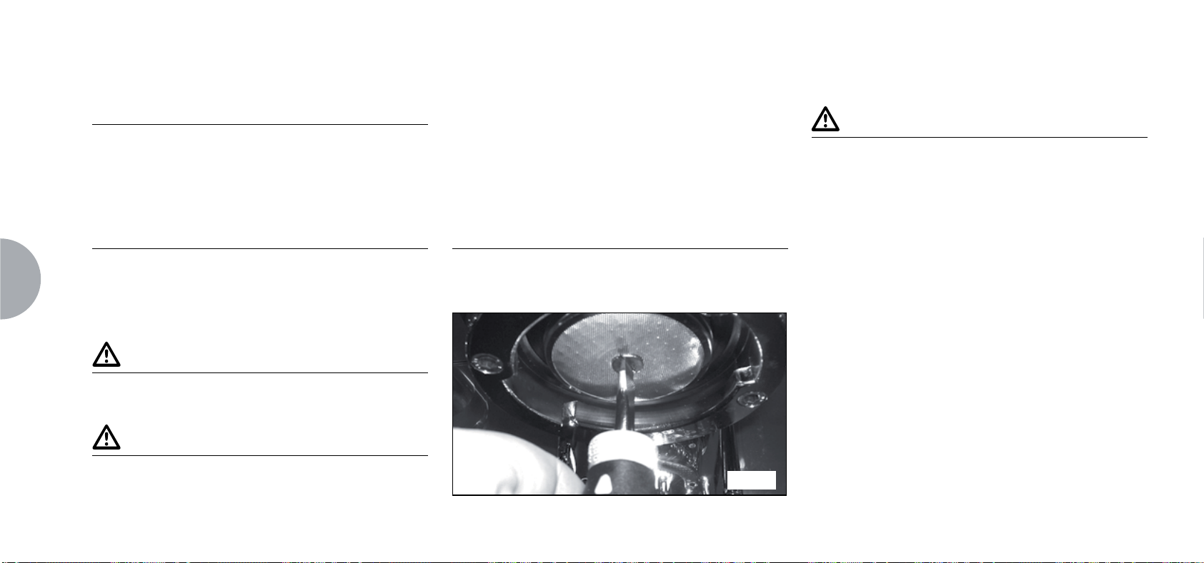
8. CLEANING AND MAINTENANCE
EN
84
8.1 SWITCHING OFF THE MACHINE
To switch the machine off press the main switch and
set the machine to the "O" energy position.
8.2 CLEANING THE OUTSIDE
OF THE MACHINE
The machine must be set to “O” power (switch off and
disconnector open) before any cleaning operations are
performed.
WARNING
Do not use solvents, chlorine-based products or
abrasives.
WARNING
It is not possible to clean the machine using water jets
or standing it in water.
Cleaning the work area: remove the worktop, lifting it
up from the front and sliding it out. Remove the water
collection dish underneath and clean everything with hot
water and cleansers. Cleaning the bottom: To clean
all the chromium-plated areas, use a soft, damp cloth.
8.3 CLEANING THE STAINLESS
COFFEE-HOLDERS
The stainless coffee-holders are situated under the
delivery units, as shown in Fig. 21.
Fig. 21
NOTE
To clean proceed as follows:
Turn the screw placed in the centre of the coffee-
holder.
Slide the coffee-holder out and check that its holes
are not obstructed but clean.
If obstructed, clean as described (Paragraph
“CLEANING FILTERS AND FILTER-HOLDERS”).
We recommend cleaning the coffee-holder once a
week.
Page 87

8.4 CLEANING THE UNIT WITH
THE AID OF THE BLIND FILTER
The machine is pre-set for cleaning the delivery unit
with a specific washing powder.
The machine will initiate washing cycle which consists
in the circulation of hot water followed by regular
breaks.
We recommend carrying out a washing cycle at least
once a day with special cleansers.
CAUTION RISK OF INTOXICATION
Once the filter-holder has been removed, repeat delivery operations a few times to eliminate any cleanser
residues.
To carry out the washing procedure, proceed as follows:
① Substitute the filter with the delivery unit blind filter.
② Fill it with two spoonfuls of special cleanser pow-
der and insert it into the unit filter-holder.
③ Press one of the coffee keys and halt it after 10
seconds.
④ Repeat the procedure several times.
⑤
Remove the filter-holder and carry our a few deliveries.
8.5 CLEANING FILTERS AND
FILTER-HOLDERS
Place two spoonfuls of special cleanser in half a litre of
hot water and immerse filter and filter-holder (without
its handle) in it leaving them to soak for at least half an
hour. Then rinse abundantly with running water.
EN
85
Page 88

9.
MACHINE FUNCTION MESSAGES
EN
86
DISPLA Y AND KEY
INDICATIONS
DIAGNOSIS OF ERROR
DELIVERY ERROR
DOSER ERROR
LEVEL ERROR
CAUSE EFFECT SOLUTION NOTES
At the time of the diagnosis the
system presents faults within the
control unit EPROM.
On reaching delivery time limit
(120 seconds) the doser doesn’t
send out its set commands.
If the doser doesn’t send out its
set commands within the ¿rst
three seconds from delivery
onset.
If after 90 sec of machine functioning the water level is not re-
established.
If after 90 sec of machine functioning the water level is not re-
established.
The display indicator and the
‘continuous’ key belonging to the
relative unit will Àash on and off.
If the delivery isn’t manually halted, the maximum time limit (120
sec) will be blocked.
The display indicator will Àash
on and off. The pump is de-activated. The resistor and all the
functions are halted.
Press the RESET key or one of
the keys
Press the RESET key or one of
the keys
Turn the machine off and then
turn it on again. All its functions
will be re-activated.
WV.
WV.
Page 89

DISPLA Y AND KEY
INDICATIONS
CAUSE EFFECT SOLUTION NOTES
PRESSURE ERROR
OVERCURRENT ERR.
FINE GRINDING
COARSE GRINDING
When the machine’s tempera-
ture is higher than 130°C.
Incorrect electrical input caused
by a malfunction in one of the
machine charges.
The machine registers values
different from the set values.
The machine registers values
different from the set values.
The display indicator will Àash
on and off and the resistor is de-
activated.
The display reading will Àash. The
pump will switch off. The heating
element and all other functions
will be disabled.
A much longer delivery time.
A much shorter delivery time.
The system will be re-established as soon as the tempera-
ture goes below 130°C.
Switch off the machine and send
for a specialist technical
engineer.
Modify grinding degree and
press the key RESET or one of
the keys
Press the RESET key or one of
the keys
WV.
WV.
The boiler is provided with a manual re¿tting safety thermostat; if
the resistor is not re-established,
call a quali¿ed technician.
EN
By leaving the machine in the
programming state, within 10
minutes from the last selection,
the system will return to the
previous con¿guration and the
display will indicate its reestab-
lishment of normal functioning.
87
Page 90

EN
88
Page 91

Tous nos compliments pour avoir choisi une machine unique en son genre.
Lisez attentivement les indications contenues dans la notice d’instructions pour “préparer” votre
.
Vous apprécierez la facilité d’opération pour obtenir d’excellents cafés et des cappuccinos crémeux.
Avec le temps, vous remarquerez aussi que votre nouvelle machine requiert un entretien minimum.
Victoria Arduino
FR
89
Page 92

90
FR
Page 93

Modèle: 2 groupes - Poids Net: 84 Kg - Poids Brut: 90 Kg - Puiss. Thermique: 4500 W - Capacité chaudière 14 lt - Volts 230-380V 50/60Hz
Modèle: 3 groupes - Poids Net: 98 Kg - Poids Brut: 108 Kg - Puiss. Thermique: 5000 W - Capacité chaudière 17 lt - Volts 230-380V 50/60Hz
La marque d’approbation certifie que toutes les machines ont été soumises à des tests d’essai et à des contrôles minutieux
FR
91
Page 94

SOMMAIRE
CARACTÉRISTIQUES TECHNIQUES.................91
1. NOTES GÉNÉRALES A LA LIVRAISON..............93
1.1 PRESCRIPTIONS DE SÉCURITÉ.......................................................93
2. DESCRIPTION ..................................................... 97
2.1 LISTE ACCESSOIRES ....................................................................... 98
3. TRANSPORT ET DÉPLACEMENT ...................... 99
3.1 IDENTIFICATION DE LA MACHINE ....................................................99
6. UTILISATION ...................................................... 106
6.1 PROCÉDURE DE PREMIERE INSTALLATION OU APRÈS
L’ENTRETIEN DES CHAUDIÈRES (VERSION T3) ............................106
6.2 MISE EN MARCHE DE LA MACHINE ...............................................106
6.3 ALLUMAGE VOYANTS LUMINEUX .................................................. 108
6.4 LÉGENDE TOUCHES (Configuration sélections) ................................108
6.5 RÉGLAGE FLUX DE LA VAPEUR.....................................................109
6.6 RÉGLAGE LANCE TURBOCREAM (Si Installée) ............................... 109
6.7 RÉGLAGE LANCE AUTOSTEAM (Si Installée) .................................. 110
7. PROGRAMMATION ............................................111
7.1 LÉGENDE ........................................................................................111
7.2 AFFICHAGE (Mod. UTILISATEUR) ..............................................................111
7.3 PROGRAMMATION (Mod. TECHNICIEN) ..................................................114
92
FR
4. INSTALLATION ET OPÉRATIONS
PRÉLIMINAIRES ................................................ 100
5. RÉGLAGES DU TECHNICIEN QUALIFIE ......... 102
5.1 REMPLISSAGE MANUEL DE LA CHAUDIÈRE .................................102
5.2 RÉGLAGE POMPE .......................................................................... 103
5.3 RÉGLAGE ÉCONOMISEUR EAU CHAUDE ......................................104
5.4 REMPLACEMENT DE LA BATTERIE DE LA MONTRE.......................... 105
8. NETTOYAGE ET ENTRETIEN ...........................129
8.1 ARRÊT DE LA MACHINE .................................................................129
8.2 NETTOYAGE DE LA CARROSSERIE ...............................................129
8.3 NETTOYAGE DES DOUCHES INOX ................................................ 129
8.4 NETTOYAGE DU GROUPE AVEC L’AIDE DU FILTRE BORGNE .......130
8.5 NETTOYAGE DES FILTRES ET DES SUPPORTS A FILTRES ...........130
9. MESSAGES FONCTIONS MACHINE................ 131
Page 95

1. NOTES GÉNÉRALES A LA LIVRAISON
1.1 PRESCRIPTIONS DE SÉCURITÉ
➊
Ce manuel est partie intégrante et essentielle du
produit et doit par conséquent être remis à l’utilisateur.
Lire attentivement les conseils qu’il contient car ils fournissent des indications particulièrement importantes
sur la sécurité de l’installation, son utilisation et son
entretien.
Conserver ce manuel avec soin de façon à pouvoir le
consulter si nécessaire.
RISQUE DE POLLUTION
➋
Après avoir retiré la machine de son emballage,
contrôler que l’appareil soit en parfait état. En cas du
moindre doute, ne pas l’utiliser et s’adresser à un technicien qualifié. Les éléments de l’emballage (sacs plastique,
polystyrène expansé, clous, etc.) ne doivent pas être laissés à la portée des enfants car ils peuvent être dangereux.
Ne pas répandre ces éléments dans l’environnement.
➌
Avant de brancher l’appareil, veillez à ce que les
données indiquées sur la plaquette correspondent à
celles du réseau électrique. La plaquette est située sur
le devant de l’appareil, en haut à droite. L’installation
doit être réalisée dans le respect des normes en
vigueur, suivant les instructions fournies par le fabricant
et par un technicien qualifié.
Le fabricant ne pourra en aucun cas être retenu responsable des éventuels dommages causés par une
absence de mise à la terre de l’installation. Pour la
sécurité électrique de cet appareil, il est obligatoire de
prévoir une installation de mise à la terre, en s’adressant à un électricien qualifié et dûment autorisé à cet
effet, afin qu’il vérifie que la portée électrique de l’installation soit bien appropriée à la puissance maximum
de l’appareil indiquée sur la plaquette.
En particulier, l’électricien devra s’assurer que la section des câbles de l’installation soit bien adaptée à la
puissance absorbée par l’appareil.
L’emploi d’adaptateurs de même que de prises multiples et de rallonges est interdit. Si leur usage s’avère
indispensable, il faut absolument s’adresser à un électricien dûment autorisé à cet effet.
➍
Durant l’installation du dispositif, utiliser les composants et les matériaux fournis en dotation avec le
dispositif. Si l’utilisation de composants supplémentaires s’avère nécessaire, l’installateur doit vérifier
l’adéquation de ces derniers pour un emploi au contact
de l’eau pour la consommation humaine.
➍
bis
La machine doit être installée conformément
aux normes en vigueur, en matière de santé, pour les
installations hydrauliques. Il faut donc que l'installation
hydraulique soit réalisée par un technicien autorisé.
❺
L'alimentation du dispositif doit être effectuée avec
de l’eau adéquate pour la consommation humaine
conformément aux dispositions en vigueur dans le pays
FR
93
Page 96

FR
d’installation. L’installateur doit recevoir de la part du
propriétaire/gérant de l’installation, une confirmation
écrite indiquant que l’eau respecte les caractéristiques
susmentionnées.
➏
Cet appareil devra être destiné uniquement à
l’usage décrit expressément dans cette notice. Le fabricant ne pourra en aucun cas être retenu responsable
des dommages éventuels causés par une mauvaise ou
déraisonnable utilisation.
REMARQUE
Avant d’utiliser la machine, lire entièrement le manuel
de mode d’emploi et les prescriptions de sécurité et de
mise au point.
❼
L’appareil n’est pas indiqué pour l’utilisation de la part
des enfants, des personnes avec des capacités physiques,
sensorielles ou mentales réduites ou n’ayant pas l’expérience et les connaissances suffisantes, à moins qu’elles
ne soient surveillées ou instruites par des personnes
responsables de leur sécurité.
➑
Les températures maximum et minimum de stoc-
kage doivent être comprises entre [- 5 + 50]°C.
➑
bis
La température de fonctionnement doit être
comprise entre [+5, +35]°C.
➒
Au terme de l’installation, le dispositif doit être
actionné jusqu’à ce qu’il atteigne la condition nominale
de travail en le laissant en condition de “prêt au fonctionnement”. Eteindre ensuite le dispositif et vider entièrement le circuit hydraulique de sa première eau afin
d’éliminer toute impureté éventuelle. Le dispositif doit
être ensuite à nouveau chargé et actionné jusqu’aux
conditions nominales de fonctionnement.
Lorsqu’on atteint la condition “prêt au fonctionnement”,
effectuer les distributions suivantes:
- 100% du circuit café à travers le distributeur de
café (pour plusieurs distributeurs, diviser en mesures
égales);
- 100% du circuit eau chaude à travers le distributeur
d’eau (pour plusieurs distributeurs, diviser en mesures
égales);
- ouverture de chaque sortie vapeur pendant 1 minute.
Au terme de l’installation, il serait préférable de rédiger
un rapport des opérations effectuées.
❿
L’utilisation de tout appareil électrique entraîne le
respect de certaines règles fondamentales. Et notamment:
ne pas toucher l’appareil avec les mains ou les pieds
mouillés ou humides;
ne pas utiliser l’appareil pieds nus;
ne pas employer de rallonges dans des locaux
utilisés comme salle de bain ou douche;
ne pas tirer le câble d’alimentation pour débrancher
l’appareil du réseau électrique;
ne pas laisser l’appareil exposé aux agents atmos-
phériques (pluie, soleil, etc.);
ne pas permettre l’utilisation de l’appareil de la part
d’enfants ou de personnes non autorisées et n’ayant
pas lu ni bien compris le contenu de cette notice.
En phase d’installation, le réseau électrique devra
être prédisposé avec un sectionneur qui sectionne
chaque phase.
94
Page 97

⓫
Le technicien autorisé doit, avant d’effectuer toute
opération d’entretien, débrancher la prise après avoir
éteint l’interrupteur de la machine.
⓫
bis Pour les opérations de nettoyage, positionner la
machine sur l’état énergétique “O”, à savoir “interrup-
teur machine éteint et prise débranchée” et suivre
exclusivement les indications de la notice d’instructions.
⓬
En cas de panne ou de mauvais fonctionnement
de l’appareil, éteignez-le. Il est strictement d’intervenir.
Adressez-vous uniquement au personnel qualifié.
La réparation éventuelle des produits ne devra être
effectuée que par la Maison Constructrice ou par un
centre de service après vente dûment autorisé, en
utilisant uniquement des pièces détachées originales.
L’inobservance de ces indications pourrait compromettre la sécurité de l’appareil.
⓭
Lors de l’installation, l’électricien autorisé devra
prévoir un disjoncteur omnipolaire conforme aux
normes en vigueur qui prévoient que les contacts aient
un espace d’ouverture égal ou supérieur à 3 mm.
⓮
Afin d’éviter des surchauffes dangereuses, il est
conseillé de bien dérouler sur toute la longueur le câble
d’alimentation.
⓮
bis
La câble d’alimentation de cet appareil ne doit
pas être remplacé par l’utilisateur. En cas d’endommagement du câble, éteindre l’appareil et le faire remplacer uniquement par un technicien qualifié.
⓯
Si vous décidez de ne plus utiliser cet appareil, il
est vivement conseillé de le rendre inefficace en coupant le câble d’alimentation, après avoir débranché le
câble du réseau d’alimentation électrique.
ATTENTION RISQUE DE POLLUTION
Ne jamais abandonner l’appareil dans l’environnement:
pour son élimination totale, s’adresser à un centre
autorisé ou contacter le fabricant afin de recevoir les
instructions à ce sujet.
⓰
Pour favoriser l’aération de la machine, positionnez-la à 15 cm des murs et des autres machines.
ATTENTION RISQUE DE BRULURES
⓱
Lors de l’utilisation du bec à vapeur, ne jamais
exposer les mains à la vapeur. Ne jamais toucher le bec
tout de suite après son utilisation.
⓲
Pour effectuer toute opération relative à l’installation, l’entretien, le déchargement et la mise au point,
l’opérateur qualifié devra toujours porter ses gants de
travail et ses chaussures de protection.
⓳
Le niveau maximum de pollution sonore émise est
inférieur à 70db.
⓴
En cas de substitution du tube pour le branchement
hydrique, le vieux tube ne doit plus être réutilisé.
FR
95
Page 98

96
FR
ATTENTION
RENSEIGNEMENT AUX UTILISATEURS
Aux sens de l’art. 13 du Décret
Législatif du 25 juillet 2005, n.
151 “Réalisation des Directives
2002/95/CE, 2002/96/CE et 2003/108/
CE, relatives à la réduction de l’utilisation de substances dangereuses dans les appareillages électriques et électroniques, ainsi qu’à
l’enlèvement des ordures“.
Le symbole de la poubelle barrée reporté sur l’appareillage indique que le produit, à la fin de sa propre vie
utile, doit être recueilli séparément d’autres ordures.
L ‘utilisateur devra, donc, transmettre l ‘appareillage
arrivé à la fin de sa vie aux centres aptes à la récolte
différenciée des déchets électroniques et électrotechniques, ou le rendre au détaillant au moment de l’achat
d’un nouvel appareillage de même type, à raison
d’échange un à un. La récolte différenciée propre pour
le départ successif de l’appareillage laissé au recyclage, au traitement et à l’enlèvement compatible d’un
point de vue de l’environnement, contribue à éviter de
possibles effets négatifs sur le milieu et sur la santé et
il favorise le recyclage des matériels dont l’appareillage
se compose. L’enlèvement illégal du produit de la part
de l’utilisateur comporte l ‘application des sanctions
administratives dont au D.Lgs.n. 22/1997” (article 50 et
suivants du D.Lgs.n.22/1997).
Page 99

2. DESCRIPTION
Poussoirs Groupe de Distribution
- DIGIT - T3
Affichage LCD
Poussoirs Sélection
Eau Chaude / Vapeur
Touches Programmation
Poignée de Réglage
Flux Vapeur
Lance Eau Chaude
Lance Autosteam
Pied Réglable
Chauffe-tasses Électrique
Groupe de Distribution
Lance Vapeur Manuelle
Support à Filtres
Grille Appuie-tasses
Plateau à Gouttes
Interrupteur Général
Machine
Abb. 1
FR
97
Page 100

2.1 LISTE ACCESSOIRES
A12 A11
98
FR
A10
A05
A06
A04
A07
A03
A08
A09
A02
A01
Fig. 2
CODE DESCRIPTION 2 GROUPES 3 GROUPES
A01 Tube arrivée Ǫ” 11
A02
A03 Support à ¿ltres 3 4
A04 Double ¿ltre 2 3
A05 Filtre unique 1 1
A06 Filtre borgne 1 1
A07 Ressort 3 4
A08 Double bec de distribution 2 3
A09 Bec unique de distribution 1 1
A10 Presse café 1 1
A11
A12
Tube évacuation plan de travail
Ø 25 mm - l. 150 cm
11
Chiffon en micro¿bres 1 1
DVD 1 1
 Loading...