

Victoria-05 VITTORIA 8, VITTORIA 10 Instruction Manual
INSTRUCTION MANUAL
for installation and operation of air pellet stove
VITTORIA 8 / VITTORIA 10

Victoria-05 Ltd.
2
CONTENTS
1. INTRODUCTION....................................................................................................................................................................... 3
2. SAFETY INFORMATION............................................................................................................................................................ 3
3. TECHNICAL DATA AND DIMENSIONS....................................................................................................................................... 4
4. SAFETY DEVICES. ..................................................................................................................................................................... 5
5. CONTROL UNIT. ...................................................................................................................................................................... 6
6. COMPONENTS. ....................................................................................................................................................................... 6
7. OPERATING MODE. ................................................................................................................................................................. 6
8. FUEL. ....................................................................................................................................................................................... 7
9. APPLIANCE INSTALLATION. ..................................................................................................................................................... 8
10. APPLIANCE OPERATION. ....................................................................................................................................................... 9
10.1. INITIAL IGNITION. ................................................................................................................................................................. 9
10.2.CONTROL PANEL DESCRIPTION. ................................................................................................................................................ 9
10.2.1. MAIN USER CONTROL PANEL. ..............................................................................................................................................10
10.2.2. TYPES OF MODES OF THE CONTROL UNIT. ...............................................................................................................................10
10.2.3. MAIN MENU. ..................................................................................................................................................................11
10.2.4. INSTALLER SETTINGS. ........................................................................................................................................................12
10.2.5. SERVICE TECHNICIAN SETTINGS. ...........................................................................................................................................13
10.3. COLD TEST. .......................................................................................................................................................................14
11. INSTRUCTION MANUAL. ......................................................................................................................................................14
11.1. WOOD PELLETS LOADING. .....................................................................................................................................................14
11.2. WOOD PELLET REFUELING. ....................................................................................................................................................14
11.3. STARTING UP THE SYSTEM. ....................................................................................................................................................14
12. MAINTENANCE. ...................................................................................................................................................................15
12.1. DAILY CLEANING. ................................................................................................................................................................15
12.2. WEEKLY CLEANING. .............................................................................................................................................................15
12.3. CLEANING ASH FROM THE FLUE CHANNELS. ................................................................................................................................15
12.4. SEASONAL MAINTENANCE (PERFORMED BY THE INSTALLER)............................................................................................................15
12.5. MAINTENANCE AND CONTROL. ...............................................................................................................................................16
15. FREQUENTLY ASKED QUESTIONS. ........................................................................................................................................17
16. TECHNICAL DOCUMENTS. ....................................................................................................................................................18
SPARE PARTS CATALOGUE .........................................................................................................................................................24
WARRANTY CONDITIONS...........................................................................................................................................................25
DIARY ........................................................................................................................................................................................26

12.2018
INSTRUCTION MANUAL for installation and operation of pellet stove VITTORIA 8 / VITTORIA 10
3
1. Introduction.
We congratulate you on the excellent choice!
Do not leave this instruction manual unread. Installation and operation of a pellet stove associated with various legal
obligations, which are explained in this instruction manual. According to the laws and regulations for safe use of
appliances of this class, the purchaser and user of the pellet stove undertake using this instruction manual to inform
themselves for the assembling and the right operation of the appliance.
This instruction manual is provided to assist you and the team that will install, put into operation and service the pellet stove.
Technicians, who will carry out the above activities to the pellet stove, must be trained and competent.
Only adult persons familiar with the instruction manual should operate pellet stove. Persons with limited physical, sensory or
mental abilities or lack of experience and knowledge do not intend pellet stove for use, unless they are instructed and supervised
in the use of the appliance by a person responsible for their safety.
The pellet stove is manufactured and tested in accordance with standardsEN14785, EN60335-1, EN60335-2-102, EN55014-1,
EN55014-2, EN61000-3-2, EN61000-3-3, EN61000-4-2, EN61000-4-4, EN61000-4-5, EN61000-4-11 and meets the approved
technical documentation
Failure to follow the instructions described in this manual can lead to damage and consequences for which the manufacturer is
not held responsible.
2. Safety information.
• Pellet stove is designed to heat air through automated burn in the combustion chamber of wood pellets with a diameter
of Ø 6 mm class A1.
• Warranty is voided by unauthorized use of combustible material.
• The risk that could arise from non-compliance of this instruction manual is - direct contact with electric parts (internal),
contact with fire or hot surfaces.
• Pellet stove is equipped with safety components that guarantee automatically locking in case of failure of any of its
components. Safety components are activated without outside interference.
• Necessary for the proper operating of the pellet stove is its proper installation in accordance with the following
instructions.
• Fire door should not be opened during operation of the pellet stove. The burning process is automated and does not
require external intervention.
• It is not allowed to burn the pellet stove if there are cracks in the glass.
• Under no circumstances there should not be allowed penetration of foreign substances in the firebox or hopper.
• Do not use combustible materials to clean soot in the chimney.
• Turn off the pellet stove from the electric supply before cleaning or servicing.
• Use a vacuum cleaner to clean the combustion chamber and pellet fuel hopper only when pellet stove is cold.
• Do not use water to clean the internal parts of the pellet stove.
• ATTENTION! During operation of the pellet stove there must not be allowed for a child to touch its surface, as it is hot.
Danger of burning!
• The handle of the pellet stove warms as much as the front panel, so it must be operated with a heat-resistant glove.
During operation of the pellet stove flue pipes and fire door are hot.
• Do not place flammable objects and liquids close to the pellet stove.
• NEVER use flammable liquids to ignite and burn the pellet stove.
• Do not obstruct fresh air to enter the room where pellet stove is installed and through the holes on the pellet stove.
• Do not soak pellet stove and do not touch electrical components with wet hands.
• Do not mount any adapters to flue pipes and chimney.
• To operate properly and safely, pellet stove should be installed in a room that is fire-resistant and equipped with
everything needed (electricity, air exchange, vents).
• The temperature of the room where the pellet stove is installed must not be lower than 0˚C.
• Rating label is placed on the back of the pellet stove.
• Keep the instruction manual, warranty card and purchase invoice in good condition, as will be necessary in any inquiries.
After extinction, do not burn the pellet stove again before cleaning the combustion chamber!
Removed pellets from the combustion chamber should not be placed back in the pellet fuel hopper!
Victoria-05 Ltd.
4
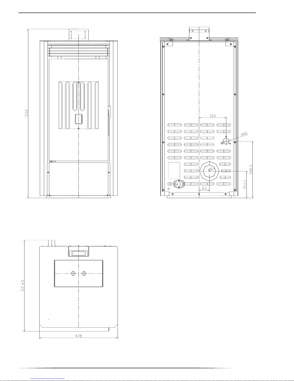
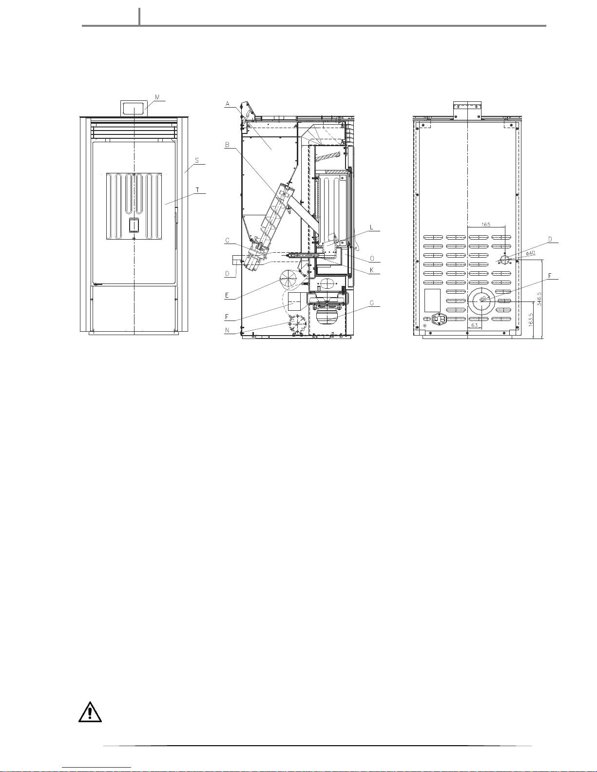
3. Technical data and dimensions.
Drawing.1.
12.2018
INSTRUCTION MANUAL for installation and operation of pellet stove VITTORIA 8 / VITTORIA 10
5
Technical data and nominal performance:
Technical data:
Performance parameters:
Vittoria 8
Vittoria 10
Nominal heat output
6.1 kW
8.0 kW
Reduced heat output
3.0 kW
3.7 kW
Maximum operating temperature
260°С
260°С
Distance to adjacent combustible materials
side = 300 mm
rear = 300 mm
in front = 800 mm
Efficiency
87.76 %
85.87 %
СО emissions [13% О2]
at nominal heat output
at reduced heat output
0.0166 %
0.0281 %
0.0156 %
0.0291 %
Flue gases temperature
at nominal heat output
at reduced heat output
125°С
78°С
181°С
88°С
Flue gases mass
at nominal heat output
at reduced heat output
5.81 gr/s
2.96 gr/s
6.28 gr/s
2.98 gr/s
Draught
at nominal heat output
at reduced heat output
11 Ра
11 Pa
11.5 Ра
10.5 Pa
Duration of combustion
at nominal heat output
at reduced heat output
15h
34h
11h
28h
Fuel consumption minimum / maximum
0.7/1.525kg/h
0.867/2.067 kg/h
Type and dimensions of fuel
Wood pellets, Ø 6 mm/length 25 mm
Pellet fuel hopper capacity
24 kg
24 kg
Flue socket diameter
Ø 80 mm
Ø 80 mm
Heating volume
≈ 120m
3
≈ 155 m
3
Net weight
103 kg
103 kg
The dimensions of the heated room are calculated based on pellets with calorific value not less than 4300 ccal/kg and heat loss of
heated room 33 ccal/m³h.Consideration must be given to the availability of external devices that can influence the operation of
the pellet stove.
All activities for repairing of electrical components, maintenance and / or inspections should be performed by qualified
personnel. Unplug the appliance from the main electrical supply before you start these activities.
Electrical data:
Performance parameters:
Power supply
230 Vac (+/-10%), 50 Hz
Switch on / off
Yes
Average power consumption
130 W
Average power consumption during ignition
430 W
Main power protection
Fuse 4А, 250 VAC5 х 20
We reserve the right to make changes in products without prior notice, in order to improve their performance.
4. Safety devices.
Fume thermocouple: It is placed at the exit of the flue socket to measure the temperature of the flue gases. Controls ignition and
at very high temperature (2600C) triggers lock phase. Alarm (High Temp).
Vacuum gauge: It is placed at the exit of the flue socket. Account values of draught into the combustion chamber and compared
with the pressure in the room.
Temperature sensor of the pellet fuel hopper: Placed on the auger housing near the pellet fuel hopper. It interrupts feeding of the
pellets, if its temperature reaches 75°С.
Fuse: At the main switch of the pellet stove there is built in fuse.
Victoria-05 Ltd.
6
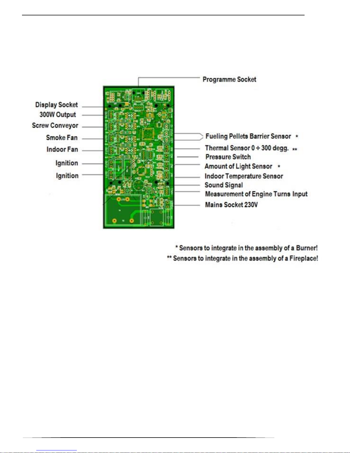
5. Control unit.
The control unit is equipped with a system for monitoring and controlling of the burning process. It ensures higher efficiency,
optimizes the fuel consumption and minimizing the emissions. With sensors for the pressure in the fire chamber and temperature
sensors at the flue outlet for the temperature of the flue gasses, the system analyzes the collected data from the burning and
automatically controls it and optimizes it.
Picture.1.
6. Components.
Ignition:
Performs the ignition of the pellets
Fume extractor:
Extracts the flue gases from the combustion chamber to the flue pipe outlet and intakes combustion air by vacuum.
Gear motor:
Driven auger screw by means of which the pellets are conveyed from the pellet fuel hopper to the combustion chamber.
Room air fan:
Ensures additional circulation of the air in the room.
Pressure Switch (Pressostat):
Measures the pressure in the combustion chamber.
7. Operating mode.
Pellet stove works with wood pellets. They are cylindrical granules, made of pressed wood, whose combustion is controlled by an
electronic control system.
The pellet fuel hopper, position (A) of Picture 2, is located at the rear of the pellet stove. Filling of the hopper is made through a
hatch located in the rear part of the upper top of the pellet stove. The pellets are transported from the hopper (A) to the
combustion chamber (D) by means of a screw auger (B) driven by a gear motor (C).
12.2018
INSTRUCTION MANUAL for installation and operation of pellet stove VITTORIA 8 / VITTORIA 10
7
The initial ignition of the pellets is carried out by hot air, which is sucked in around the ignition (K) in the combustion chamber
through the fume extractor (G). Fume extractor provides combustion air by sucking in from air inlet Ø40 mm (D) by the room or
by outside atmosphere. Upon submission of air from the room must have provided an influx of outside air.
The flue gases are sucked from the combustion chamber through the fume extractor (G) and are conducted to flue socket Ø 80
mm (F).
Picture.2.
The ash from the combustion process is conducted in an ashtray (O)underneath the combustion chamber. The ashtray must be
periodically cleaned by pouring in a metal container or by a vacuum cleaner, but only when the pellet stove is cold.
By the internal mounted air fan (E), the hot air is pushed in the room and multiplies the efficiency of the pellet stove. The room
temperature is measured by temperature sensor installed in the stove.
High efficiency and low emission of the pellet stove is guaranteed by an electronic control system that manages the amount of
fuel, the flue gases conduction, supplying of combustion air and operation of the air fan. The control panel of the control system
is placed in back of the upper panel of the pellet stove (M) from Picture 2. Through the control panel, the user can visualize and
manage all stages of the operation of the pellet stove.
8. Fuel.
Pellet stove e designed and programmed to burn wood pellets. They have a cylindrical shape and they are made of compressed
by a high-pressure timber, without adhesive and additive materials. The wood pellets are sold in packages weighing 15 kg, which
facilitates their storage. For better combustion, the wood pellets must be stored in dry and ventilated area. Pellet stove is designed,
developed, programmed and tested to operate with wood pellets class A1, according to EN plus and BDS EN ISO 17225-2: 2014
with the following parameters:
Maximum diameter: Ø 6 mm
Maximum length: 25 mm
Maximum moisture content: 8 %
Maximum ash content: 0.5%
Minimum calorific value: 4300 ccal/kg
Good quality wood pellets ensure good combustion and lower emissions into the atmosphere.
The use of wood pellets with a lower quality results in a need for more frequent cleaning of the combustion chamber, reducing
heat output and efficiency. They are increasing the fuel consumption sensitively. Inadequate wood pellets can cause blockage of
the auger and to stop the operation of the pellet stove.
IF PELLET STOVE IS BLOCKED, THE REASON WILL APPEAR ON THE DISPLAY AND IT WILL BE SAVED.
Using wood pellets of poor quality or non-manufacturer recommended as above may compromise the operation of the
pellet stove and lead to termination of the warranty.
Pellet stove should not be used to burn other types of fuels or materials. Invalid guarantee!
Victoria-05 Ltd.
8
9. Appliance installation.
Trained and competent technicians or companies must perform the installing a pellet stove! Qualified technicians
should perform all activities in inspection and repair of electrical components. Switch off the pellet stove from the
electric supply before any inspection or repair!
Refer to the regulations valid for the country, where the pellet stove will be used, if you do not find the information you are
interested in this instruction manual.
It is not recommended to install a pellet stove in rooms where there is mounted another heater. If it does, it must be equipped
with a separate air duct.
Compatibility with other devices:
Pellet stove should not be installed in the same room in which there are absorbers and / or devices that reduce ventilation in the
room.
Checking electrical connections:
Pellet stove is equipped with a power cable to be connected to a voltage 230V / 50Hz. Changes exceeding by 10% the voltage can
damage the appliance. Electrical grid-circuit must comply with the provisions of the laws and requirements for grounding.
According to the requirements for electrical grid-circuit connection, pellet stove should be installed so as to ensure free access to
the plug and socket (230V / 50Hz). According to the safety requirements it’s prohibited the room where the pellet stove is installed
to have electrical installation mounted on the floor. Lack of bonding / grounding can cause damage for which the manufacturer is
not responsible.
Positioning:
To ensure well operation, pellet stove should be leveled. The floor on which is placed the pellet stove must be of non-combustible
materials (concrete, marble, terracotta, etc.)
Given the easy servicing and refueling, we recommend the following minimum free distance around the pellet stove: 1000 mm at
the front, back and sides -500 mm, top -minimum 1000 mm.
Safe distances for fire safety:
When installing a pellet stove and storage of wood pellets must be respected the fire requirements!
It is recommended that an appropriate place to mount a fire extinguisher be ensured.
It is forbidden to store the wood pellets directly to the pellet stove or a distance of less than 400 mm.
The optimal distance between the pellet stove and combustible materials is 800mmin front and 300 mm from the sides and the
back. Inflammable objects should not be placed on the top board of the pellet stove.
If the chimney is connected to the timber wall or other inflammable material, suitable materials such as ceramic wool should be
used to isolate it.
Fresh air opening:
Imperative to ensure submission of fresh air!
The room, in which is mounted pellet stove must have an opening for fresh air with a cross section of not less than 80 cm² in order
to ensure a sufficient supply of oxygen necessary for combustion. Additionally, it can be delivered outside air through a steel pipe
of Ø 50 mm. In this case, it is possible to emerge condensate. If necessary, the opening for external air can be protected by a grid
whose light-section should not be less than 12 cm². Pipe for outside air has to be mounted on the nearest outer wall to the pellet
stove. Its length should not exceed 1 m, should not have curves and its location has to prevent clogging. The outer end of the pipe
must end with a knee 90˚, downward or be provided with protection against wind.
Chimneys:
Pellet stove works constantly with a fume extractor and pressure in the flue pipes and chimney.
It is forbidden flue gases to be discharged directly from the pellet stove through the wall into the atmosphere. Required installed
chimney, which takes flue gases safe for human health altitude over the area of habitation.
Only the pellet stove should use chimney and no other appliances have to be connected to it. The flue gases are emitted from the
combustion chamber of the pellet stove to the atmosphere through a flue socket Ø 80 mm located in the rear. It is recommended
at the beginning of the vertical section of the chimney to mount a T-fitting, with a section for collecting condensate. Pellet stove
must be connected to the chimney by steel flue pipes, certified according to EN 1856. The flue pipe system must be hermetically
insulated with materials resistant to high temperatures (heat-resistant silicone or grease). Allowed to have a horizontal section
with a length of 2 m. Horizontal section must be a minimum slope of 3% and not more than two curves at 90°.
If the flue socket of the pellet stove is connected to a metal chimney, it must have a vertical portion length of not less than 1.5 m
and fitted with a wind protection. Chimney may be located internally or externally. It should be well insulated.
If the pellet stove is connected to a masonry chimney, it must be intended for appliances for solid fuel. If the chimney has a size
larger from Ø150 mm in diameter, internally along its entire length must be installed tube of stainless steel with a diameter of
Ø150 mm, as the free space has to be isolated by masonry. All parts of the chimney should have free access to inspection. At the
12.2018
INSTRUCTION MANUAL for installation and operation of pellet stove VITTORIA 8 / VITTORIA 10
9
bottom of the chimney must be built manhole allowing opening and cleaning at least once a year. On top of the chimney must be
installed a wind protection hat, according to current regulations.
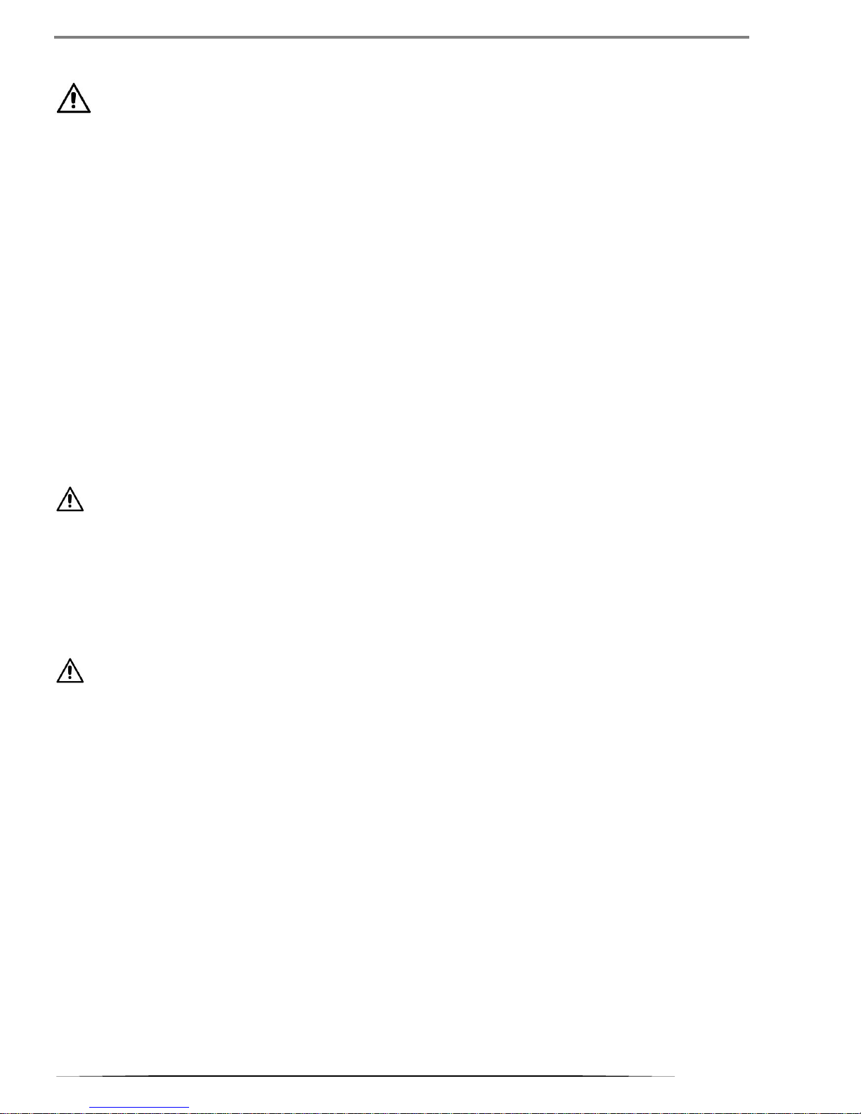
Picture.3.
А -Insulated metal chimney.
В -Minimum height of 1.5 meters beyond the eaves of the roof.
С -Incoming outside air through the section with minimum cross section of 80 сm2.
Е -Incoming outside air through the section with minimum cross section of 80 cm.
D -Metal pipe in masonry chimney.
10. Appliance operation.
10.1. Initial ignition.
The installer of the pellet stove should perform the initial release!
The installer is obligated to:
- to check the dimensions of the connecting flue pipes and chimney;
- to set the pellet stove according to the type of wood pellets used;
- to carry out emission control of flue gases after installation;
- to make a detailed instruction of the user;
Pellet stove is coated by high temperature resistant paint, but not against corrosion. In case of accumulation of dust, surfaces can
be cleaned with a soft brush or a dry cloth, but in any case not with a damp cloth or water.
Upon initial ignition do not place any objects on the pellet stove and do not touch the outer surface to avoid damaging the coating.
The flavor, which is obtained as a result of the drying of the paint, disappears after a few hours. Ventilate the room where is
located the pellet stove.
If as a result of overheating or due to incorrect operation color changes, appeared stain rust or damaged part of the coverage, it
is not a problem. You can order spray paint to your dealer.
Before ignition, check: power, door seal, if the combustion chamber is cleaned and whether the display is switched to
standby mode.
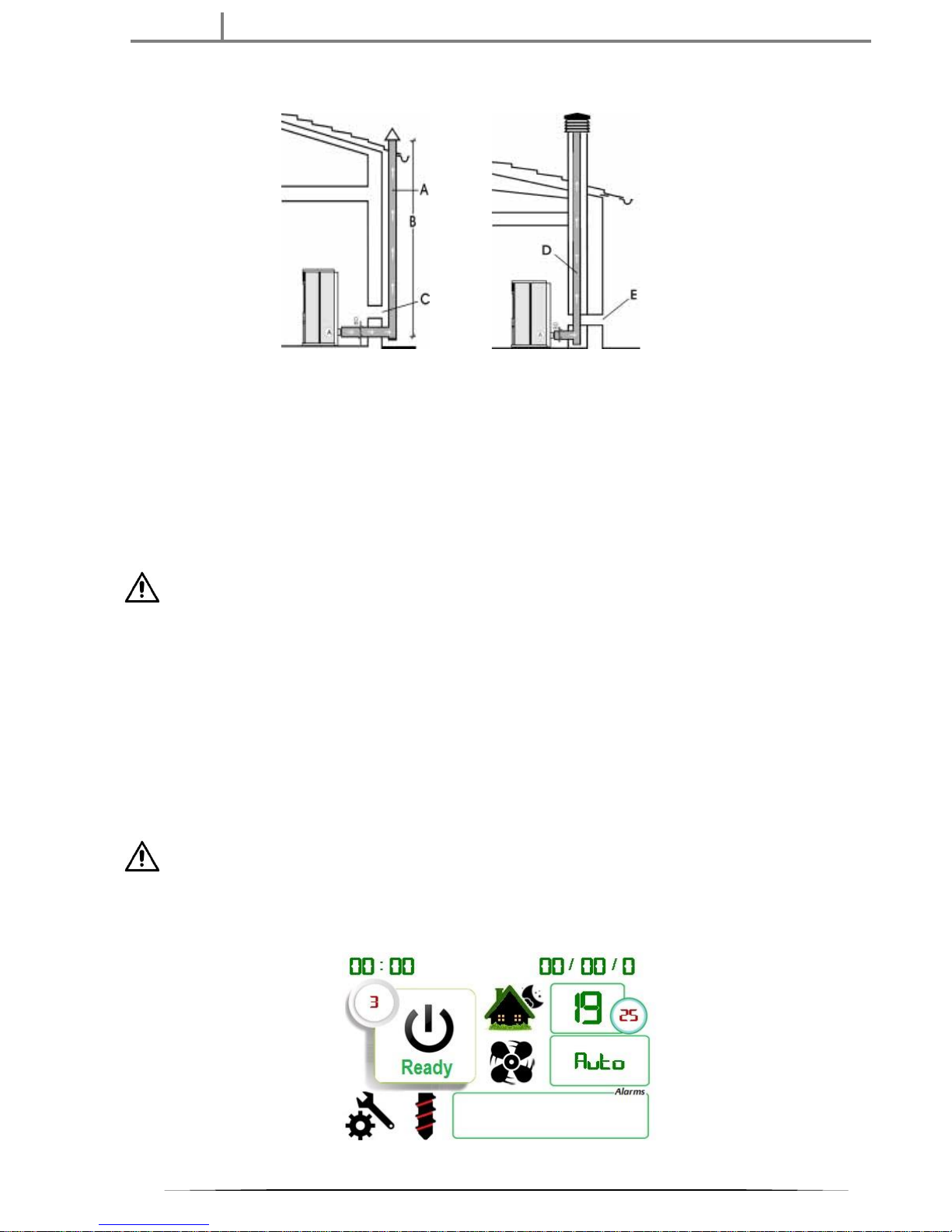
10.2.Control panel description.
After start up, on the control display is shown the logo of Victoria-05 for 3 seconds and then switches to main user panel. The icons
and functions are shown as follows:
Picture.4.
 Loading...