

Victoria Vittoria B Instruction Manual

INSTRUCTION MANUAL
for installation and operation of pellet stove
VITTORIA В*

Victoria-05 Ltd.
2
CONTENTS
1. INTRODUCTION. .................................................................................................................................................................. 3
2. SAFETY INFORMATION. ....................................................................................................................................................... 3
3. TECHNICAL DATA AND DIMENSIONS. .................................................................................................................................. 4
4. SAFETY DEVICES. ................................................................................................................................................................. 5
5. ELECTRICAL WIRING DIAGRAM. .......................................................................................................................................... 6
6. COMPONENTS. .................................................................................................................................................................... 6
7. OPERATING MODE. ............................................................................................................................................................. 7
8. FUEL. ................................................................................................................................................................................... 8
9. APPLIANCE INSTALLATION. ................................................................................................................................................. 8
10. APPLIANCE OPERATION. ......................................................................................................................................................11
10.1. INITIALLY IGNITION. .............................................................................................................................................................11
10.2. CONTROL PANEL DESCRIPTION. ...............................................................................................................................................11
10.3. COLD TEST. .......................................................................................................................................................................12
11. INSTRUCTION MANUAL. ......................................................................................................................................................12
11.1. WOOD PELLETS LOADING. .....................................................................................................................................................12
11.2. WOOD PELLET REFUELING. ....................................................................................................................................................13
11.3. IGNITION. .........................................................................................................................................................................13
11.4. CONTROL PANEL. ................................................................................................................................................................13
12. MAINTENANCE. ...................................................................................................................................................................14
12.1. DAILY CLEANING. ................................................................................................................................................................14
12.2. WEEKLY CLEANING. .............................................................................................................................................................14
12.3. CLEANING ASH FROM THE FLUE CHANNELS. ................................................................................................................................15
12.4. SEASONAL MAINTENANCE (PERFORMED BY THE INSTALLER). ..........................................................................................................15
12.5. MAINTENANCE AND CONTROL. ...............................................................................................................................................15
13. POSSIBLE DEFECTS AND THEIR CAUSES. ...............................................................................................................................15
14. CHECKLIST. ...........................................................................................................................................................................17
15. FREQUENTLY ASKED QUESTIONS. ........................................................................................................................................17

10.2016
INSTRUCTION MANUAL for installation and operation of pellet stove VITTORIA В*
3
1. Introduction.
We congratulate you on the excellent choice!
Do not leave this instruction manual unread. Installation and operation of a pellet stove associated with various legal
obligations, which are explained in this instruction manual. According to the laws and regulations for safe use of
appliances of this class, the purchaser and user of the pellet stove undertake using this instruction manual to inform
themselves for the assembling and the right operation of the appliance.
This instruction manual is provided to assist you and the team that will install, put into operation and service pellet stove.
Technicians, who will carry out the above activities to the pellet stove, must be trained and competent.
Pellet stove operated only by adult persons familiar with the instruction manual. Pellet stove is not intended for use by persons
with limited physical, sensory or mental abilities or lack of experience and knowledge, unless they are instructed and supervised
in the use of the appliance by a person responsible for their safety.
Pellet stove is manufactured and tested in accordance with standards EN 14785, EN 60335-1, EN 60335-1-102, EN 55014-1, EN
61000-6-1, EN 61000-6-3 and meets the approved technical documentation.
Failure to follow the instructions described in this manual can lead to damage and consequences for which the manufacturer is
not responsible.
2. Safety Information.
• Pellet stove must not run without water in the system and the pressure must not fall below 1 bar. Should the system be
alighted without water, pellet stove can be damaged.
• Pellet stove is designed to heat water through automated burn in the combustion chamber of wood pellets with a
diameter of Ø 6 mm.
• Warranty is voided by unauthorized use of combustible material.
• The risk that could arise from non-compliance of this instructions manual is a direct contact with electric parts (internal),
contact with fire or hot surfaces.
• Pellet stove is equipped with safety components that guarantee lock it automatically in case of failure of any of its
components. Safety components are activated without outside interference.
• Necessary for the proper operating of the pellet stove is its proper installation in accordance with the following
instructions.
• Fire door should not be opened during operation of the pellet stove. The burning process is automated and does not
require external intervention.
• Do not allow to burn the pellet stove if there are cracks in the glass.
• Under no circumstances should not be allowed penetration of foreign substances in the firebox or hopper.
• Do not use combustible materials to clean soot in the chimney.
• Turn off the pellet stove from the grid-circuit before cleaning or servicing.
• Use a vacuum cleaner to clean the combustion chamber and pellet fuel hopper only when pellet stove is cold.
• Do not use water to clean the internal parts of the pellet stove.
• ATTENTION! During operation of the pellet stove must not be allowed to touch a child to its surface as it is hot. Danger
of burns!
• The handle of the pellet stove warms as much as the front panel, so it must be operated with a heat-resistant glove.
During operation of the pellet stove flue pipes and fire door are hot.
• Do not place flammable objects and liquids away from the pellet stove.
• NEVER use flammable liquids to burn the pellet stove.
• Do not obstruct fresh air to enter the room where pellet stove is installed and through the holes on the pellet stove.
• Do not soak pellet stove and do not touch electrical components with wet hands.
• Do not mount any adapters to flue pipes and chimney.
• To operate properly and safely, pellet stove should be installed in a room that is fire-resistant and equipped with
everything needed (electricity, air exchange, vents).
• The temperature of the room where it is installed the pellet stove must not be lower than 0˚C.
• Use appropriate non-freezing additives for water in the system.
• Make sure the temperature of the return water is not lower than 45˚C.
• Rating label is placed on the back of the pellet stove.
• Keep this instruction manual, warranty card and purchase invoice in good condition, as will be necessary in any inquiries.
In extinction, doth not burn a pellet stove again before cleaning the combustion chamber!
Removed pellets from the combustion chamber should not be placed back in the pellet fuel hopper!
Victoria-05 Ltd.
4
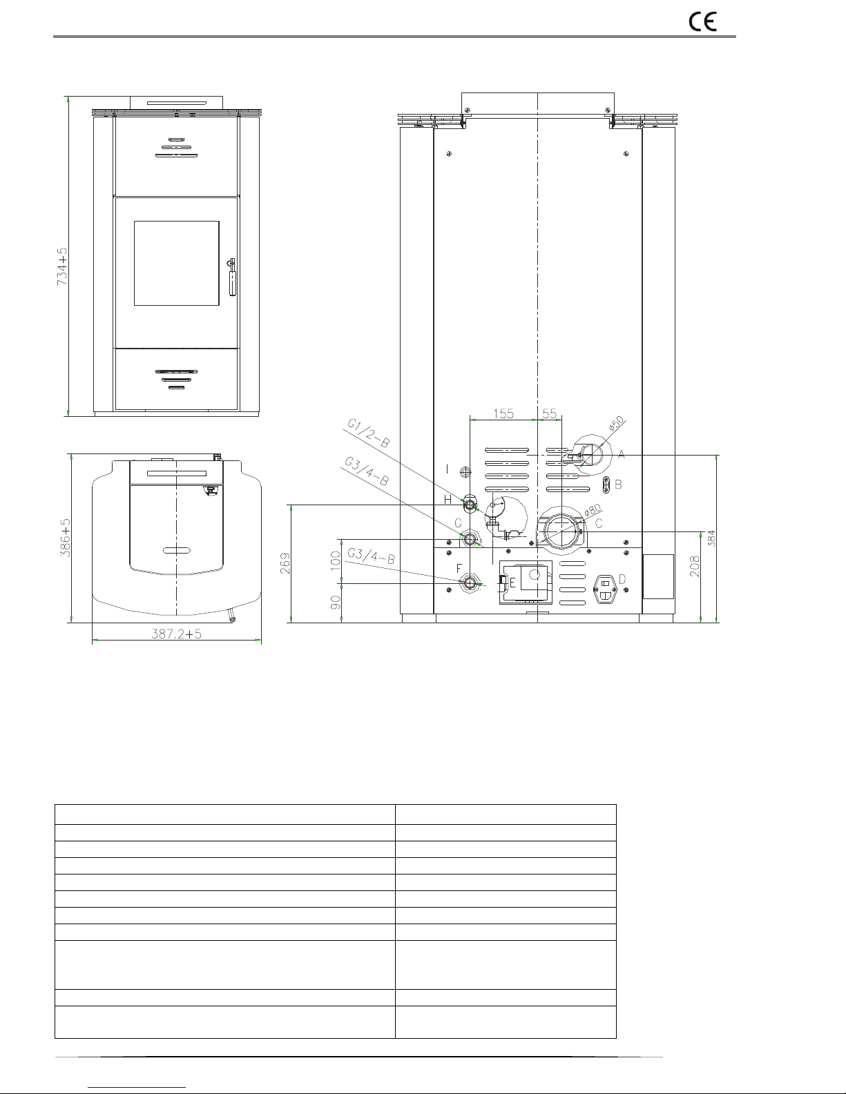
3. Technical data and dimensions.
Fig.1.
А - Air inlet Ø 50 mm
В - Socket RS 232
С - Flue socket Ø 80 mm
D - Main switch with integrated socket for power cable
E - Circulation pump
F - Cold water inlet G ¾“
G - Hot water outlet G ¾“
H - Outlet pipe G ½“ for safety valve (3 bar)
I - Button with safety cover to reset the thermostat
Technical data and performance:
Technical data:
Performance:
Nominal heat output
18.27 kW
Space heating output
2.16 kW
Water heating output
16.11 kW
Reduced heat output
9.79 kW
Operating water pressure
1.5 bar
Test water pressure at installation
3.0 bar
Maximum operating temperature
85°С
Distance to adjacent combustible materials
side = 400 mm
rear = 400 mm
in front = 800 mm
Efficiency
92.4 %
СО emissions [10% О2]
at nominal heat output 0.0132 %
10.2016
INSTRUCTION MANUAL for installation and operation of pellet stove VITTORIA В*
5
at reduced heat output
0.0512 %
Flue gases temperature
at nominal heat output
at reduced heat output
108°С
77°С
Flue gases mass
at nominal heat output
at reduced heat output
12.23 gr/s
8.46 gr/s
Draught
at nominal heat output
at reduced heat output
10.5 Ра
10.0 Pa
Duration of combustion
at nominal heat output
at reduced heat output
4.9 h
17.5 h
Fuel consumption minimum / maximum
1.2 / 4.3 kg/h
Type and dimensions of fuel
Wood pellets, Ø 6 mm/ length 25 mm
Integral boiler capacity
22 l
Expansion vessel capacity
8 l
Cold and hot water inlets dimensions
3/4"
Pellet fuel hopper capacity
26 kg
Flue socket diameter
Ø 80 mm
Heating volume
≈ 470 m
3
Net weight
268 kg
The dimensions of the heated room are calculated based on pellets calorific value not less than 4300 ccal/kg and heat loss of
heated room 33 ccal/m³h. Consideration must be given the capacity of the radiators in the system and the availability of external
devices that can influence the operation of the pellet stove.
All activities for repairing of electrical components, maintenance and / or inspections should be performed by qualified
personnel. Unplug the appliance from the main electrical supply before you start these activities.
Electrical data:
Performance:
Power supply
230 Vac (+/-10%), 50 Hz
Switch on / off
Yes
Average power consumption
156 W
Average power consumption during ignition
375 W
Remote control / frequency remote control
Frequency 2.4 GHz / infrared
Main power protection
Fuse 2А, 250 VAC5 х 20
Protection of electrical switchboard
Fuse 2А, 250 VAC5 х 20
We reserve the right to make changes in products without prior notice, in order to improve their performance.
4. Safety devices.
Fume thermocouple: It is placed at the exit of the flue socket to measure the temperature of the flue gases. Controlled
ignition as at very high or very low temperature trigger lock phase (Stop Flame).
Vacuum gauge (option): It is placed at the exit of the flue socket. Account values of draught into the combustion chamber
and compared with the pressure in the room.
Thermostat: To prevent overheating of the system, with manual reset. Measure the temperature of the water into the
integral boiler. When it reach a value of 90°C, it interrupts power to the gear motor of the auger. If the thermostat has
been activated, it must be reset manually by pressing the switch on the back of the pellet stove (see Fig. 1., Pos. I).
Thermostat of the pellet fuel hopper: Placed on the auger housing near the pellet fuel hopper. It interrupts feeding of the
pellets, if its temperature reaches 120°C.
Thermoregulator: Measure the temperature of the water in the integral boiler and sends information to the control
system. If the measured temperature value reaches 90°C, triggered phase locking (Stop Flame).
Hydraulic safety valve: Upon reaching a pressure of 3.0 bar, the system is activated to emit liquid. After discontinuation
of the emergency, the system must be added to the required pressure (1.5 bar).
Fuse: At the main switch of the pellet stove has built two fuses, one of whom is working and the other is a spare.

Victoria-05 Ltd.
6
5. Electrical wiring diagram.
Diagram 1
1. Control of fume extractor electric motor
2. Air inlet sensor
3. Thermoregulator (sensor for temperature of hot water)
4. Vacuum gauge (option)
5. Fume thermocouple (sensor for temperature of flue
gases)
6. Power supply with integrated fuse and switch
7. Ignition
8. Thermostat of the pellet fuel hopper (sensor for
temperature of auger housing)
9. Thermostat (with manual reset, 90°С)
10. Gear motor
11. Circulation pump
12. Fume extractor
13. Power supply cable for fume extractor
14. Control system
15. Ribbon cable
16. Control panel
17. Coupling
Option: When the pellet stove is equipped with a system for monitoring and control of the combustion process (vacuum gauge),
providing higher thermal efficiency, optimize pellets consumption and minimize harmful emissions. By pressure sensors in the
combustion chamber and flue gases outlet, the system records and analyzes data from the combustion process, compares them
with set parameters and automatically adapts to the characteristics of the chimney (curves, length, shape, diameter), variable
weather conditions ( wind, humidity, atmospheric pressure, high altitude) and characteristics of the pellets (composition, density,
humidity). The system provides continuous combustion process by automatically monitoring the remaining amount of fuel.
6. Components.
Ignition:
Performs ignition of the pellets. Remains switch on until the temperature of flue gases rose 15˚C to the original.
Fume extractor:
Provides the flue gases from the combustion chamber to the flue pipes and combustion air intake by vacuum.

10.2016
INSTRUCTION MANUAL for installation and operation of pellet stove VITTORIA В*
7
Gear motor:
Driven auger screw by means of which the pellets are conveyed from the pellet fuel hopper to the combustion chamber.
Circulation pump:
Provides forced circulation of the fluid in the heating system.
Closed expansion vessel:
Compensate for differences in the volume of liquid in the integral boiler of the pellet stove when heated. Technically competent
person should assess the need for adding a second expansion vessel to the existing, depending on the total amount of fluid in the
heating system.
Air vents (manual and automatic):
They are placed in the upper body of the pellet stove and allow removal of air entered when filling the heating system with liquid
(Figure 3).
Do not forget to connect the heating system to the sewer.
7. Operating mode.
Pellet stove works with wood pellets. These are cylindrical granules, made of pressed wood whose combustion is controlled by an
electronic control system. The heat from the combustion process is given the fluid in the heating system.
The pellet fuel hopper, position (A) of Figure 2, is located at the rear of the pellet stove. Filling of the hopper through a hatch
located in the rear part of the upper top of the pellet stove. The pellets are transported from the hopper (A) to the combustion
chamber (D) by means of a screw auger (B) driven by a gear motor (C).
The initial ignition of the pellets is carried out by hot air which is sucked in around the ignition (E) in the combustion chamber (D)
through the fume extractor (F). Fume extractor (F) provides combustion air by sucking in from air inlet Ø 50 mm (pos. A in Figure
1) by the room or by outside atmosphere. Upon submission of air from the room must have provided an influx of outside air.
The flue gases are sucked from the combustion chamber through the fume extractor (F) and are conducted to flue socket Ø 80
mm (pos. C in Figure 1).
Fig.2. Fig.2.1. Fig.3.
The ash from the combustion process is conducted in an ashtray underneath the combustion chamber. The ashtray must be
periodically cleaned by pouring in a metal container or by a vacuum cleaner, but only when the pellet stove is cold.
Through built-in circulating pump position (K) of Figure 2.1, hot water passes from the integral boiler to the heating system. The
filling and emptying of the heating system is carried out via a built-in shut-off valve position (J) of Fig.2.1. The system pressure is
controlled by pressure gauge built into the front of the top board.
High efficiency and low emission of the pellet stove is guaranteed by an electronic control system that manage the amount of fuel,
the flue gases conduction, supplying of combustion air and operation of the circulating pump. The control panel of the control
J
C
G
A
F
D
E

Victoria-05 Ltd.
8
system is placed in front of the upper panel of the pellet stove (G) in Figure 2. Through the control panel can visualize and manage
all stages of the operation of the pellet stove.
8. Fuel.
Pellet stove e designed and programmed to burn wood pellets. They have a cylindrical shape and they are made of compressed
by a high-pressure timber, without adhesive and additive materials. The wood pellets are sold in packages weighing 15 kg., which
facilitates their storage. Better combustion, the wood pellets must be stored in dry and ventilated area. Pellet stove is designed,
developed, programmed and tested to operate with wood pellets class A1, according to EN plus and BS EN ISO 17225-2: 2014 with
the following parameters:
Maximum diameter: Ø 6 mm
Maximum length: 25 mm
Maximum moisture content: 8 %
Maximum ash content: 0.5%
Minimum calorific value: 4300 ccal/kg
Good quality wood pellets ensure good combustion and lower emissions into the atmosphere.
The use of wood pellets with a lower quality results in a need for more frequent cleaning of the combustion chamber, reducing
heat output and efficiency. They increases the fuel consumption sensitively. Inadequate wood pellets can cause blockage of the
auger and to stop the operation of the pellet stove.
IF PELLET STOVE BLOCKED, THE REASON WILL APPEAR ON THE DISPLAY AND IT WILL BE SAVED.
Using wood pellets of poor quality or non-manufacturer recommended above may compromise the operation of the
pellet stove and lead to termination of the warranty.
Pellet stove should not be used to burn other types of fuels or materials. Invalid guarantee!
9. Appliance installation.
Trained and competent technicians or companies must perform installing a pellet stove and heating system! The
manufacturer does not warrant the operation of the heating system, but only for pellet stove. Qualified technicians
should perform all activities in inspection and repair of electrical components. Switch off the pellet stove from the grid-
circuit before any inspection or repair!
Refer to the regulations valid for the country, which will be used pellet stove if you do not find the information you are interested
in this instruction manual.
Not recommended installing a pellet stove in rooms where there is mounted another heater. If it does, it must be equipped with
a separate air duct.
Compatibility with other devices:
Pellet stove should not be installed in the same room in which there absorbers and / or devices that reduce ventilation in the
room.
Checking electrical connections:
Pellet stove is equipped with a power cable to be connected to a voltage 230V / 50Hz. Changes exceeding by 10% the voltage can
damage the appliance. Grid-circuit must comply with the provisions of the laws and requirements for grounding. According to the
requirements for grid-circuit connection, pellet stove should be installed so as to ensure free access to the plug and socket (230V
/ 50Hz). According to the safety requirements prohibited the room in which is mounted pellet stove to an electrical installation
that is located on the floor. Lack of bonding / grounding can cause damage for which the manufacturer is not responsible.
Positioning:
To well operating, pellet stove should be leveled. The floor on which is placed the pellet stove must be of non-combustible
materials (concrete, terrazzo, marble, terracotta, etc.).
Given the easy servicing and refueling, we recommend the following minimum free distance around the pellet stove: 1000 mm at
the front, back and sides -500 mm, top -minimum 1000 mm.
Safe distances for fire safety:
When installing a pellet stove and storage of wood pellets must be respected fire requirements!
It is recommended that an appropriate place to mount a fire extinguisher.
It is forbidden to store the wood pellets directly to the pellet stove or a distance of less than 400 mm.
The optimal distance between the pellet stove and combustible materials is 1000 mm.
Inflammable objects should not be placed on the top board of the pellet stove.
If the chimney is connected to the timber wall or other inflammable material, suitable materials such as ceramic wool or the like
must isolate it.
 Loading...