

IOM – VL71 FLOODLIGHT
Issue 02
INSTALLATION, OPERATION AND MAINTENANCE INSTRUCTIONS
Victor: VL71 FLOODLIGHT (IECEx) (ATEX)
Important : Please read these instructions carefully before installing or maintaining this equipment.
Good electrical practices should be followed at all times and this data should be used
As a guide only.
VL71 IOM IECEx ATEX Issue 02 May 08 1
IOM – VL71 FLOODLIGHT
0.0 Specification
Type Of Protection Ex nR (restricted breathing enclosure), Ex nA (non-sparking).
Protection Standards (IEC) EN 60079-0, (IEC) EN 60079-15, (IEC) EN 61241-0, (IEC) EN 61241-1.
ATEX Equipment
Classification
Area Classification Zone 2 areas to (IEC) EN 60079-10 and installation to (IEC) EN 60079-14
Certificate EC Type Examination Certificate Baseefa07ATEX0119X
Equipment Coding Ex nR II T3
Ingress Protection IP66 and IP67 to BS EN 60529
CE Mark The CE marking of this product applies to "The Electrical Equipment (Safety) Regulations 1994",
ATEX Declaration
Group II Category 3 G
Group II Category 3 D
Zone 22 areas to (IEC) EN 61241-10 and installation to (IEC) EN 61241-14.
IECEx Certificate IECEx BAS07.0025X
Ex tD A22 IP6* T**ºC (Refer to table 0)
Ex nA II T3
Ex tD A22 IP6* T**ºC
‘’The Electromagnetic Compatibility Regulations 1992", the “Waste Electrical and Electronic
Equipment Regulations 2006” and the "Equipment and Protective Systems intended for use in
Explosive Atmospheres Regulations 1996". [This legislation is the equivalent in UK law of EC
directives 73/23EEC, 89/336/EEC, 2002/96/EC and 94/9/EC respectively].
The Equipment is declared to meet the provisions of the ATEX directive (94/9/EC) by
reason of the EC Type Examination and compliance with the Essential Health and
Safety Requirements.
I MacLeod Technical Manager
1.0 Introduction – VL71 nR FLOODLIGHT.
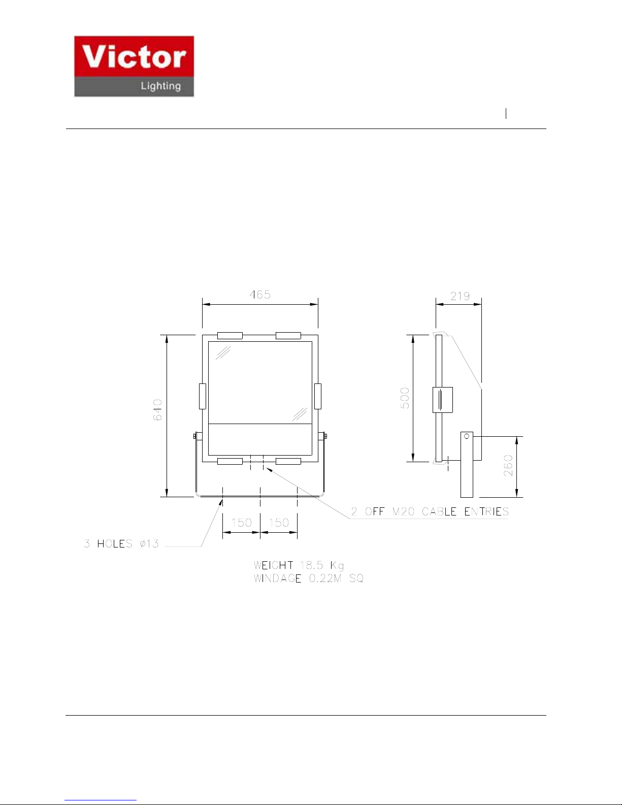
The VL71 Floodlight is designed for all round lighting applications. It is suitable for use with tubular discharge lamps and
single ended tungsten halogen lamps. A gear box is used with the low voltage range of 400w HID versions.
The floodlight is restricted in its mounting position. The beam of the floodlight may be aimed at any angle but the control gear
must always be mounted on or below the axis of rotation of the floodlight.
The floodlight is designed to be safe in normal operation.
The floodlight should not be used in conditions where there are environmental, vibration or shock conditions above the normal
for fixed installations.
The gaskets should not be exposed to hydrocarbons in liquid or high concentration vapour states.
The floodlight is suitable for applications where category 3 apparatus is used. The application is for ignitable gas and dust
atmospheres. The floodlight is not suitable for portable applications.
Note : Lamp ranges and temperature ratings are outlined in TABLE 0.
2.0 Storage
Luminaires and control gear boxes are to be stored in cool dry conditions preventing ingress of moisture and condensation.
3.0 Installation and Safety
3.1 General
There is no health hazards associated with this product whilst in normal use. However, care should be exercised during the
following operations. Installation should be carried out in accordance with (IECEx) EN 60079-14 or the local hazardous area
code of practice, whichever is appropriate.
In the UK the requirements of the 'Health and Safety at Work Act' must be met.
VL71 IOM IECEx ATEX Issue 02 May 08 2

IOM – VL71 FLOODLIGHT
Handling and electrical work associated with this product to be in accordance with the 'Manual Handling Operations
Regulations' and 'Electricity at Work Regulations, 1989'. Your attention is drawn to the paragraphs (i) 'Electrical Supplies', (ii)
'Electrical Fault Finding and Replacement' and (iii) 'Inspection and Maintenance'.
The floodlights are Class 1 and should be effectively earthed.
The luminaires are quite heavy and suitable means of handling on installation must be provided.
Certification details on the rating plate must be verified against the application requirements before installation.
The information in this leaflet is correct at the time of publication. The company reserves the right to make specification
changes as required.
3.1.1 Use in Combustible Dust Atmospheres
Where the equipment is used in ignitable dust atmospheres reference must be made to the selection and
installation standards in order that the equipment is used correctly. In particular this applies to the de-rating of
surface temperature for use where dust clouds may be present. Dust layers should not be allowed to
accumulate
on the fitting surface and good housekeeping is required for safe operation. Dust in layers has the potential to
form ignitable clouds and to burn at lower temperatures.
Refer to EN 61241-14 for additional details of selection, installation and maintenance.
3.1.2 Hybrid Mixtures – Gas plus Dust.
Where Hybrid mixtures exist as defined in EN 1127 as a potentially explosive atmosphere, consideration should
be given to verifying that the maximum surface temperature of the luminaire is below the ignition temperature of
the hybrid mixture.
3.1.3 Floodlight Orientation in the presence of combustible dust.
The luminaire was tested in accordance with (IECEx) EN 61241-1, (IECEx) EN 61241-0 practice A.
As the build up of the dust layer can never be guaranteed not to occur, the luminaire must not be mounted in an
orientation where the dust could lie on the glass. The temperature on the glass is the hottest point on the
luminaire and any obstruction of the radiation from the luminaire would cause the surface temperature to
increase.
3.2 Tools
A cross head screwdriver blade to open hinged cover.
3mm and 5mm flat blade screwdriver.
Suitable spanners for installing cable glands.
Pliers, knife, wire strippers/cutters.
3.3 Electrical Supplies
The supply voltage and frequency should be specified when ordering. A maximum voltage variation of +6%/-6% on the
nominal is expected. (The safety limit for T rating is +10%). Luminaires should not be operated continuously at more than
+6%/-10% of the rated supply voltage of the control gear or tapping. The user must determine the actual underlying site
supply and purchase or adjust accordingly. Care must be taken in connecting to the nominal 230V UK public supply. In
most cases, the luminaire has multi-tapped control gear which can be set to a range of voltages on 50 or 60Hz cycles. The
tappings are shown on the control gear and the limits are shown on the rating plate. If the equipment is located in high or low
voltage sections of the system, an appropriate voltage tap should be selected, but care must be taken to log or mark the
equipment so that the tapping is re-set if the equipment is re-located. If in doubt, tappings should be set on the high side,
10V max. drop is desirable for HPS. The light output will be reduced. The HPS circuits use S.I.P ignitors and the circuit
diagram will indicate the choke connections. Where MBI/Metal Halide lamps are used, the tapping must be set accurately for
best performance. Where shore or construction site supplies are used, different to the service supplies, tappings should be
re-set. If not, advice on the effect of these temporary supplies should be sought from the Technical Department. Where
adverse system conditions occur, luminaires can be supplied without PFC. The circuit current will then be the lamp current.
The circuit power does not change. Tungsten Halogen lamps must be selected for the supply voltage. Running at over the
rated supply voltage will reduce life and at greater than +10% will compromise the T rating.
VL71 IOM IECEx ATEX Issue 02 May 08 3
 Loading...