

Page 1
1
1.1.1.
Safety
Safety
Safety
Information
Information
Information
T
o ensure the safety operation, the following signs are used only
as specified in this operation instruction.
Warning
Warning
Warning
A
warning shows that if the operation does not
comply with the following correct instruction, it is
possible to bring hazards to the user or cause
damage to the calibrator in use. The warning also
points out how to avoid the accidents.
! Caution
Caution
Caution
A
caution shows that if the operation does not
comply with the following correct instruction, it is
possible to cause damage to the calibrator in use.
The caution also points out how to avoid
maloperation.
Note
Note
Note
A
note serves as a sign to remind the user that he
must understand the correct operation of the
calibrator and its characteristics.
T
o prevent the user and the calibrator from any electric shock and
other hazards, it is necessary to observe the following regulation:
Warning
Warning
Warning
I t is not allowed to operate the calibrator at the working
field where there exists flammable gas or explosive gas or
vapor. It is very dangerous to operate the calibrator in
such a surrounding.
N ever apply more than 30V between any two terminals, or
between any terminal and earth ground.
! CCC
aution
aution
aution
DDD
isassembly
isassembly
isassembly
: No one is allowed to remove the split case
(top & bottom) of the calibrator except
professionals.
III
nnn
use
use
use
: The calibrator can ’ t perform both input and
Page 2

2
output simultaneously. No direct connection
can be made between both input and output.
MMM
aintenance
aintenance
aintenance
: Periodically wipe the case with a damp
cloth and detergent; do not use any
corrosive solvents.
Note
Note
Note
T
o keep the calibrator in a designed accuracy, it needs
warming up 5 minutes before it is put into operation.
I f any user requires a higher accuracy of the calibrator, the
user should make contact with the manufacturer.
I f
the
automatic
reference-junction
temperature compensation
of
the calibrator
deviates from its designed accuracy, the
user should make contact with our manufacturer.
Page 3

3
2.2.2.
Instrument
Instrument
Instrument
Panel
Panel
Panel
Layout
Layout
Layout
and
and
and
Function
Function
Function
EEE
xplanation
xplanation
xplanation
ofofof
LCD
LCD
LCD
Display
Display
Display
Area
Area
Area
o
utput value
setting key
output digit
select ke y
P ower Switch key
Input/Output
Switch key
RJ-ON
RJ-ON
RJ-ON
key
℃ ///
℉ S witching
key
FUN select key
RANG
RANG
RANG
select key
LCD display area
Lo
INPUT
RJ-ON
RJ-ON
RJ-ON
30V
MAX
Hi
°°°
C/C/C/
°°°
FFF
INPUT
INPUT
INPUT
OUTPUT
30V
MAX
Lo
Hi
RANG
RANG
RANG
FUN
FUN
FUN
THER MOCO UPL E
CALIBRATOR
I nput terminal
output terminal
Page 4
4
a) OUTPUT : Press the key 〔 INPUT/OUTPUT
INPUT/OUTPUT
INPUT/OUTPUT
〕 when the
symbol ‘ output’appears in the display, denoting
that the calibrator is in an output state.
b) INPUT : Press the key 〔 INPUT/OUTPUT
INPUT/OUTPUT
INPUT/OUTPUT
〕 when the
symbol ‘ input’appears in the display, denoting
that the calibrator is in an input state.
c) CAL : When this symbol appears in the display, the
calibrator is in a calibration state.
d) 0 FS: This symbol appears with the calibrator getting
into a calibration state, denoting that the zero
point or the full scale point is in calibration.
e) RJ- ON: When this symbol appears in the display, it
denotes that the calibrator performs the
operation of its reference junction compensation.
(See subsection 5.2)
f) : This symbol appears to show that the battery is
nearly used up and needs replacing now. (See
subsection 3.1)
g) : This symbol appears to show that the output
digits need setting now.
h) mV, ℃ , ℉ : These symbols appear to show that the unit of a
present input value or output value.
i) ON : This symbol appears to show that the signal of
input or output is in a turn-on state.
j) R, S, K, E, J,
T,
B, N: Each of these individual symbols show the
type of a thermocouple.
3.3.3.
Replacing
Replacing
Replacing
the
the
the
battery
battery
battery
Warning
Warning
Warning
T he test leads need removing and the power supply of the
calibrator must be shut off prior to replacing the battery.
3.1When
3.1When
3.1When
the
the
the
symbol
symbol
symbol
appears
appears
appears
ininin
the
the
the
display,
display,
display,
ititit
denotes
denotes
denotes
that
that
that
the
the
the
battery
battery
battery
isisis
nearly
nearly
nearly
used
used
used
upupup
and
and
and
needs
needs
needs
replacing
replacing
replacing
according
according
according
tototo
Page 5

5
the
the
the
following
following
following
steps:
steps:
steps:
1) R
emove
the test leads
and
turn
off
the
power
supply
of
the calibrator
.
2) R emove the holster from the calibrator. O pen the battery cover
at the back of the calibrator by unlocking it in the indicated
direction.
3) Replace the used-up battery with a new one. Put the battery
cover back and lock it in the indicated direction.
4) Put the holster back onto the calibrator.
4.4.4.
Power-On/Off
Power-On/Off
Power-On/Off
ofofof
Calibrator
Calibrator
Calibrator
4.1
4.1
4.1
Power-key
Power-key
Power-key
operation
operation
operation
Press the power key to turn on the power supply of the calibrator .
Then press it again to hold it in one second and the power
supply will be off. When the power supply is turned on, the
calibrator will start to make self-diagnosis internally and the full
screen is in display. After this, appropriate operation should be
carried out.
NNN
ote
ote
ote
PPP
ower-on
ower-on
ower-on
:
To
ensure the correct operation of the
calibrator
with
power on, it is good practice to turn off the power
supply pausing 5 seconds, and then restart the
calibration.
4.2
4.2
4.2
Automatic
Automatic
Automatic
power-off
power-off
power-off
B y the shipping time,
the
calibrator
is
set
for
automati
c power-off
function in the factory like this: In case there is no operation of
the calibrator within 10 minutes after power-on, it will cut off the
power
supply
automatically. However,
users can decide
whether
they want to use the function of the automatic power-off
or
not. The
setting can be done by themselves. (See section 7)
555
. Output
Output
Output
from
from
from
calibrator
calibrator
calibrator
T he output terminal of the calibrator produces a DC voltage set by
the user
or
produces an analog temperature signal from a thermo-
Page 6
6
couple.
! Caution
Caution
Caution
D o not apply any voltage to the output terminal during the operation.
If any improper voltage is applied to the output terminal, it will cause
damage to the circuit.
OOO
utput
utput
utput
Operation
Operation
Operation
Procedure
Procedure
Procedure
5.1
5.1
5.1
DCDCDC
voltage
voltage
voltage
output
output
output
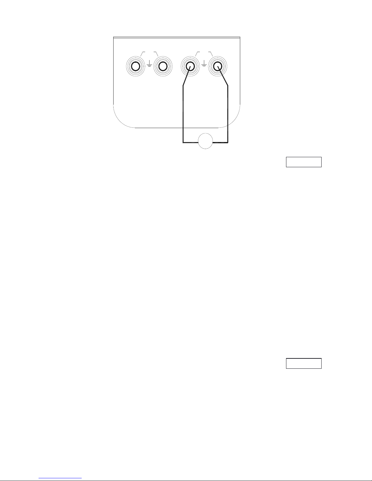
1) I nsert one end of the test lead into the output jack of the
calibrator and connect the other end to the input of the user ’ s
instrument as shown in the following diagram.
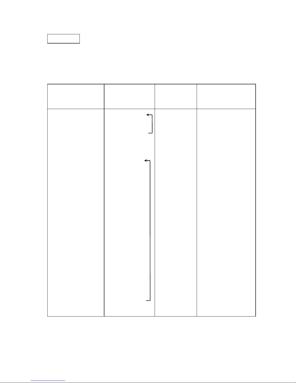
Func.Operation
Func.Operation
Func.Operation
Range
Range
Range
Operation
Operation
Operation
Display
Display
Display
Set
Set
Set
Range
Range
Range
DCV
DCV
DCV
1 V
TCTCTC
R
1 V
↓
100 mV
R
↓
S
↓
K
↓
E
↓
J
↓
T
↓
B
↓
N
0.0000V
000.00mV
0000 ℃
0000 ℃
0000.0 ℃
0000.0 ℃
0000.0 ℃
0000.0 ℃
400 ℃
0000.0 ℃
-0. 1 00 0 to 1 .1 000V
-10.00 to 110.00mV
-4 0 to 1760 ℃
- 20 to 1760 ℃
-200 to 1370 ℃
-200 to 1000 ℃
-200 to 1200 ℃
-2 00 to 400 ℃
400 to 1800 ℃
-200 to 1300 ℃
Page 7
7
2) P ress the key 〔 INPUT/OUTPUT
INPUT/OUTPUT
INPUT/OUTPUT
〕
when the symbol ‘ OUTPU T
’
appears in the display, denoting that the calibrator is in an
output state.
3) P ress the key 〔 FUN
FUN
FUN
〕 to select the V function when the unit ‘ V
’
appears in the display.
4) P ress the
key
〔 RANG
RANG
RANG
〕
to select the V
or
mV function when th e
unit ‘ V
’
or
‘ mV
’
appears in the display.
5)
P
ress the
key 〔
〕
/
〔 〕 to select the set digits for output.
6 ) Press the key 〔 〕 / 〔 〕 to change the numerical value of
the set digits. The value can do carry
or
number decrement
automatically. Hold the pressed key in one second and the
value will keep varying .
5.2
5.2
5.2
Simulating
Simulating
Simulating
output
output
output
from
from
from
thermocouple
thermocouple
thermocouple
1) I nsert one end of the test lead into the output jack of the
calibrator and connect the other end with the input of the
user ’ s instrument as shown in the above-illustrated diagram.
2) P ress the
key
〔 INPUT/OUTPUT
INPUT/OUTPUT
INPUT/OUTPUT
〕
when the
symbol
‘ OUTPU T
’
appears in the display, denoting that the calibrator is in an
output state.
3) P ress the
key
〔 FUN
FUN
FUN
〕
to select the thermocouple function whe n
the unit ‘ ℃
’
and the type ‘ R
’
appear in the display.
4) P ress the key 〔 RANG
RANG
RANG
〕 to select an appropriate type of a
thermocouple.
---
+++
MMM
OUTPUT
INPUT
30V
MAX
30V
MAX
Lo
Lo
Hi
Hi
Page 8

8
5) P ress the key 〔 〕 / 〔 〕 to select the set digits for output.
6) P ress the
key
〔
〕
/
〔
〕
to change the numerical value of t he
set digits. The value can do carry
or
number decrement
automatically. Hold the pressed key in one second and the
numerical value will keep varying.
7) A utomatic Compensation for Reference-Junction Temperature:
D uring the direct calibration of an instrument with reference-
junction temperature compensation, it is common practice to
press the key 〔 RJRJRJ
---
ONONON
〕 so that the calibrator can start the
function of automatic reference-junction compensation, thus
providing the required thermo-electromotive force for output
followed by displaying the symbol ‘ RJ-ON ’ .(Refer to section 8
concerning the reference-junction compensation accuracy of
the calibrator.)
Where:
Where:
Where:
output
output
output
emf
emf
emf
===
emf
emf
emf
corresponding
corresponding
corresponding
tototo
the
the
the
set
set
set
temperature
temperature
temperature
–––
emf
emf
emf
corresponding
corresponding
corresponding
tototo
the
the
the
room
room
room
temperature
temperature
temperature
...
I t takes two seconds for the calibrator to start its internal
reference junction compensation. A fter this, each
automatic compensation takes place at intervals of 10
seconds.
I f there is a change in the operating ambient temperature,
do not start the operation until the built -in compensating
sensor had become stable (ca.10 minutes).
I f there is no need for the calibrator to use the function of
automatic reference-junction compensation, the symbol
‘ RJ-ON
’
will no longer appear in the display by pressing the
key 〔 RJRJRJ
---
ONONON
〕 .
8) Press the key 〔 ℃ ///
℉ 〕 to select the unit ‘ ℃ ’
or
‘ ℉ ’ .
6.6.6.
Calibrator
Calibrator
Calibrator
Measurement
Measurement
Measurement
WWW
arning
arning
arning
D uring the operation, never apply more than 30V between any
two terminals,
or
between any terminal and earth ground. Any
Page 9

9
voltage more than 30V will not only cause damage to the
calibrator, but also lead to possible personal injury.
! Caution
Caution
Caution
D uring the operation, do not apply a voltage exceeding the
measuring range to the input terminal, which will cause possible
damage to the calibrator.
C onnect the calibrator to the instrument to be measured only
after the power supply of the instrument has been cut off. T he
electric connection without cutting off the power supply will lead
to possible damage to the calibrator.
D uring the operation, special care should be taken not to apply
current signals to the input terminal. Any improper electric
connection will cause damage to the calibrator and the
instrument to be measured.
6.1
6.1
6.1
Measuring
Measuring
Measuring
DCDCDC
voltage
voltage
voltage
1)
Insert one end of the test lead into the input jack of the
calibrator and connect the other end to the output of the user ’ s
instrument as shown in the following diagram:
2)
Press the key 〔 INPUT/OUTPUT
INPUT/OUTPUT
INPUT/OUTPUT
〕
when the symbol ‘ INPUT ’ , ‘ ON ’ ,
‘ mV
’
appears in the display, denoting
that the calibrator is in an input state.
3)
T he calibrator starts measurements
and display followed
by
indicating
‘ 000.00 ’ , denoting a wait. Then the
display indicates the measured re-
sult.
4)
The refreshing rate of displaying the measurement is about
twice per second. If the measured value exceeds the
measuring range, the display will indicate the symbol ‘ -OL- ’ .
6.2
6.2
6.2
Measuring
Measuring
Measuring
thermocouple
thermocouple
thermocouple
(TC)
(TC)
(TC)
+++
---
MMM
30V
MAX
30V
MAX
LoLo
Hi Hi
INPUT
OUTPUT
Page 10

10
1) I nsert one end of the test lead into the input jack of the
calibrator and connect the other end to the output of the user ’ s
instrument as shown in the above-illustrated diagram.
2) P ress the key 〔 INPUT/OUTPUT
INPUT/OUTPUT
INPUT/OUTPUT
〕
when the symbol ‘ INTPU T
’
appears in the display, denoting that the calibrator is in an
input state.
3) P ress the key 〔 FUN
FUN
FUN
〕
to select the function of measuring T C
when the display indicates the unit ‘ ℃ ’ and the type ‘ R ’ .
4) P ress the key 〔 RANG
RANG
RANG
〕 to select an appropriate type of TC.
5) When the display indicates the symbol ‘ 0000 ’ first, it denotes a
wait followed by displaying the measured result. The
refreshing rate of displaying the measurement is ca. once per
second. If the measured value exceeds the measuring range,
the display will indicate the symbol ‘ -OL- ’ .
6) A utomatic Compensation for Reference-Junction: press the
key 〔 RJRJRJ
---
ONONON
〕 to start the function of automatic reference
junction compensation. The measurement value is regard as a
temperature value through the reference junction compensation.
WWW
here:
here:
here:
temperature
temperature
temperature
indication
indication
indication
===
temperature
temperature
temperature
ofofof
TCTCTC
type
type
type
corresponding
corresponding
corresponding
tototo
input
input
input
emf
emf
emf
+++
room
room
room
temperature
temperature
temperature
7) P ress the key 〔 ℃ ///
℉ 〕 to select the unit ‘ ℃ ’
or
‘ ℉ ’ .
7.7.7.
Other
Other
Other
Features
Features
Features
T he following operation makes it possible for the calibrator to change
its automatic power-off function.
1) C ut off the power supply of the calibrator.
2) P ress the key 〔 POWER
POWER
POWER
〕 to make a full screen display. T hen
release
the
〔 POWER
POWER
POWER
〕
key immediately followed by pressing t he
key 〔 RANG
RANG
RANG
〕
when the calibrator gets into a maintenance stat e.
The display indicates the symbol ‘ AP-XX ’ .
3) P ress the key 〔 〕 when the symbol ‘ AP-OF ’ appears in the
display, denoting that there is no automatic power-off function
available to the calibrator, and when the symbol ‘ AP-ON
’
Page 11
11
appears, denoting that the calibrator has recovered its
automatic power-off function.
4) C ut off the power supply again to exit the maintenance state.
8.8.8.
Performance
Performance
Performance
Capabilities
Capabilities
Capabilities
OOO
utput
utput
utput
Function
Function
Function
&&&
Specification
Specification
Specification
(
applicable to temperature
range from 18 to 28 ℃ ,within one year after calibration).
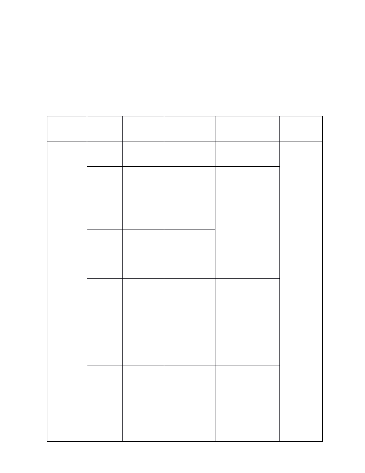
Output
Output
Output
Range
Range
Range
OOO
utput
utput
utput
Range
Range
Range
RRR
esolution
esolution
esolution
Accuracy
Accuracy
Accuracy
Remark
Remark
Remark
DCV
DCV
DCV
100mV
-10.00 to
110.00mV
0.01 mV
± 0.05 % of set
value ± 30 μ V
M ax.
output
current
± 2mA
1V
-0.10000
to
1.1000V
0.1 mV
± 0.05 % of set
value ± 0.3mV
TCTCTC
R
-40 to
1760 ℃
1 ℃
± 0.05 % of set
value
± 3 ℃ ( ≤ 100 ℃ )
± 0.05 % of set
value
± 2 ℃ (>100 ℃ )
B y using
ITS-90
t
emperature
scale
Note 1
Note 2
S
-20 to
1760 ℃
1 ℃
B
400 to
1800 ℃
1 ℃
± 0.05 % of set
value
± 3 ℃ (400 ℃ to
600 ℃ )
± 0.05 % of set
value
± 2 ℃ ( > 600 ℃ )
E
-200.0 to
1000.0 ℃
0.1 ℃
± 0.05 % of set
value
± 2 ℃ ( ≤ -100 ℃ )
± 0.05 % of set
value
± 1 ℃ ( > -100 ℃ )
K
-200.0 to
1370.0 ℃
0.1 ℃
J
-200.0 to
1200.0 ℃
0.1 ℃
Page 12

12
Input
Input
Input
function
function
function
&&&
Specification
Specification
Specification
(applicable to temperature
range from 18 to 28 ℃ ,within one year after calibration).
T
-200 to
400.0 ℃
0.1 ℃
N
-200.0 to
1300.0 ℃
0.1 ℃
III
nput
nput
nput
Range
Range
Range
III
nput
nput
nput
Range
Range
Range
Resolution
Resolution
Resolution
AAA
ccuracy
ccuracy
ccuracy
RRR
emark
emark
emark
DCV
DCV
DCV
100mV
-10.00 to
110.00mV
10 μ V
± 0.05 % of meas.
value ± 30 μ V
I nput resis.
1M Ω
TCTCTC
R
-40 to
1760 ℃
1 ℃
± 0.05 % of meas.
value ± 3 ℃ ( ≤ 100 ℃ )
± 0.05 % of meas.
value ± 2 ℃ (>100 ℃ )
B y using
ITS-90
temperature
scale
I nput resis.
1M W
Note 1
Note 2
S
-20 to
1760 ℃
1 ℃
B
400 to
1800 ℃
1 ℃
± 0.05 % of meas.
value ± 3 ℃ (400 ℃ to
600 ℃ )
± 0.05 % of meas.
value ± 2 ℃ (>600 ℃ )
E
-200.0 to
1000.0 ℃
0.1 ℃
± 0.05 % of meas.
value ± 2 ℃ ( ≤ -100 ℃ )
± 0.05 % of meas.
value ± 1 ℃ (>-100 ℃ )
K
-200.0 to
1370.0 ℃
0.1 ℃
J
-200.0 to
1200.0 ℃
0.1 ℃
T
-200.0 to
400.0 ℃
0.1 ℃
N
-200.0 to
1300.0 ℃
0.1 ℃
Page 13

13
N ote 1: The accuracy does not include the error of internal
temperature compensation caused by a sensor. The range of
the internal
temperature compensation
sensor
is
from -10
to
50 ℃
with its compensating error up to 0.5 ℃ .
N ote 2: temperature coefficient: ± 0.005 % of range per ℃ for the
temperature ranges from 0 to 18 ℃
and from 28 to 50 ℃ .
GGG
eneral
eneral
eneral
Specifications
Specifications
Specifications
P ower supply: 9V battery (
ANSI
/
NFDA 1604A
or
IEC6LR619V alkaline)
B attery life: ca.25 hours
M ax. permitted voltage: 30v (between any two terminals
or
between any terminal and earth ground )
O perating temperature: 0 ℃ to 50 ℃
O perating relative humidity: ≤ 80 ﹪ RH
S torage temperature: ≤ -10 ℃ to 55 ℃
S torage humidity: ≤ 90 ﹪ RH
S ize: 200 × 100 × 40 mm(with holster)
W eight: 550g (with holster)
A ccessory: operation instruction, a set of CF-36
industrial test lead (with alligator clips)
O ption: AC power-supply adapter (VCPS) and
a set of CF-31-A industrial test lead
(with probe clips)
Safety: Certified as compliant to IEC1010
provisions (Safety Standard issued by
International Electro technical
Commission
)
9.9.9.
CCC
alibration
alibration
alibration
NNN
ote
ote
ote
T
o ensure the designed accuracy of the calibrator, it is
Page 14

14
recommendable to calibrate your calibrator once a year. T he
following recommended standard equipment is used to perform the
calibration, which serves as an example.
! CCC
aution
aution
aution
D uring the operation, never apply more than max. permitted
voltage to the input of the calibrator, otherwise the overvoltage will
lead to possible damage to the input section.
D uring the operation, avoid any short circuit and never apply more
than the max. permitted voltage to the output of the calibrator and
the coworking standard device, otherwise any maloperation will
cause possible damage to their internal circuits.
9.1
9.1
9.1
Selecting
Selecting
Selecting
Standard
Standard
Standard
Equipment
Equipment
Equipment
CCC
aaa
librating
librating
librating
Output
Output
Output
Characteristics
Characteristics
Characteristics
CCC
alibrating
alibrating
alibrating
Input
Input
Input
characteristics
characteristics
characteristics
9.2
9.2
9.2
Ambient
Ambient
Ambient
Condition
Condition
Condition
for
for
for
Calibration
Calibration
Calibration
Ambient temperature: 23 ℃± 1 ℃
R elative humidity: 45 to 75% RH
W arming-up:
The standard equipment must be
warmed up to the given time.
D o not connect the calibrator to the
CCC
alib.Item
alib.Item
alib.Item
SSS
tandard
tandard
tandard
Equipment
Equipment
Equipment
Input
Input
Input
Range
Range
Range
Accuracy
Accuracy
Accuracy
Recommend
Recommend
Recommend
DCV
DCV
DCV
100mV
1V
D igital meter
M ax.110mV
M ax.1.1V
± (10ppm+1 μ V)
± (10ppm+5 μ V)
1281(FLUKE)
5520A( FLUKE)
or equivalent
CCC
alib.Item
alib.Item
alib.Item
SSS
tandard
tandard
tandard
Equipment
Equipment
Equipment
Output
Output
Output
Range
Range
Range
Accuracy
Accuracy
Accuracy
Recommen
Recommen
Recommen
ddd
DCV
DCV
DCV
100mV
standard
source
M ax.110mV
± (11ppm+2 μ V)
5520A(FLUKE)
or equivalent
Page 15
15
power supply until it has been exposed to
the ambient condition for 24 hours. T hen
set
the
calibrator to
a
state
of non-automatic
shutdown
followed by
warming up
to
0.5
hour.
NNN
ote
ote
ote
PPP
ower
ower
ower
supply
supply
supply
for
for
for
calibration:
calibration:
calibration:
During the calibration, the battery
needs replacing with a new alkaline
one.
9.3
9.3
9.3
Operation
Operation
Operation
Output
Output
Output
Calibration
Calibration
Calibration
O perating calibration in order of items and calibration points in the
following table:
9.3.1
9.3.1
9.3.1
1V1V1V
Range
Range
Range
Calibration
Calibration
Calibration
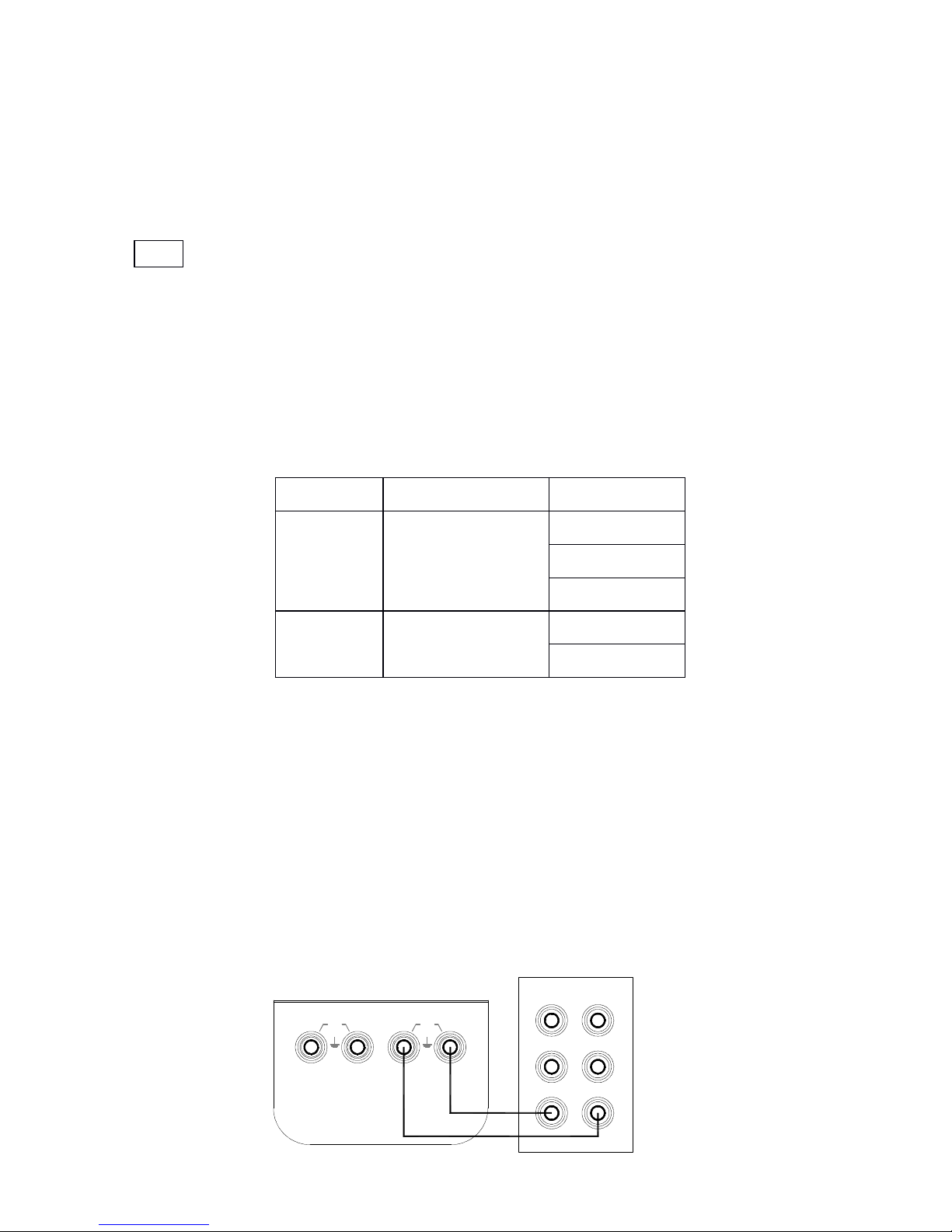
1) T he calibration writing is shown in the following diagram:
III
tem
tem
tem
No.
No.
No.
Output
Output
Output
Range
Range
Range
Calib.Point
Calib.Point
Calib.Point
1
DCV/1V
0
FS
0 FS
2
DCV/100mV
0
FS
OUTPUT
INPUT
Hi LoLo
30V
MAX
30V
MAX
Hi Lo
I-
I+
GUARD
Hi
digital meter1281 )
Page 16

16
2) . . . P ress the key 〔 FUN
FUN
FUN
〕 & 〔 RANGE
RANGE
RANGE
〕
first,
and then press the
key 〔 POWER
POWER
POWER
〕
to enter
the
calibrator in
a
state of calibrating t he
1V output when the display indicates the symbols
‘ OUTPUT ’ , ‘ CAL 0 ’ , ‘ ON
’
and the unit ‘ V ’ .
3) S et the digital meter to an appropriate range.
4) W ith the output stabilized, operate the keys 〔 〕 / 〔 〕 and
〔
〕
/
〔
〕
to set the indication of the calibrator in identity with
the reading of the digital meter.
5) P ress the key 〔 ℃ ///
℉
〕
and the display will flash, denoting tha t
the calibrated point has been stored.
6) P ress the key 〔 RANG
RANG
RANG
〕 to display the symbol ‘ CAL FS ’ . With
the output stabilized, repeat the operation of steps 4 and 5.
7) P ress the
key
〔 RANG
RANG
RANG
〕
to display the symbol ‘ CAL 0 FS ’ . Wit h
the output stabilized, repeat the operation of steps 4 and 5.
NNN
ote
ote
ote
CCC
alibration
alibration
alibration
storage:
storage:
storage:
Press the key 〔 ℃ ///
℉ 〕 to store the
calibrated point when the display does
not flash, denoting that the calibration
storage is invalid.
9.3.2
9.3.2
9.3.2
100mV
100mV
100mV
Range
Range
Range
Calibration
Calibration
Calibration
1) T he calibration wiring is shown in the above-illustrated
diagram.
2) Press the
key
〔 FUN
FUN
FUN
〕
to enter the calibrator in a state of 100m V
output calibration when the display indicates the symbols
‘ OUTPUT ’ , ‘ CAL 0 ’ , ‘ ON
’
and the unit ‘ mV ’ .
3) R epeat the operation of steps 3 to 6 in subsection 9.3.1
9.4
9.4
9.4
Operating
Operating
Operating
Input
Input
Input
Calibration
Calibration
Calibration
O perating the calibration in order of items and calibration
points in the following table:
Item
Item
Item
.No
.No
.No
III
nput
nput
nput
Range
Range
Range
CCC
alib
alib
alib
.Point
.Point
.Point
Page 17

17
9.4.1
9.4.1
9.4.1
100mV
100mV
100mV
Range
Range
Range
calibration
calibration
calibration
1)
T he calibration wiring is shown in the following diagram:
2)
P ress the key 〔 INPUT/OUTPUT
INPUT/OUTPUT
INPUT/OUTPUT
〕 to enter the calibrator in a
state of 100mV input calibration when the display indicates the
symbols ‘ INPUT ’ , ‘ CAL 0 ’ , ‘ ON ’ , and ‘ 100.00mV ’ .
3)
Set the standard source to a corresponding range.
4)
S et the output of standard source to the indication of the
calibrator. With the output stabilized, press the key 〔 ℃ ///
℉
〕
a nd
the display will flash, denoting that the calibrated point has
been stored.
101010
...
Points
Points
Points
for
for
for
Attention
Attention
Attention
tototo
Use
Use
Use
ofofof
Operation
Operation
Operation
Instruction
Instruction
Instruction
T he present operation instruction is subject to change without
notice.
T he content of the operation instruction is regarded as correct.
Whenever any user finds its mistakes, omission, etc., he
or
she
is requested to make contact with the manufacturer .
T he manufacturer is not liable for any accident and hazard
arising from any maloperation.
T he functions described in this operation instruction should not
be used as grounds to apply this product to a particular purpose.
1
DCV/100mV
FS:100mV
TRIG
OUT
Lo
OUTPUT
INPUT
SCOPE
Hi
NORMAL AUX
30V
MAX
30V
MAX
Lo
Lo Hi
Hi
standard source ( 5520A )
Page 18

18
MB-0002-01
 Loading...