

Page 1

USE AND MAINTENANCE MANUAL
MR 60B
ED. 06-2010 EN
Page 2

The descriptions contained in this document are not binding.
The company therefore reserves the right to make any modifications at any time
to elements, details, or accessory supply, as considered necessary for
reasons of improvement or manufacturing/commercial requirements.
The reproduction, even partial, of the text and drawings contained in this
document is prohibited by law.
The company reserves the right to make any technical and/or supply
modifications. The images are shown as reference only and are not binding as
to the actual design and/or equipment.
Symbols used in the manual
Open book symbol with an "i":
Indicates that this document is an instruction manual
Open book symbol:
Used to tell the operator to read the manual before using
the machine
Warning symbol
Carefully read the sections marked with this symbol, for
the safety of the operator and the machine:
Page 3

3
CONTENTS
CONTENTS ..................................................................................................................................................................3
ON CONSIGNMENT OF THE MACHINE ....................................................................................................................5
INTRODUCTORY COMMENT .....................................................................................................................................5
SERIAL NUMBER PLATE ...........................................................................................................................................5
TECHNICAL DESCRIPTION .......................................................................................................................................5
SYMBOLS USED ON THE MACHINE ........................................................................................................................6
SYMBOLS USED IN THE MANUAL............................................................................................................................7
GENERAL SAFETY REGULATIONS..........................................................................................................................8
MACHINE PREPARATION..........................................................................................................................................9
1. INTENDED USE ..................................................................................................................................................................... 9
2. HANDLING THE PACKED MACHINE ....................................................................................................................................9
3. HOW TO UNPACK THE MACHINE........................................................................................................................................ 9
4. FITTING THE BATTERIES INTO THE MACHINE................................................................................................................ 10
5. BATTERY AND BATTERY CONNECTOR CONNECTION .................................................................................................. 10
6. BATTERY CHARGER CONNECTION (only versions without CB) ....................................................................................... 11
7. RECHARGING THE BATTERIES......................................................................................................................................... 11
8. TYPE OF BATTERY ............................................................................................................................................................. 12
9. BATTERY MAINTENANCE AND DISPOSAL ....................................................................................................................... 12
10. BATTERY CHARGE LEVEL INDICATOR .......................................................................................................................... 13
11. ASSEMBLING THE SQUEEGEE ....................................................................................................................................... 13
12. SQUEEGEE INCLINATION ................................................................................................................................................ 13
13. ADJUSTING THE SQUEEGEE SUPPORT HEIGHT..........................................................................................................13
14. DISC BRUSH ASSEMBLY ................................................................................................................................................. 14
15. SOLUTION AND RECOVERY TANK ................................................................................................................................. 14
16. DETERGENT SOLUTION .................................................................................................................................................. 15
17. EMPTY SOLUTION TANK DEVICE ................................................................................................................................... 15
WORK.........................................................................................................................................................................16
PREPARING TO WORK........................................................................................................................................................... 16
OVERFLOW DEVICE ............................................................................................................................................................... 17
TRACTION ............................................................................................................................................................................... 17
BRAKES ................................................................................................................................................................................... 17
ACOUSTIC ALARM .................................................................................................................................................................. 18
FLASHING LIGHT (on request) ................................................................................................................................................ 18
AT THE END OF THE WORK....................................................................................................................................19
DAILY MAINTENANCE .............................................................................................................................................20
CLEANING THE RECOVERY TANK........................................................................................................................................ 20
CLEANING THE SQUEEGEE .................................................................................................................................................. 20
CLEANING THE SOLUTION TANK AND FILTER:................................................................................................................... 21
DISC BRUSH DISASSEMBLY ................................................................................................................................................. 21
WEEKLY MAINTENANCE.........................................................................................................................................22
CLEANING THE SUCTION TUBE............................................................................................................................................ 22
CLEANING THE SOLUTION TANK.......................................................................................................................................... 22
CLEANING THE RECOVERY TANK........................................................................................................................................ 22
EXTRAORDINARY MAINTENANCE.........................................................................................................................23
REPLACING THE FRONT SQUEEGEE RUBBER................................................................................................................... 23
REPLACING THE REAR SQUEEGEE RUBBER ..................................................................................................................... 23
REPLACING THE BASE SPLASH GUARD ............................................................................................................................. 23
TROUBLESHOOTING ...............................................................................................................................................24
INSUFFICIENT WATER ON THE BRUSHES .......................................................................................................................... 24
THE SQUEEGEE DOES NOT DRY PERFECTLY ................................................................................................................... 24
THE MACHINE DOES NOT CLEAN WELL.............................................................................................................................. 24
EXCESSIVE FOAM PRODUCTION ......................................................................................................................................... 24
THE SUCTION MOTOR DOES NOT FUNCTION .................................................................................................................... 25
THE BRUSH MOTOR DOES NOT WORK ............................................................................................................................... 25
IT IS IMPOSSIBLE TO RAISE OR LOWER THE BASE OR SQUEEGEE ............................................................................... 25
Page 4

4
THE MACHINE DOES NOT START......................................................................................................................................... 25
ELECTRIC FUSES AND THERMAL CUT-OUTS ..................................................................................................................... 26
THE MACHINE DOES NOT REVERSE ................................................................................................................................... 26
CHOOSING AND USING THE BRUSHES................................................................................................................27
EC DECLARATION OF CONFORMITY ....................................................................................................................28
Page 5

5
On consignment of the machine
When the machine is consigned to the customer, an
immediate check must be performed to ensure all the
material mentioned in the shipping documents has been
received, and also to check the machine has not suffered
damage during transportation. If this is the case, the carrier
must ascertain the extent of the damage at once, informing
our customer service office. It is only by prompt action of this
type that the missing material can be obtained, and
compensation for damage successfully claimed.
Introductory comment
This is a scrubbing machine that is able to clean a wide variety
of types of flooring and types of dirt by using the mechanical
action of two disc or cylindrical brushes, depending on the
model, and the chemical action of a water-detergent solution.
As it advances, it also collects the dirt removed and the
detergent solution not absorbed by the floor.
The machine must be used only for this purpose.
Even
the best machines will only work well if used correctly and
read this instruction booklet carefully and re-read it
whenever difficulties arise while using the machine. If
necessary, remember that our assistance service
(organised in collaboration with our dealers) is always
available for advice or direct intervention.
Serial number plate
TECHNICAL DESCRIPTION UM MR 60B
Working width mm 610
Squeegee width mm 780
Work capacity, up to m2/h 3660
Disk brush No. / Ø mm 1 / 610
Brush rotations rpm 170
Brush motor V/W 24 / 450
Pressure on the brushes kg 30
Traction motor V/W 24 / 400
Traction wheel Ø mm 220
Forward speed km/h 0 6
Maximum gradient with full load % 10
Suction motor V/W 24 / 310
Suction vacuum mbar 160
Rear elastic wheels Ø mm 300x70
Solution tank l 110
Recovery tank l 125
Steering diameter mm 1910
Machine length mm 1495
Machine height mm 1320
Machine width (without squeegee)
mm 680
Battery compartment (l x L x h) mm 384x520x340
Rated battery voltage V 24
Battery weight (max) kg 136
Machine weight (empty and without batteries) kg 223
Machine weight in running order (machine + batteries + water + operator) kg 544
Noise level (in compliance with IEC 704/1) dB (A)
Hand vibration level m/s
2
Body vibration level m/s
2
Page 6

6
SYMBOLS USED ON THE MACHINE
Main switch symbol (key switch)
Used on the instrument panel, to indicate the key switch for machine operation on (I) or off (O)
Base/squeegee movement symbols
Used to indicate the movement linkage of the base and squeegee
Symbol denoting battery electric charging
Pedal labels that indicate the forward and reverse direction of the machine
Used to indicate the direction of the machine
Symbol denoting acoustic alarm
Used to indicate the acoustic alarm button
Water quantity adjustment symbol
Used on the steering column to indicate the knobs for adjusting the quantity of water distributed on the
brushes
Parking brake symbol
Used to indicate the machines brake lever
Indicates the maximum gradeability
Page 7

7
SYMBOLS USED IN THE MANUAL
Indicates a dangerous situation
Indicates danger of gas exhalation and leakage of corrosive liquids
Indicates the danger of fire
Keep naked flames at a safe distance
Indicates to lift and move loads with lifting and transport means suitable for the mass and size
Page 8

8
GENERAL SAFETY REGULATIONS
The regulations below must be carefully followed in order to avoid harm to the operator and damage to the machine.
Read the labels on the machine carefully. Do not cover them for any reason and replace them immediately if they become damaged.
The machine must be used exclusively by authorised and trained personnel.
During the working of the machine, pay attention to other people and especially to children.
The machine is not suitable for cleaning carpets.
Do not mix different types of detergent as this may produce harmful gases.
Do not place any liquid containers on the machine.
The storage temperature must be between -25°C and +55°C; do not store outdoors in damp conditions.
Conditions of use: room temperature between 0°C and 40°C with relative humidity between 30 and 95%
Do not use the machine in an explosive atmosphere.
Do not use the machine as a means of transport.
Do not use acid solutions that could damage the machine and/or harm people.
Avoid working with the brushes when the machine is standing still, so as not to damage the floor.
Do not vacuum inflammable liquids.
Do not use the device to collect dangerous powders.
In the event of a fire, use a powder extinguisher. Do not use water.
Do not knock against shelving or scaffolding, where there is a danger of falling objects. Use protective devices (helmet).
Adapt the speed to the adhesion conditions.
Do not use the machine on surfaces with an inclination greater than the one shown on the plate.
When the machine is in parking mode, remove the key and insert the parking brake.
If you notice any damage to the battery charger cable, contact a FIMAP technical assistance centre immediately.
The machine is designed to carry out the washing and drying operations simultaneously. Different operations should only be
carried out in areas where the passage of unauthorised persons is prohibited. Signal the presence of damp floors with suitable
signs.
If the machine does not work properly, check this is not caused by failure to carry out routine maintenance. Otherwise, request
the intervention of the FIMAP technical assistance centre.
If you need to replace any components, request the ORIGINAL spare parts from a FIMAP dealer and/or Authorised Retailer.
Use original FIMAP brushes only indicated in the paragraph “CHOOSING AND USING THE BRUSHES".
In the event of danger, activate the emergency lever (connector placed under the operator's seat) immediately.
Before carrying out any maintenance work, switch off the machine and disconnect the battery connector.
Restore all electrical connections after any maintenance interventions.
Do not remove any protection devices which require the use of tools in order to be removed.
Do not wash the machine with direct water jets or with pressurised water, nor with corrosive substances.
Have the machine checked by a FIMAP assistance centre after at least every 200 hours of operation.
To prevent scaling in the solution tank filter, do not fill the tank with detergent solution many hours before using the machine.
Before using the machine, check that all the hatches and covers are positioned as shown in this Use and Maintenance Manual.
Make sure the recovery tank is empty before lifting.
When disposing of consumable materials, observe the laws and regulations in force.
The machine does not cause harmful vibrations.
When your FIMAP machine has reached the end of its long working life, dispose of the materials it contains (especially oils,
batteries and electronic components) in an appropriate manner, and bearing in mind that the machine itself was constructed
using 100% recyclable materials.
The batteries must be removed from the machine before its disposal.
The batteries must be disposed of in a safe manner, fully observing the laws and regulations in force.
The machine is not suitable for use by children and persons with reduced physical, mental and sensory capabilities, or people
who lack experience and knowledge.
Children must be supervised to ensure they do not play with the device.
Page 9

9
MACHINE PREPARATION
1. INTENDED USE
The scrubbing machine is designed exclusively for the professional cleaning of
surfaces and floors in industrial, commercial and public environments. In addition, only
use the machine in closed or at least covered environments.
2. HANDLING THE PACKED MACHINE
The machine is contained in specific packaging with a pallet for the handling with fork
trucks. The packages cannot be placed on top of each other.
The total mass of the machine with packaging is 240 kg (without batteries).
The dimensions of the packaging is as follows:
MR60 B
A: 1610mm
B: 730mm
C: 1600mm
A
C
B
3. HOW TO UNPACK THE MACHINE
1. Remove the outer packaging.
2. The machine is fixed to the pallet with wedges which block the wheels.
3. Remove the wedges.
4. Use a chute to get the machine down from the pallet, pushing it backwards.
5. Keep the pallet for any future transport needs.
Page 10

10
MACHINE PREPARATION
4. FITTING THE BATTERIES INTO THE MACHINE
The batteries must be housed in the special compartment beneath the recovery tank.
They should be handled using lifting equipment that is suitable in terms of both weight
and hook-up system. They must also satisfy the requirements of Standard CEI 21-5. The
dimensions of the battery compartment are: 384 x 520 x H340 mm.
WARNING: For battery maintenance and daily recharging, you
must fully respect the indications provided by the manufacturer or
retailer. All installation and maintenance operations must be
carried out by specialized personnel.
To insert the batteries you must:
1. Lock the machine engaging the brake lever.
2. Make sure that the recovery tank is empty.
3. Grip the handle under the seat to open the recovery tank.
4. Lift the recovery tank until it hooks to the end of the safety clamp.
5. Position the batteries.
ATTENTION: You are advised to only lift and move the batteries
with lifting and transportation means suitable for the specific
weight and size.
ATTENTION: You are advised to always wear protective gloves, to
avoid the risk of serious injury to your hands.
5. BATTERY AND BATTERY CONNECTOR CONNECTION
1. Connect the battery terminals as per the diagram shown in figure.
2. Connect the battery connector (1) to the machine connector (2).
Page 11

11
MACHINE PREPARATION
6. BATTERY CHARGER CONNECTION (only versions without CB)
The battery connector is found in the battery compartment by opening the recovery tank.
The connector (1), connected to the batteries, must be detached from machine
connector (2) and hooked up to the battery charger connector for charging. The
coupling connector is delivered in a bag inside the battery compartment, and must be
connected to the cables of the battery charger as indicated in the instructions (see the
battery charger manual).
ATTENTION: This process must be carried out by qualified
personnel. The incorrect or imperfect connection of the cables to
the connector can seriously harm people and damage objects.
7. RECHARGING THE BATTERIES
In order not to cause permanent damage to the batteries it is essential to avoid their
complete discharge: arrange the recharge within a few minutes of the switching on of
the flashing "discharged batteries" signal.
NOTE: Never leave the batteries completely flat, even if the machine is not being used.
Check the electrolyte level and top up with distilled water if necessary (batteries with
electrolyte fluid) every 10 charges.
WARNING: During recharging, keep the tank lifted and blocked with
the appropriate prop. Check the battery charger is suitable for the
batteries installed, in terms of both capacity and type
(lead/acid or GEL and equivalents). Never recharge GEL batteries
with an unsuitable battery charger. Follow the instructions given by
the battery/battery charger manufacturer with the utmost attention.
Danger of fire: Keep naked flames at a safe distance.
Danger of gas exhalation and leakage of corrosive liquids.
Page 12

12
MACHINE PREPARATION
8. TYPE OF BATTERY
To power the machine it is necessary to use:
- liquidelectrolyte lead traction batteries;
- sealed traction batteries with gas recombination or gel technology.
OTHER TYPES MUST NOT BE USED.
The batteries must meet the requisites laid out in standards CEI EN 60254-1:2005-12
(CEI 21-5) + CEI EN 60254-2:2008-06 (CEI 21-7).
The battery compartment can house up to four batteries.
For a good operating performance, we suggest the use of four 6V/210 Ah C5 batteries
9. BATTERY MAINTENANCE AND DISPOSAL
For maintenance and recharging, respect the instructions provided by the battery
manufacturer.
Particular attention must be paid when choosing the battery charger, if not supplied,
since there are different kinds according to the type and capacity of the battery.
When the battery reaches the end of its working life, it must be disconnected by expert,
trained personnel, then lifted (using the grips and suitable lifting devices) to remove it
from the battery compartment. EXHAUSTED BATTERIES ARE CLASSIFIED AS
DANGEROUS WASTE AND MUST BE CONSIGNED TO THE AUTHORISED BODIES
FOR CORRECT DISPOSAL.
WARNING: You are advised to always wear protective gloves, to
avoid the risk of serious injury to your hands.
WARNING: You are advised to only lift and move the batteries
with lifting and transportation means suitable for the specific
weight and size.
Page 13

13
MACHINE PREPARATION
10. BATTERY CHARGE LEVEL INDICATOR
The battery indicator uses LEDs and has 8 positions (7 yellow - charged batteries, and
1 red - run down batteries).
WARNING: A few seconds after the red indicator light comes on,
the brush motor switches off automatically. With the remaining
charge it is possible to complete the drying process before
recharging
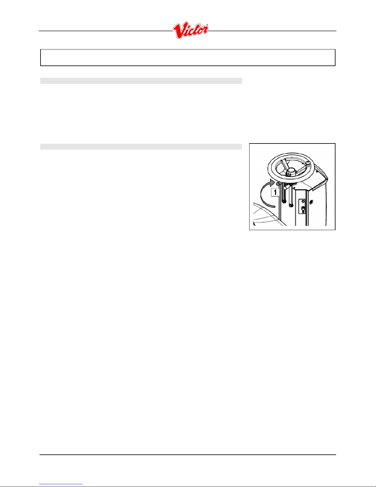
11. ASSEMBLING THE SQUEEGEE
For packaging reasons, the squeegee is supplied disassembled from the machine, and
must be assembled as shown in the figure.
Raise the squeegee connection by means of the left lever (1) turning it clockwise into the
vertical position.
Firstly insert the left pin (2) of the squeegee into the left slot on the arm and then the right
pin (3) into the right slot, being careful to keep the spring and the washer above
the arm’s flat bar. This can be simplified by first loosening the handwheel on the pin.
Then retighten the handwheel to block the squeegee in place.
Insert the squeegee tube in the appropriate sleeve (4).
12. SQUEEGEE INCLINATION
During working operation, the rear rubber is slightly tilted backwards (by about 5mm) in
a uniform way for its whole length.
If it is necessary to increase the bend of the rubber in the central part, you must tilt the
squeegee backwards, rotating the adjuster screw (1) clockwise.
13. ADJUSTING THE SQUEEGEE SUPPORT HEIGHT
The height of the squeegee must be adjusted on the basis of the state of wear and tear
of the rubber.
Carry out the following operations for adjustment:
unscrew the locking nut
raise or lower the wheel (1) by sliding it on the slot of the support
block it by tightening the locking nut once the required height is reached.
Note: To facilitate the operation, completely lower the squeegee and put a spacer of a
few millimetres (2 to 4 mm depending on the type of rubber) under the wheel.
Page 14

14
MACHINE PREPARATION
14. DISC BRUSH ASSEMBLY
1. Lift the base by turning the right lever (1) to move the base counterclockwise.
WARNING: During this operation, check there are no people or
objects near the brush.
2. With the base up, insert the brushes in the plate housing beneath the base, turning
them until the three pins enter the niches in the plate itself; turn the brush clockwise
until the pin is pushed towards the coupling spring and is locked into place.
WARNING: You are advised to always wear protective gloves, to
avoid the risk of serious injury to your hands.
15. SOLUTION AND RECOVERY TANK
Check correct position of the suction tube (1), that must be inserted in the fitting of the
squeegee.
Check that the knob of the cap on recovery tank drain pipe (2) on the back of the
machine is screwed on.
Check that the knob of the cap on solution tank drain pipe (3) on the left side of the
machine, is screwed on.
Page 15

15
MACHINE PREPARATION
16.DETERGENT SOLUTION
Fill with clean water at a temperature not exceeding 50°C. The solution tank can be filled
either through the opening (1) with a screw cap, or the rubber cap (2), which also supports
the water hose. If the supply is made via the rubber cap, unscrew the cap to allow the air to
vent correctly. Add the liquid detergent (3) into the solution tank, in the concentration and
manner specified by the manufacturer. The formation of excess foam could damage the
suction motor, so use only the minimum amount of detergent necessary.
Make sure the recovery tank is empty, otherwise empty it completely.
ATTENTION: Put on protective gloves before handling
acid/alkaline detergents or solutions, to avoid the risk of burning
your hands.
WARNING: Always use detergents whose manufacturer's label
indicates their suitability for scrubbing machines. Do not use acid
or alkaline products or solvents without this indication.
In addition, you are advised to always use low foam detergents.
Do not use pure acids or detergents with a stronger gradation than
that indicated on the label supplied.
17. EMPTY SOLUTION TANK DEVICE
To check the quantity of water in the solution tank there is a special level indicator tube
(5) next to the driver's seat.
Page 16

16
WORK
PREPARING TO WORK
1. Carry out the operations to prepare the machine.
2. Connect the connector to the batteries (1).
3. Sit on the driver’s seat.
4. Check the parking brake is released (2).
5. Turn the key of the main switch a quarter of a turn clockwise. Immediately, on the
instrument panel, the display will turn on indicating the charge level of the batteries.
6. Move the tap lever (3) downwards and adjust the amount of water required.
7. Lower the base by turning the right lever (4) clockwise, then lower the squeegee
turning the left lever (5) counterclockwise.
8. Pressing the accelerator pedal (6 - right pedal), the machine starts moving and the
brush will rotate.
9. To perform a reverse manoeuvre, lift the squeegee by turning the left lever (5)
clockwise, then press both pedals (6 and 7) and the machine will start moving
backwards.
During the first meters, check there is sufficient solution and that the squeegee dries
perfectly. The machine will start working in good working order up to run out of
detergent solution or until the battery is discharged.
Page 17

17
WORK
WARNING: If problems arise during operations, turn off the key, engage the parking
brake by pushing the lever (9) to the left until the machine brakes and release the
emergency lever placed below the operator. These commands block all moving
machine parts. Having resolved the problem, to start working again, reconnect the
connector, turn on the key and release the parking brake lever.
The machine will not start if the operator is not properly seated.
A flashing red warning light appears on the display when the battery charge level is
getting too low. The brush motor automatically turns off; batteries must be recharged
as soon as possible.
A residual charge remains so you can complete the drying operation and move the
machine to the recharging point.
OVERFLOW DEVICE
The machine is not equipped with an overfill device, because the capacity of the recovery
tank is greater than the capacity of the solution tank. In extreme cases, there
is a mechanical device (float) on the lid that closes the passage of air to the engine intake
protecting it when the recovery tank is full. In this case, turn the working knob to
transfer (movement of the machine without working), and the engine turns off after about
15-25 seconds. Then proceed with emptying the recovery tank through a special
drainage pipe (10).
It is good practice when restoring the level of the solution tank, to empty the recovery
tank through the special drainage pipe (10).
TRACTION
This machine is equipped with electronic traction control.
To move the machine, after having turned the key, push the drive pedal (11) adjusting
the speed by pressing the pedal more or less. The machine will then start moving.
To make a reversing manoeuvre, press both pedals (11 and 12) the machine will then
start moving backwards. During reverse motion, the machine emits an acoustic signal.
BRAKES
The machine has an electronic braking system. To brake, in normal conditions, just
remove your foot from the accelerator pedal. If the service brake does not operate
properly or in case of need (parking, danger, etc.) actuate the mechanical brake pedal
(13) by pushing it down and locking it by pulling the lever (14) to the left until the pedal
(13) is locked.
Page 18

18
WORK
ACOUSTIC ALARM
The machine is equipped with a buzzer controlled by button (15) on the right side of the
steering column.
FLASHING LIGHT (on request)
The machine is equipped for a flashing light that turns on automatically when the key in
the main switch is turned on.
Page 19

19
AT THE END OF THE WORK
At the end of the work, and before carrying out any type of maintenance, perform the
following operations:
1. Close the tap (1).
2. Lift the base by turning the right lever (2) counterclockwise, then lift the squeegee
turning the left lever (3) clockwise. The suction motor turns off after a few seconds.
3. Take the machine to the location designated for draining the water.
4. Turn the machine off by turning the key one quarter counterclockwise and remove it
from the panel.
5. Engage the parking brake.
WARNING: Before performing any maintenance, remove the keys
from the panel and disconnect the battery connector of the machine.
6. Disconnect the tube (4) from its seat, unscrew the drainage cap and empty the
recovery tank.
WARNING: This operation must be carried out using gloves to
protect against contact with dangerous solutions.
7. Slide the suction tube (5) from the squeegee sleeve.
8. Remove the squeegee (6) from the support arm by unscrewing the handwheel (7).
9. Clean well both the squeegee and the rubbers with a jet of water.
10. After cleaning the squeegee and rubbers, replace the squeegee on the initial
support, firstly inserting the left pin of the squeegee in the left slot of the arm, then
the right pin in the right slot, being careful to keep the spring and washer on the plate
of the arm. This can be simplified by first loosening the handwheel on the pin.
Then retighten the handwheel to block the squeegee in place.
11. Finally insert the squeegee tube in the special sleeve.
Page 20

20
DAILY MAINTENANCE
CLEANING THE RECOVERY TANK
1. Disconnect the tube (1) from its seat, unscrew the drainage cap and empty the
recovery tank.
WARNING: This operation must be carried out using gloves to
protect against contact with dangerous solutions.
WARNING: Before performing any maintenance, remove the keys
from the panel and disconnect the battery connector of the
machine.
2. Raise the cap (2) until the hook is secured to the prop (3) of the recovery tank.
3. Make sure to clean the filter inside the lid (4). To access the filter, remove the
protection of the intake filter turning it clockwise, remove it and clean it under
running water.
4. Clean and rinse the recovery tank and the suction pipe (connecting pipe between the
squeegee and the tank).
5. Reposition the cap on the drainage tube and lower the suction cap. To lock the prop
(3) just slightly raise the cap, release the prop (3) and lower the cap up to
close it.
CLEANING THE SQUEEGEE
The careful cleaning of the whole suction group ensures better drying and cleaning of the
floor as well as greater duration of the suction motor. Proceed as follows for cleaning:
1. Slide the suction tube (1) from the squeegee sleeve.
2. Remove the squeegee (2) from the support arm by unscrewing the handwheel (3).
3. Check the wear of the rubbers. If the edge of the rubber is ruined, the rear rubber can
be turned on all four corners. If the rubbers are completely worn proceed with
the replacement. To remove the rubber, turn the wing nuts (4) in a horizontal position,
remove the rubber-pressing blade (5) and then remove the rubber to turn it
or replace it.
4. Proceed in reverse to replace the rubber.
5. After cleaning, replace the squeegee (2) on the initial support, firstly inserting the left
pin of the squeegee in the left slot of the arm, then the right pin in the right slot,
being careful to keep the spring and washer on the plate of the arm. This can be
simplified by first loosening the handwheel (3) on the pin. Then retighten the
handwheel (3) to block the squeegee in place.
6. Finally insert the squeegee tube in the special sleeve.
WARNING: Before performing any maintenance, remove the keys
from the panel and disconnect the battery connector of the
machine.
Page 21

21
DAILY MAINTENANCE
CLEANING THE SOLUTION TANK AND FILTER:
1. Disconnect the clean water drainage pipe (1) from its housing on the left side of the
machine, unscrew the cap and empty the tank.
2. Remove the plug from the solution tank refill opening.
3. Rinse the inside of the tank with a jet of water.
4. Close the drainage pipe with the cap and put it in place.
5. Close the water tap (2).
6. Unscrew the filter (3) at the front of the machine.
7. Remove the internal filter cartridge and rinse everything thoroughly with running water.
8. Reassemble everything, repeating the above-mentioned operations in the reverse order.
WARNING: Before performing any maintenance, remove the keys
from the panel and disconnect the battery connector of the machine.
DISC BRUSH DISASSEMBLY
1. Lift the base by turning the right lever (1) to move the base counterclockwise.
WARNING: Before performing any maintenance, remove the keys
from the panel and disconnect the battery connector of the machine.
WARNING: During this operation, check there are no people or
objects near the brush.
2. Rotate the brush counterclockwise until it comes out of the brush-holder plate seat,
as shown in the figure.
WARNING: You are advised to always wear protective gloves, to
avoid the risk of serious injury to your hands.
Page 22

22
WEEKLY MAINTENANCE
CLEANING THE SUCTION TUBE
Whenever suction seems to be unsatisfactory, check that the suction tube (1) is not
obstructed. If necessary clean with a jet of water as follows:
1. Detach the aspiration tube from the seat on the recovery tank.
2. Clean it with a water jet introduced from the side where it is connected to the tank.
3. Reassemble everything, carrying out the above-mentioned operations in the
reverse order.
WARNING: This operation must be carried out using gloves to
protect against contact with dangerous solutions.
CLEANING THE SOLUTION TANK
At least once a week, it is necessary to carefully clean the solution tank in order to keep
the machine in perfect state:
1. Disconnect the clean water drainage pipe (1) from its housing on the left side of the
machine, unscrew the cap and empty the tank.
2. Remove the plug from the solution tank refill opening.
3. Rinse the inside of the tank with a jet of water.
4. Close the drainage pipe with the cap and put it in place.
5. Close the tank by placing the filter and the cap.
CLEANING THE RECOVERY TANK
1. Disconnect the tube (1) from its seat, unscrew the drainage cap and empty the
recovery tank.
WARNING: This operation must be carried out using gloves to
protect against contact with dangerous solutions.
2. Raise the cap (2) until the hook is secured to the prop (3) of the recovery tank.
3. Check the filter inside the cover (4) is clean and, if necessary, loosen the cover fixing
screws and carefully rinse the filter.
4. Clean and rinse the recovery tank and the suction pipe (connecting pipe between the
squeegee and the tank).
5. Reposition the cap on the drainage tube and lower the suction cap. To lock the prop (3)
just slightly raise the cap, release the prop (3) and lower the cap up to close it.
Page 23

23
EXTRAORDINARY MAINTENANCE
REPLACING THE FRONT SQUEEGEE RUBBER
Suction will be poor and the machine will not dry perfectly if the front squeegee rubber is
worn. Proceed as follows to replace:
1. Remove the squeegee from the support arm by unscrewing the handwheel.
2. Turn the wing nuts (1) in the horizontal position.
3. Remove the front rubber-pressing blades (2).
4. Remove the rubber (3) and replace it.
5. Proceed in reverse to replace the rubber.
REPLACING THE REAR SQUEEGEE RUBBER
If the squeegee rear rubber is worn and does not dry well, it is possible to change the
drying edge using one of the 4 edges of the rubber.
This operation can be done both with a squeegee fitted or removed as follows:
1. Turn the wing nuts (1) in the horizontal position.
2. Remove the rear rubber-pressing blades (2).
3. Remove the rubber (3) and replace it.
4. Proceed in reverse to replace the rubber.
5. Adjust the height of the squeegee depending on the rubber (see “ADJUSTING THE
HEIGHT OF THE SQUEEGEE SUPPORT”).
REPLACING THE BASE SPLASH GUARD
Periodically check the condition of the base casings that serve as protection to the
rotation of the brushes. To replace proceed as follows:
1. With the base lowered, remove the fixing screws of the casing to the base.
2. Remove the casing.
3. Fit the new casing with the screws previously removed.
WARNING: Before performing any maintenance, remove the keys
from the panel and disconnect the battery connector of the machine.
WARNING: The housing can prevent damage to persons or
property. Always check for wear.
Page 24

24
TROUBLESHOOTING
INSUFFICIENT WATER ON THE BRUSHES
1. Check there is water in the solution tank (1).
2. Check that the tap (2) is open.
3. Clean the solution filter located at the front of the machine.
THE SQUEEGEE DOES NOT DRY PERFECTLY
1. Check the squeegee is clean.
2. Check the regulation of the squeegee (see “MACHINE PREPARATION”).
3. Clean the entire suction unit (see “WEEKLY MAINTENANCE”).
4. Replace the rubbers, if worn.
THE MACHINE DOES NOT CLEAN WELL
1. Check the state of wear and tear of the brush and, if necessary, replace it. The brush
should be changed when the bristles are about 15mm high. For replacement
see "BRUSH DISASSEMBLY" and "BRUSH ASSEMBLY". Working with an overworn brush may cause damage to the floor.
2. Use a different kind of brush to the one fitted as standard. For cleaning floors where
the dirt is particularly resistant, we recommend the use of a special brush supplied
upon request and according to needs (see “CHOOSING AND USING THE
BRUSHES”).
EXCESSIVE FOAM PRODUCTION
Check that a low foam detergent has been used. If necessary, add a small quantity of
antifoam liquid to the recovery tank.
Remember that, when the floor is not very dirty, more foam is generated. In this case the
detergent solution should be more diluted.
Page 25

25
TROUBLESHOOTING
THE SUCTION MOTOR DOES NOT FUNCTION
1. Check whether the recovery tank is full and, if necessary, empty it.
2. Check the float switch on the suction cap (see also “CLEANING THE RECOVERY
TANK” in the chapter “DAILY MAINTENANCE”).
THE BRUSH MOTOR DOES NOT WORK
ATTENTION To avoid damaging the floor, the motor only starts up when the machine is
moved forwards.
1. Check that the base is lowered during the forward movement with the right lever (1)
turned clockwise.
2. The operator must be properly seated in the driving position.
3. Check no thermal protection device has intervened.
4. Check the correct connection of the motor to the terminal under the footboards.
IT IS IMPOSSIBLE TO RAISE OR LOWER THE BASE OR SQUEEGEE
The machine is fitted with electrical protection devices that control the base and
squeegee ascent/descent motor reducers. In the event of overloading, the fuses
interrupt the power supply. After checking and removing the reason for the problem, to
reset them just switch the machine off then on again. If the problem persists, contact
the FIMAP technical assistance centre.
THE MACHINE DOES NOT START
1. Check that connector (1) is connected to the batteries.
2. Check the key switch is ON/I.
3. Check that batteries (2) are charged.
Page 26
26
TROUBLESHOOTING
ELECTRIC FUSES AND THERMAL CUT-OUTS
In addition to general 80 A fuses, the machine is also fitted with self-restoring safety
fuses located on the boards in the electric system that interrupt the power supply to the
brush and suction motors when the machine exceeds the predetermined load. To restore
the power supply to the motor, switch off the machine and wait for the fuses to
cool down (about 40 seconds). If the switch disconnects the current again, contact the
FIMAP technical assistance centre.
THE MACHINE DOES NOT REVERSE
WARNING To avoid damage to the squeegee, the reverse movement is disabled and
only works when the squeegee is lifted.
1. Check that the squeegee is lifted during the reverse movement with the left lever (1)
turned clockwise.
2. The operator must be properly seated in the driving position.
3. Check no thermal protection device has intervened.
Page 27

27
CHOOSING AND USING THE BRUSHES
POLYPROPYLENE BRUSH (PPL)
Used on all types of floors. Good resistance to wear and tear, and hot water (no greater than 60°C). The Polypropylene brush is
non-hygroscopic and therefore retains its characteristics even when working in wet conditions.
NYLON BRUSH
Used on all types of floors. Excellent resistance to wear and tear, and hot water (even over 60°C). The nylon is hygroscopic and
so tends to lose its characteristics over time when working in wet conditions.
ABRASIVE BRUSH
The bristles of this type of brush are charged with highly aggressive abrasives. It is used to clean very dirty floors. To avoid floor
damage, work only with the pressure strictly necessary.
THICKNESS OF THE BRISTLES
Thicker bristles are more rigid and are therefore used on smooth floors or floors with small joints.
On uneven floors or those with deep joints, it is advisable to use softer bristles which can enter the gaps more easily.
Remember that when the bristles are worn and therefore too short, they will become rigid and are no longer able to penetrate and
clean deep down. In this case, like with over-large bristles, the brush tends to jump.
PAD HOLDER
The pad holder is recommended for cleaning shiny surfaces.
There are two types of pad holder:
1. The traditional pad holder is fitted with a series of anchor points that allow the abrasive floor pad to be held and dragged while
working.
2. The CENTRE LOCK type pad holder not only has anchor points, but also a snap-type central locking system in plastic that
allows the abrasive floor pad to be perfectly centred and held without any risk of it becoming detached. This type of holder is
especially suitable for machines with several brushes, where the centring of the grinding wheels is difficult.
TABLE FOR CHOOSING THE BRUSHES
Machine No. of brushes Code Type of bristles ØBristles Ø Brush Length Notes
MR - 60 1
405630
405629
405627
405628
405519
PPL
PPL
NYLON
TYNEX
(ABRASIVE)
PAD HOLDER
0.6
0.9
0.9
610
610
610
610
585 CENTRE LOCK
 Loading...