

VictelGlobal ALK300 series Operation Manual

ALK300 Series Transceiver
Operation Manual
Guangzhou VictelGlobal Communications Co., Ltd.
April, 2013

OUTLINE
1.1 Configuration .............................................................................................................. 3
1.2 Functions ..................................................................................................................... 4
1.3 Working Environment ................................................................................................. 5
1.4 Power Supply Adaptation & Power Consumption ...................................................... 5
2 Operation Instruction ............................................................................................................. 5
2.1 Introduction of Panels & Interfaces ............................................................................ 5
2.1.1 Front Panel of ALK300 Series Transceivers .................................................... 5
2.1.2 Back View of the ALK300 Series Transceiver ................................................. 9
2.2 Wiring Method .......................................................................................................... 11
2.3 Hopping ..................................................................................................................... 11
2.3.1 Coding Switch of the Transceiver .................................................................. 11
2.4 Power On the Equipment .......................................................................................... 13
3 NMS Settings ....................................................................................................................... 13
4 Maintenance ......................................................................................................................... 13
4.1 Installation Environment ........................................................................................... 13
4.2 Report & Solution of Equipment Failures ................................................................. 14
4.3 Equipment Usage ...................................................................................................... 14
4.4 Cleaning of the Equipment Surface .......................................................................... 14
4.5 Equipment Grounding ............................................................................................... 14
5 Transportation ...................................................................................................................... 14
6 Contact: ................................................................................................................................ 16
1.GeneralIntroduction
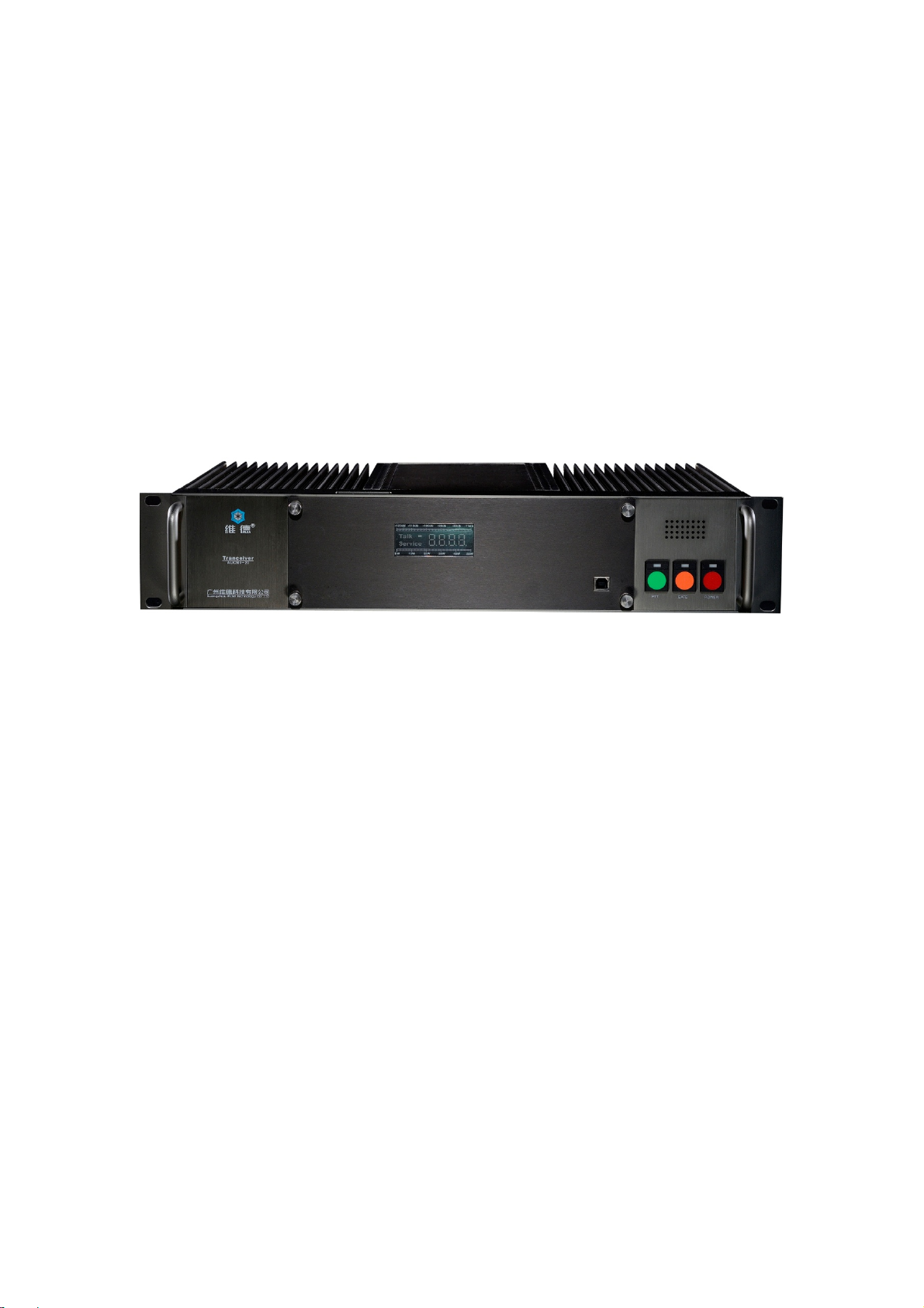
The ALK300 series transceiver of VictelGlobal adopts standard
19-inch 2U structure, fully modularized design and optimal design for
heat dissipation. The front panel is equipped with high-speed bus line for
connection between transceivers, the special wiring hole of which
facilitates the installation, test and maintenance and makes the whole unit
tidy. VictelGlobal has been granted the patent for structural design.
The ALK300 series transceiver adopts dual PA design, greatly
reducing the unit temperature, improving the unit stability and prolonging
the unit life. The two PAs can work separately as two PAs and work
altogether as backup for each other.
1.1 Configuration
The digital transceiver is consisted of digital Rx & Tx module,
power supply module, PA module, Carrier Control Module (CCM), hub
board, satellite module and bus line board etc., which are connected via
the bus line board.

1.2 Functions
z RF Transmission
The RF Tx module shall modulate the digitalized audio and
digital/analogue signalling generated by CCM to the RF signal and
then transmit it.
z RF Reception
The RF Rx module shall demodulate the digital/analogue signalling
and audio signals after receiving the wireless signal and then send
them to CCM for procession.
z Rx & Tx Information Display
The Rx field intensity and Tx power shall be displayed on the LED in
the front panel. Together with the use of management software, the
detailed parameters of the receiver and transceiver can be acquired.
z Local Audio
The local audio signal can be monitored via megaphone.
z Channel Cascading
Multiple transceivers can form one base station by connecting the
interface of each transceiver via high-speed bus line. Usually the 1
channel shall act as the control channel and all the rest channels shall
st
act as traffic channels, the quantity of which can be increased flexibly
by connecting more transceivers.
1.3 Working Environment
z Working temperature: -30℃~60℃
z Storage temperature: -40℃~85℃
1.4 Power Supply Adaptation & Power Consumption
z AC: 90~260V (45~55Hz)
z Power consumption: <350W
2 Operation Instruction
2.1 Introduction of Panels & Interfaces
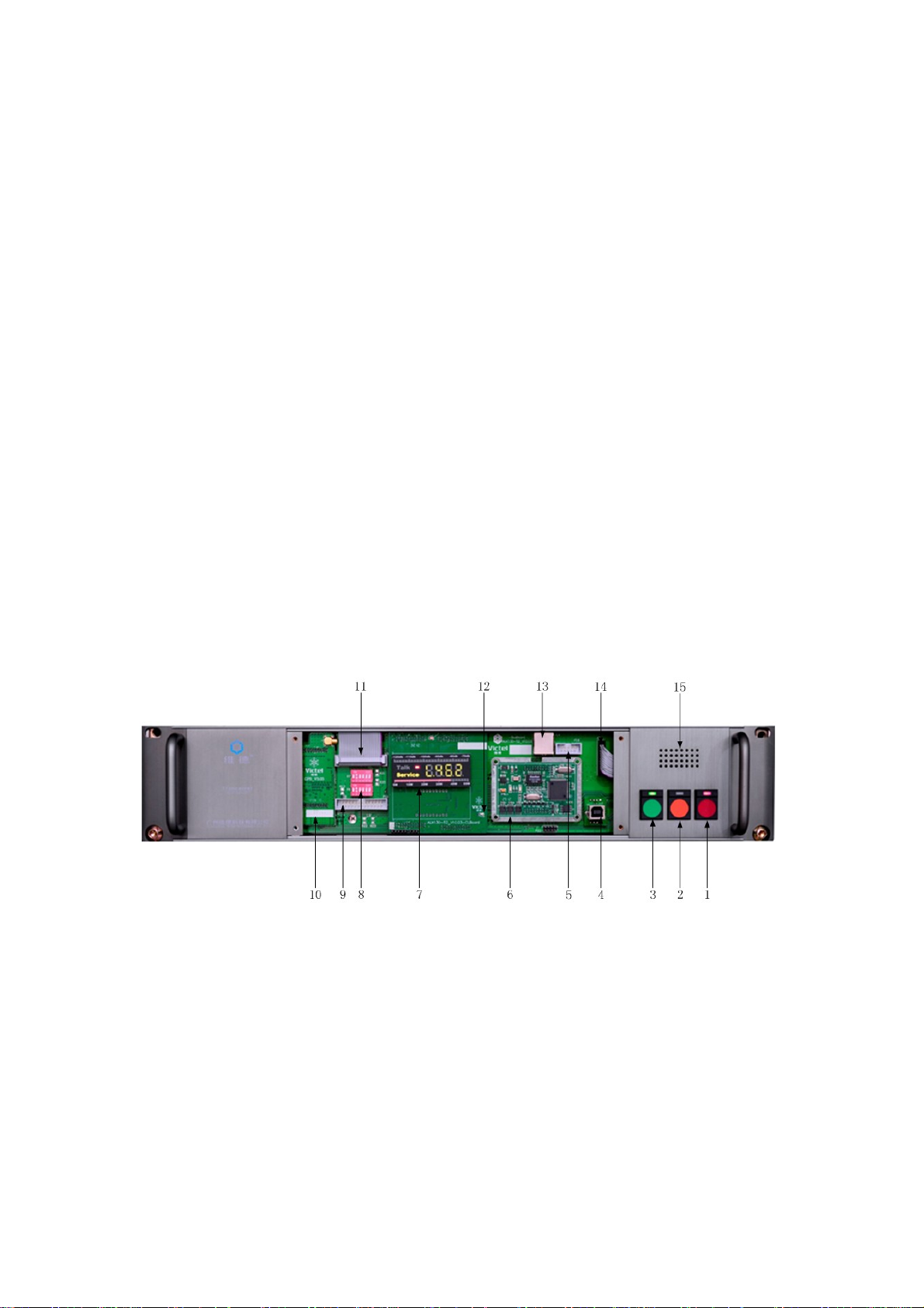
2.1.1FrontPanelofALK300SeriesTransceivers
1— Button of ‘POWER’ and Power Supply LED
Press the button ‘POWER’ to power on the transceiver with the
power supply LED turned on. Press the button ‘POWER’ when the
transceiver is under working status to power off the transceiver with the
power supply LED turned off.
2— Button of ‘GATE’ & Rx LED

Press the button ‘GATE’ to switch on the megaphone and the user
shall be able to monitor the audio information received by the receiver.
Press the button ‘GATE’ when the transceiver is under monitoring to
switch off the megaphone. The Rx LED shall be turned on when the
receiver receives valid signal, or it shall be turned off.
3— Button of ‘PTT’ & Tx LED
Press the button ‘PTT’ to activate the PA long Tx. The PA long Tx
can also be activated by touching the button ‘PTT’ twice. Touch the
button ‘PTT’ once again to stop the PA long Tx. The Tx LED shall be
turned on when the PA is under Tx status, or it shall be turned off.
4— Coordination Interface
The NMS shall do various operations to the transceivers via the
coordination interface, including data monitoring, parameter
configuration and software updation, etc.
5— CCM Programing Port
This interface is used for the writing of the programs to the CCM.
The ordinary users do not have access to the interface.
6— Carrier Control Module (CCM)
The CCM controls the work of the whole transceiver and processes
such core work as digital/analogue signaling and audio switch, etc.
7— Hub board
The hub board displays various status information of the transceiver,
 Loading...