

Page 1
I-VICFLEX.VS1INSTALLATION INSTRUCTIONS
Victaulic® VicFlex™ Style VS1 Dry Sprinkler
I-VICFLEX.VS1_1
REV_D
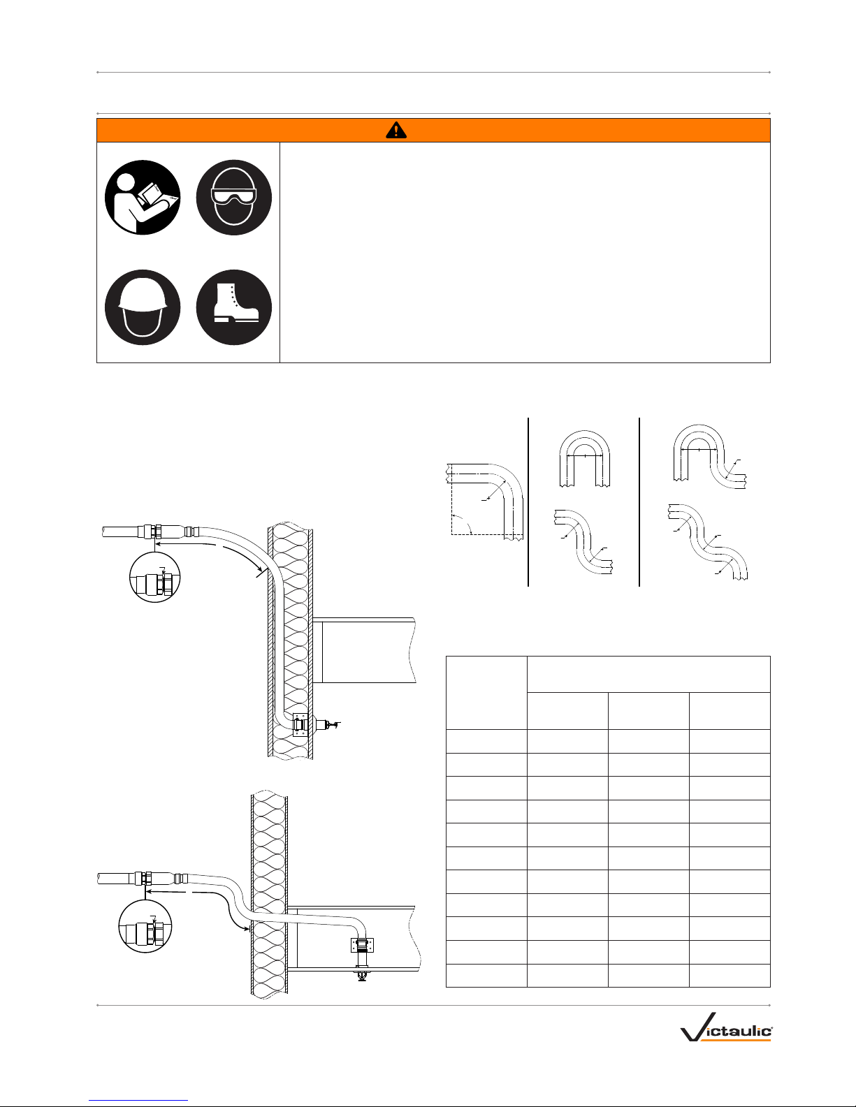
Flexible Hose Bend Characteristics:
NOTE: For out-of-plane (three-dimensional) bends, care shall be taken
to avoid imparting torque on the flexible hose.
90°
OR
OR
Minimum
Bend Radius
Minimum
Bend Radius
Minimum
Bend Radius
Minimum
Bend Radius
Minimum
Bend Radius
Minimum
Bend Radius
Minimum
Bend Radius
2X
Minimum
Bend
Radius
2X
Minimum
Bend
Radius
WARNING
• Read and understand all instructions before attempting to install any Victaulic® VicFlex™ products.
• Wear safety glasses, hardhat, and foot protection.
• These installation instructions are intended for an experienced, trained installer.
• The installer shall understand the use of this product and why it was specified for the particular
application.
• The installer shall understand common industry safety standards and potential consequences of
improper product installation.
• It is the system designer’s responsibility to verify suitability of stainless steel flexible hose for use
with the intended fluid media within the piping system and external environment.
• The material specifier shall evaluate the effect of chemical composition, pH level, operating
temperature, chloride level, oxygen level, and flow rate on stainless steel components to confirm
system life will be acceptable for the intended service.
Failure to follow these instructions could cause improper sprinkler operation and product failure,
resulting in death or serious personal injury and property damage.
The following table is used when the ambient temperature is maintained
between 40° F/4° C and 60°F/16°C around the wet piping system.
Ambient
Temperature
Exposed to
Discharge End
of Sprinkler
°F/°C
Exposed Minimum Barrel Length “Y” inches/mm
40°F
4°C
50°F
10°C
60°F
16°C
40 0 0 0
4 0 0 0
30 0 0 0
-1 0 0 0
20 4 0 0
-7 100 0 0
10 8 1 0
-12 200 25 0
0 12 3 0
-18 300 75 0
-10 14 4 1
-23 350 100 25
-20 14 6 3
-29 350 150 75
-30 16 8 4
-34 400 200 100
-40 18 8 4
-40 450 200 100
-50 20 10 6
-46 500 250 150
-60 20 10 6
-51 500 250 150
NOTE: Expo sed minimum bar rel lengths are inclusive u p to 30-mph/48-kp h wind velocit ies
SIDEWALL
Y
Exterior
Heated
Space
Unheated
Space
Face of
Fitting
PENDENT
Y
Exterior
Face of
Fitting
Heated
Space
Unheated
Space
Maximum Working Pressure
Rating:
175 psi/12 Bar/1207 kPa
Connection to Branch Line
(Inlet):
1 inch/25 mm NPT or BSPT
Minimum Bend Radius:
2 inch/50 mm (UL)
7 inch/178 mm (FM)
K-Factor of Sprinkler:
5.6 US/80 metric
Maximum Number of 90° Bends:
4 Bends (UL) – All Hose Lengths
2 Bends (FM) – 38-inch/965-mm
Hose Length
3 Bends (FM) – 50-inch/1270-mm
Hose Length
4 Bends (FM) – 58-inch/1475-mm
Hose Length
Page 2
I-VICFLEX.VS1_2
REV_D
I-VICFLEX.VS1 / Victaulic® VicFlex™ Style VS1 Dry Sprinkler / Installation Instructions
IMPORTANT INSTALLATION INFORMATION
• Victaulic® VicFlex™ Style VS1 Dry Sprinklers shall be installed
according to current, applicable National Fire Protection
Association (NFPA 13, 13D, 13R, etc.) standards or equivalent
standards. Style VS1 Dry Sprinklers are intended to be installed
in wet, dry, or preaction actuated systems. Deviations from these
standards or alterations to Style VS1 Dry Sprinklers will void any
Victaulic warranty and will impact system integrity. Installations
shall meet the provisions of the local authorit y having jurisdiction
and local codes, as applicable.
• Victaulic® VicFlex™ Sprinkler Fittings shall not be intermixed with
other manufacturer’s flexible sprinkler products.
• Transport and store Style VS1 Dry Sprinklers in a cool, dry
environment in their original packaging.
• Refer to the specific Victaulic product submittal for applications
and listing information. Submittals can be downloaded at
victaulic.com.
• Size the piping system to provide the minimum operating pressure
of 7 psi/0.5 Bar/48 kPa.
• Per NFPA requirements, flush the system to remove foreign
material. Continue to flush the system until water runs clear.
• DO NOT install sprinkler system piping through heating ducts.
• DO NOT connect sprinkler system piping to domestic hot water
systems.
• DO NOT install Style VS1 Dry Sprinklers where they will be
exposed to temperatures that exceed the maximum ambient
temperature rating for the sprinkler and sprinkler fittings.
• Style VS1 Dry Sprinklers have limited flexibility* and are
intended only to be installed with bends not less than their
respective minimum bend radii. DO NOT install flexible hose in
a straight configuration.
• Protect wet piping systems from freezing temperatures.
• If construction is altered, the building owner or their representative
is responsible for referencing applicable standards to determine if
additional Style VS1 Dry Sprinklers or other system adjustments
are required.
• DO NOT install Style VS1 Dry Sprinklers that have been dropped
or struck by another object, even if they do not appear damaged.
Never install glass bulb sprinklers if the bulb is cracked or if there
is a loss of liquid from the bulb. Discard and replace any Style VS1
Dry Sprinklers that are damaged or show signs of corrosion.
• Before installation, verify that the St yle VS1 Dry Sprinkler is the
proper style, orifice size, and temperature rating for the intended
service.
• VICTAULIC® VICFLEX™ STYLE VB2 BRACKET ASSEMBLIES
SHALL BE USED ONLY WITH STYLE VS1 RECESSED PENDENT
SPRINKLERS.
• VICTAULIC® VICFLEX™ STYLE VB3 BRACKET ASSEMBLIES
SHALL BE USED ONLY WITH STYLE VS1 CONCEALED
PENDENT SPRINKLERS.
• DO NOT paint, coat, plate, or alter Style VS1 Dry Sprinklers. Style
VS1 Dry Sprinklers that have been altered from their manufactured
condition may not function properly and will void any agency
listings and/or approvals.
• DO NOT test Style VS1 Dry Sprinklers with a heat source. The
glass bulb can weaken or shatter if exposed to a heat source
during testing.
• Style VS1 Dry Sprinklers that have operated cannot be
reassembled or reused, per NFPA requirements. When replacing
sprinklers, use new sprinklers of the same type, orifice,
temperature, and response.
• DO NOT clean St yle VS1 Dry Sprinklers with soapy water,
detergents, ammonia, cleaning fluids, or other chemicals. Remove
any dust, lint, etc. with a soft, dry cloth.
• Inspect Style VS1 Dry Sprinklers on a regular basis for corrosion,
mechanical damage, obstructions, etc. The frequency of
inspections may vary due to corrosive atmospheres/water supplies
and activities around the sprinklers.
• DO NOT hang anything from or at tach anything to Style VS1 Dry
Sprinklers. Obstructing the discharge pattern will prevent the
sprinkler from operating properly.
• The owner is responsible for maintaining the fire protection system
in proper operating condition.
• For minimum maintenance and inspection requirements, refer to
NFPA 25 and any other applicable NFPA standards that describe
the care and maintenance of sprinkler systems. In addition, the
authority having jurisdiction may have additional maintenance,
testing, and inspection requirements that shall be followed.
WARNING
• Replacement/relocation of this Victaulic® VicFlex™ Style VS1
Dry Sprinkler SHALL be performed by qualified personnel
familiar with the system’s original design criteria, sprinkler
listings/ approvals, and state and local codes (including NFPA 13
standards).
Failure to replace/relocate a Style VS1 Dry Sprinkler properly could
affect its performance during a fire, resulting in serious personal
injury and property damage.
* Reference UL 2443: Section 25.1
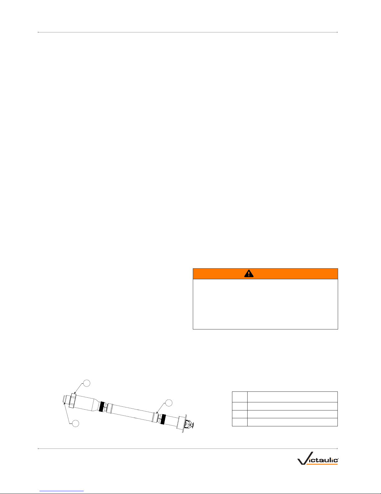
STYLE VS1 SPRINKLER ASSEMBLY DRAWING
3
2
1
Recessed Pendent Shown Above
Item Description
1 Swivel Hex Nut
2 Weld Fitting
3 Inlet
Page 3
I-VICFLEX.VS1_3
REV_D
I-VICFLEX.VS1 / Victaulic® VicFlex™ Style VS1 Dry Sprinkler / Installation Instructions
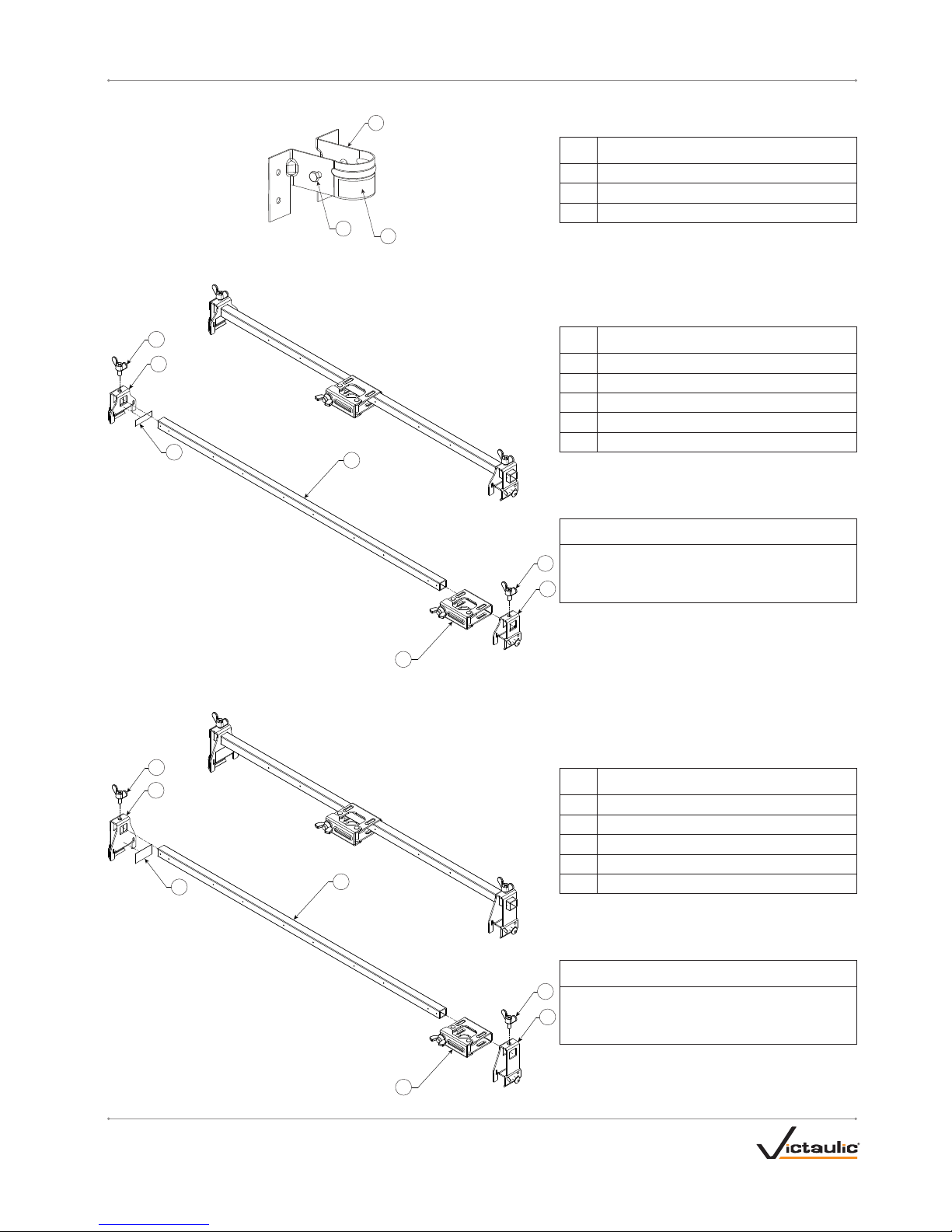
STYLE VB1 BRACKET ASSEMBLY DRAWING
2
1
3
STYLE VB2 BRACKET ASSEMBLY DRAWING
2
3
1
4
5
3
5
STYLE VB3 BRACKET ASSEMBLY DRAWING
2
3
1
4
5
3
5
Item Description
1 Style VB1 Bracket
2 Hex Cap Screw
3 Relocation Warning Label
Item Description
1 24-inch/610-mm or 48-inch/1219-mm Square Bar*
2 Center Gate Assembly with Wing Nut
3 Style VB2 End Bracket with Tapping Screw
4 Relocation Warning Label
5 Wing Screw
* Reference submittal document 10.91 for listing
information. Square bar length is in reference to nominal
ceiling grid spacing.
NOTICE
• VICTAULIC® VICFLEX™ STYLE VB2 BRACKET
ASSEMBLIES SHALL BE USED ONLY WITH
STYLE VS1 RECESSED PENDENT SPRINKLERS.
Item Description
1 24-inch/610-mm or 48-inch/1219-mm Square Bar*
2 Center Gate Assembly with Wing Nut
3 Style VB3 End Bracket with Tapping Screw
4 Relocation Warning Label
5 Wing Screw
* Reference submittal document 10.91 for listing
information. Square bar length is in reference to nominal
ceiling grid spacing.
NOTICE
• VICTAULIC® VICFLEX™ STYLE VB3 BRACKET
ASSEMBLIES SHALL BE USED ONLY WITH
STYLE VS1 CONCEALED PENDENT SPRINKLERS.
Page 4

I-VICFLEX.VS1_4
REV_D
I-VICFLEX.VS1 / Victaulic® VicFlex™ Style VS1 Dry Sprinkler / Installation Instructions
STYLE VS1 SPRINKLER ASSEMBLY PITCHING REQUIREMENTS
SIDEWALL
Continuous Downward Slope
ACCEPTABLE PITCH
Inlet
Outlet
Heated Space
Unheated Space
Inlet
Outlet
Low Point
UNACCEPTABLE PITCH
Unheated Space
Heated Space
PENDENT
Continuous Downward Slope
ACCEPTABLE
Inlet
Outlet
Heated Space
Unheated Space
Outlet
Low Point
UNACCEPTABLE
Unheated Space
Inlet
Heated Space
Page 5

I-VICFLEX.VS1_5
REV_D
I-VICFLEX.VS1 / Victaulic® VicFlex™ Style VS1 Dry Sprinkler / Installation Instructions
FOR DRY SYSTEMS ONLY:
• The Style VS1 Dry Sprinkler’s inlet shall be installed only into the outlet of a fitting (excluding elbows) or welded outlet that meets the dimensional
requirements of ANSI B16.3 and ANSI B16.4, Class 125 and Class 150. Use a sample fitting to confirm proper engagement and to verify that
there is no interference between the sprinkler and the fitting.
Style VS1 Dry Sprinklers in an unheated space shall be installed with a continuous downward slope along its entire length from the
branch line fitting to the sprinkler. No localized low points shall be present along the length of the Style VS1 Dry Sprinkler.
Style VS1 Dry Sprinklers in an unheated space are not permitted to be installed into the top of the branch line piping. Style VS1 Dry
Sprinklers shall be installed into the side or from the bottom of the branch line piping.
In a heated space, if a portion of the Style VS1 Dry Sprinkler is installed from the top of a branch line and then extends into an
unheated space, it shall be installed with a continuous downward slope along the entire length from the inside wall to the outlet of
the sprinkler. No localized low points shall be present along the length of the sprinkler in the unheated space. Refer to the drawing
below.
Heated Space
Unheated Space
Inlet
Outlet
Downward
Slope
FOR WET SYSTEMS ONLY:
• DO NOT install Style VS1 Dry Sprinklers into any threaded elbow, thread-by-thread coupling, or fitting that interferes with thread penetration.
The inlet of the Style VS1 Dry Sprinkler SHALL NOT bottom out in the fitting. Use a sample fit ting to confirm proper engagement.
• To ensure unobstructed flow during operation, the Style VS1 Dry Sprinkler shall be installed into a fitting that will prevent water and debris from
accumulating at the dry sprinkler’s inlet.
• Verify that the exposed minimum barrel length in the heated space is measured and maintained in accordance with the table on page 1.
In a heated space, if a portion of the Style VS1 Dry Sprinkler extends into an unheated space, it shall be installed with a continuous
downward slope along the entire length from the inside wall to the outlet end of the dry sprinkler. No localized low points shall be
present along the length of the sprinkler in the unheated space. Refer to the drawing above.
Page 6

I-VICFLEX.VS1_6
REV_D
I-VICFLEX.VS1 / Victaulic® VicFlex™ Style VS1 Dry Sprinkler / Installation Instructions
STYLE VB1 BRACKET INSTALLATION FOR
WOOD OR METAL JOISTS/STUDS
WARNING
• DO NOT attempt to adjust or remove a Style VS1 Dry Sprinkler
while the sprinkler system is pressurized.
Failure to follow this instruction could result in death or serious
personal injury and property damage.
1. Cut a hole in the finished ceiling or wall. Refer to the table below
for hole sizes.
Minimum and Maximum Hole Sizes
Sprinkler Style
Hole Sizes – inches/millimeters
Minimum Maximum
VS1 Recessed
2 2 ⁄
51 60
VS1 Concealed
2 ⁄ 2 ¾
67 70
VS1 Sleeve/Skirt
1 ¾ 2 ½
44 64
Engage Wrench
Only On Swivel
Hex Nut
2. Apply a non-hardening
pipe-joint compound or
two to three wraps of PTFE
thread sealant tape to the
male threads of the Style
VS1 Dry Sprinkler’s inlet, in
accordance with the pipe
joint compound or tape
manufacturer’s instructions.
2a. Using a 2-inch wrench,
tighten the swivel hex
nut at the Style VS1
Dry Sprinkler’s inlet to a
torque of 30 ft-lbs/41 N•m
(approximately ½ to ¾ of a
turn past hand-tight).
Remove Hex Cap
Screw for Installation
3. Using a ⁄-inch hex socket,
remove the hex cap screw
from the bracket.
4. Snap the bracket onto the
weld fitting, as shown to the
left. Verify that the slot of the
bracket aligns with the lip on
the weld fitting.
• An alternative to step 4 is
to snap the bracket onto the
outlet tube, as shown.
5. Place the bracket assembly
in the desired position on
the wood or metal joist/
stud. Verify that the sprinkler
is oriented in the proper
position.
5a. Using a ⁄-inch hex socket,
re-install the hex cap screw.
Tighten the hex cap screw
to 15 inch-lbs/1.7 N•m
(approximately one to two
turns past hand-tight). This
will retain the sprinkler
orientation in relation to the
bracket mounting flanges.
6. Anchor the bracket in the desired location on the wood or metal
joist/stud by using two #10 x 1 ½-inch long wood screws (for wood
joists/studs shown above) or two #10 x 1 ½-inch long sheet metal
screws (for metal joists/studs). NOTE: Victaulic does not supply
wood screws or sheet metal screws.
NOTICE
• Always reference pages 4 and 5 of this instruction sheet for
Style VS1 Sprinkler Assembly pitching requirements.
Page 7

I-VICFLEX.VS1_7
REV_D
I-VICFLEX.VS1 / Victaulic® VicFlex™ Style VS1 Dry Sprinkler / Installation Instructions
STYLE VB2 AND STYLE VB3 BRACKETS –
INSTALLATION FOR ASTM C635 CEILING
SUSPENSION SYSTEMS INSTALLED WITH
LAY-IN TILES (IN ACCORDANCE WITH
ASTM C636 STANDARDS)
WARNING
• DO NOT attempt to adjust or remove a Style VS1 Dry Sprinkler
while the sprinkler system is pressurized.
Failure to follow this instruction could result in death or serious
personal injury and property damage.
Engage Wrench
Only On Swivel
Hex Nut
1. Apply a non-hardening
pipe-joint compound or
two to three wraps of PTFE
thread sealant tape to the
male threads of the Style
VS1 Dry Sprinkler’s inlet, in
accordance with the pipe
joint compound or tape
manufacturer’s instructions.
1a. Using a 2-inch wrench,
tighten the swivel hex
nut at the Style VS1
Dry Sprinkler’s inlet to a
torque of 30 ft-lbs/41 N•m
(approximately ½ to ¾ of a
turn past hand-tight).
For adjustment purposes, the wing screw on top of each end bracket
assembly can be loosened to allow the end bracket to slide on the
square bar. Tighten the wing screw on top of each end bracket
assembly to a torque of 36 inch-lbs/4 N•m (approximately ½ to ¾ of a
turn past hand-tight) to secure the end bracket to the square bar.
2. Attach the end brackets of the Style VB2 Bracket to the T-bar
rails of an ASTM C635 ceiling suspension system installed in
accordance with ASTM C636 standards. Verify that the ends of the
Style VB2 Bracket engage the rails.
Side Facing the
Opening of the
Center Gate
Assembly
2a. For center-of-tile installations, align the end bracket with the
center-of-tile slot of the T-bar rail (with the side facing the opening
of the center gate assembly), as shown above.
2b. Apply light downward pressure, as shown above, to maintain the
position of the end bracket flat against the T-bar rail. To secure
the end brackets to the T-bar rails, tighten the pre-installed sheet
metal screws using a #2 recessed square drive bit. Penetrate
through the T-bar rail until the end bracket is seated fully against
the T-bar rail. DO NOT over-tighten the screws. Over-tightening
will cause the screw to strip, resulting in an unsecured bracket
connection.
3. Move the center gate assembly of the Style VB2 Bracket to the
desired location. Loosen the wing nut to open the center gate
assembly, then slide the sprinkler reducing nipple into the center
gate assembly. NOTE: The pivot screw of the center gate assembly
is staked to resist removal of the wing nut.
Page 8

I-VICFLEX.VS1INSTALLATION INSTRUCTIONS
Victaulic® VicFlex™ Style VS1 Dry Sprinkler
For complete contact information, visit victaulic.com
I-VICFLEX.VS1 8919 REV D UPDATED 07/2018 Z000VS1000
VICTAULIC AND VICFLEX ARE REGISTERED TRADEMARKS OR TRADEMARKS OF VICTAULIC COMPANY AND/OR ITS AFFILIATED ENTITIES
IN THE UNITED STATES AND/OR OTHER COUNTRIES. © 2018 VICTAULIC COMPANY. ALL RIGHTS RESERVED.
For center-of tile installations, position the center gate assembly
between the two reference marks on the square bar, as shown above.
3a. Close the center gate assembly around the sprinkler reducing
nipple. Swing the pivot screw and washer into the slot on the
gate, and tighten the wing nut to a torque of 50 inch-lbs/6 N•m
(approximately hand-tight, plus ½ to ¾ of a turn). NOTE: Verify
that the washer is seated under the head of the wing nut.
 Loading...