

Victaulic Vic-300 MasterSeal 761 Series, Vic-300 MasterSeal 461 Series Installation And Maintenance Instructions Manual
Page 1
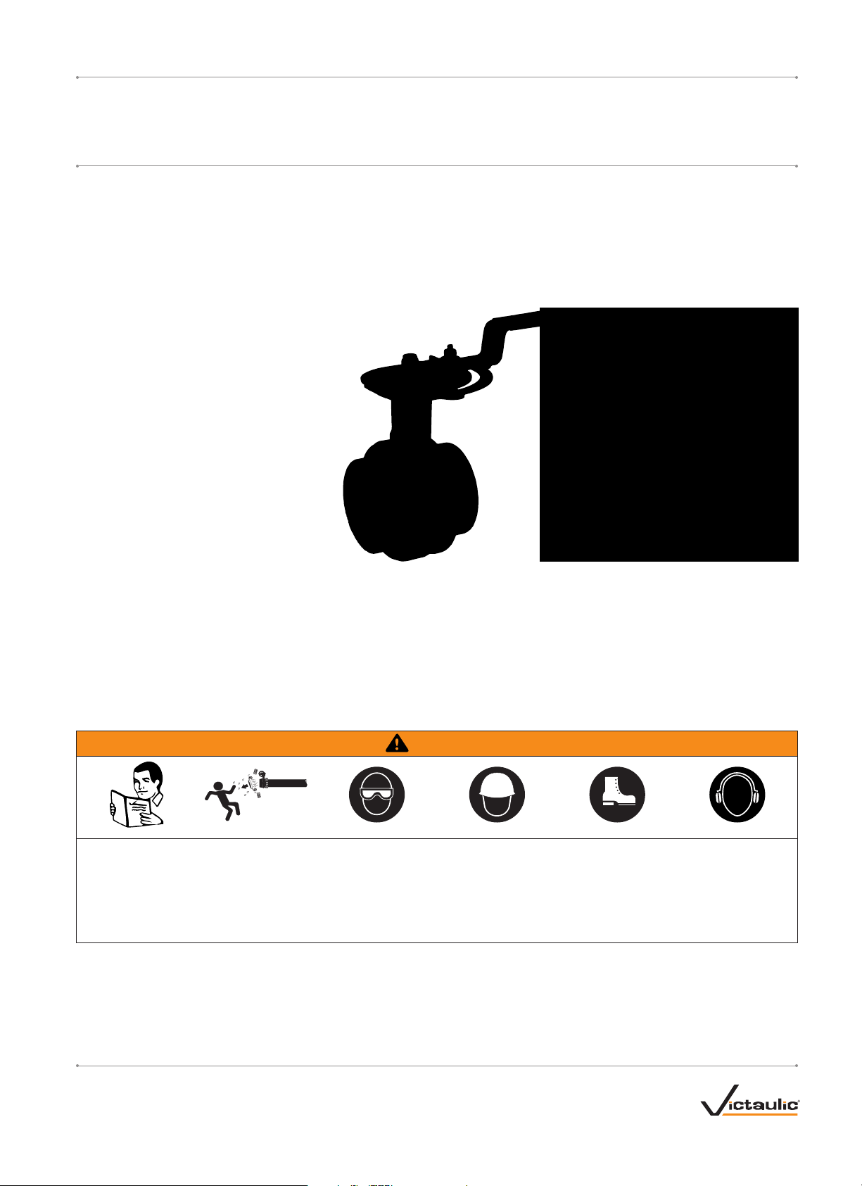
Series 761 Vic-300® MasterSeal™ Carbon Steel Butterfly Valve
Series 461 Vic-300
®
MasterSeal™ Stainless Steel Butterfly Valve
I-VIC300MSINSTALLATION AND MAINTENANCE INSTRUCTIONS
SERI ES 7 61 SERI ES 4 61
WARNING
• Read and understand all instructions before attempting to install, remove, adjust, or maintain any Victaulic piping products.
• Depressurize and drain the piping system before attempting to install, remove, adjust, or maintain any Victaulic piping products.
• Wear safety glasses, hardhat, foot protection, and hearing protection.
Failure to follow instructions and warnings could cause system failure, resulting in death or serious personal injury and property damage.
victaulic.com
VICTAULIC IS A REGISTERED TRADEMARK OF VICTAULIC COMPANY. © 2014 VICTAULIC COMPANY. ALL RIGHTS RESERVED.
REV_F
I-VIC300MS
Page 2
I-VIC300MS / Vic-300® MasterSeal™ Butterfly Valves / Installation and Maintenance Instructions
TABLE OF CONTENTS
Hazard Identification ......................................1
Butterfly Valve Components.................................2
Installation Information.....................................3
Vic-Flange® Adapter Notes .................................3
System-Related Considerations ..............................3
Prevention of Stainless Steel Product Contamination ..............3
Stem Seal Replacement for 2 - 12-inch/60.3 - 323.9-mm Valves .....4
Setting the Memory Stop Feature on 2 - 6-inch/60.3 - 168.3-mm
Valves with 10-Position Handles ...........................6
Using the Infinitely Variable Feature on 2 - 6-inch/60.3 - 168.3-mm
Valves with 10-Position Handles ...........................6
Memory Stop Feature on 8-inch/219.1-mm Valves with
Lever Lock Handles .....................................7
“A” - Setting the Memory Stop Feature on 8-inch/219.1-mm
Valves with Lever Lock Handles ............................7
“B” - Setting the Memory Stop Feature on 8-inch/219.1-mm
Valves with Lever Lock Handles ............................9
10-Position Handle Removal for 2 - 6-inch/60.3 - 168.3-mm
Valves ..............................................10
Lever Lock Handle Removal for 8-inch/219.1-mm Valves..........12
Tamper-Resistant Handle Kit Installation for 2 - 6 -inch/
60.3 - 168.3-mm Valves with 10-Position Handles ............14
Tamper-Resistant Handle Kit Installation for 8-inch/219.1-mm
Valves with Lever Lock Handles ...........................17
Telescopic Handle Kit Installation for 10 - 12-inch/
273.0 - 323.9-mm Series 761 Valves.......................19
Gear Operator Installation for 2 - 12-inch/
60.3 - 323.9-mm Valves ................................22
Adjusting and Setting the Closed Travel Limit Stops
of the Gear Operator
Adjusting and Setting the Open Travel Limit Stops
of the Gear Operator
Memory Stop Kit Installation for 2 - 12-inch/60.3 - 323.9-mm
Gear-Operated Valves ..................................25
Thermal Barrier Kit Installation for 2 - 12-inch/
60.3 - 323.9-mm Valves ................................27
Insulation Extension Kit for 2 - 8-inch/60.3 - 219.1-mm
Gear-Operated Valves ..................................28
Insulation Extension Kit Installation for 2 - 8-inch/60.3 - 219.1-mm
Gear-Operated Valves ..................................29
Insulation Extension Kit for 2 - 6-inch/6 0.3 - 168.3-mm
Valves with 10-Position Handles ..........................30
Insulation Extension Kit Installation for 2 - 6-inch/60.3 - 168.3-mm
Valves with 10-Position Handles .......................... 31
Insulation Extension Kit for 8-inch/219.1-mm Valves
with Lever Lock Handles ................................32
Insulation Extension Kit Installation for 8-inch/219.1-mm Valves
with Lever Lock Handles ................................33
...................................24
...................................24
HAZARD IDENTIFICATION
Definitions for identifying the various hazard levels are
provided below. When you see this symbol, be alert to the
possibility of personal injury. Carefully read and fully
u nderstand the message that follows.
DANGER
• The use of the word “DANGER” identifies an immediate
hazard with a likelihood of death or serious personal injury
if instructions, including recommended precautions, are not
followed.
WARNING
• The use of the word “WARNING” identifies the presence
of hazards or unsafe practices that could result in death or
serious personal injury if instructions, including recommended
precautions, are not followed.
CAUTION
• The use of the word “CAUTION” identifies possible hazards or
unsafe practices that could result in personal injury and product
or property damage if instructions, including recommended
precautions, are not followed.
NOTICE
• The use of the word “NOTICE” identifies special instructions
that are important but not related to hazards.
victaulic.com
VICTAULIC IS A REGISTERED TRADEMARK OF VICTAULIC COMPANY. © 2014 VICTAULIC COMPANY. ALL RIGHTS RESERVED.
REV_F
I-VIC300MS_1
Page 3
I-VIC300MS / Vic-300® MasterSeal™ Butterfly Valves / Installation and Maintenance Instructions
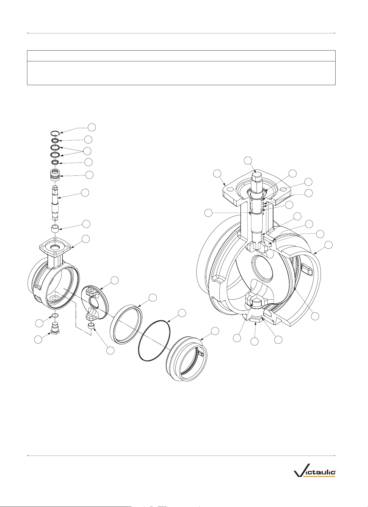
BUTTERFLY VALVE COMPONENTS
NOTICE
• Drawings and/or pictures in this manual may be exaggerated for clarity.
• The product, along with these installation and maintenance instructions, contains trademarks, copyrights, and/or patented features that are
the exclusive property of Victaulic.
Bill of Materials
Item Qty. Description Item Qty. Description
1 1 Valve Body Mounting Flange 8 1 Upper Bearing
2 1 End Face 9 1 Lower Bearing
12
13
14
13
3 1 Disc 10 1 O-Ring
4 1 Seat 11 1 Seal Cartridge
5 1 O-Ring 12 1 Retaining Ring
6 1 Stem 13 2 O-Ring
7 1 Stem Nut 14 2 O-Ring
6
10
7
11
1
12
13
6
14
13
11
8
8
5
4
1
2
3
4
5
3
2
8
7
10
9
victaulic.com
VICTAULIC IS A REGISTERED TRADEMARK OF VICTAULIC COMPANY. © 2014 VICTAULIC COMPANY. ALL RIGHTS RESERVED.
I-VIC300MS_2
REV_F
Page 4
I-VIC300MS / Vic-300® MasterSeal™ Butterfly Valves / Installation and Maintenance Instructions
INSTALLATION INFORMATION
Series 761 and 461 Butterfly Valves are designed with grooved ends
for use with Victaulic grooved pipe couplings. Refer to the instructions,
supplied with the Victaulic coupling or Vic-Flange® Adapter, and the
notes in this section for installing Series 761 or 461 Butterfly Valves into
the piping system.
DO NOT INSTALL SERIES 761 OR 461 BUTTERFLY VALVES INTO
THE SYSTEM WITH THE DISC IN THE FULLY-OPEN POSITION.
• When using Series 761 or 461 Butterfly Valves for throttling
service, Victaulic recommends positioning the disc no less than
30 degrees open. For best results, the disc should be between
30 and 70 degrees open. High pipeline velocities and/or throttling
with the disc less than 30 degrees open may result in noise,
vibration, cavitation, severe line erosion, and/or loss of control.
For details regarding throttling services, contact Victaulic.
• Victaulic recommends limiting the flow velocities for water service
to 20 feet/second (6 meters/second). When higher flow velocities
are necessary, contact Victaulic. When dealing with flow media
other than water, contact Victaulic.
• Lubricated nitrile “T” seat seals are recommended for dry or
lubricated gas services.
• When directly connecting an end cap to a Series 761 or 461
Butterfly Valve, use only an end cap with a tapped hole for
attaching a pressure relief device. If the valve is opened then
closed unknowingly while the end cap is attached, the space
between the disc and end cap will be filled and pressurized. A
sudden release of energy can occur if the end cap is removed
while the space behind it is pressurized. PRESSURE MUST
BE VENTED THROUGH THE TAP BEFORE ATTEMPTING TO
REMOVE THE CAP.
DANGER
• When directly connecting an end cap to a
butterfly valve, use only an end cap with
a tapped hole for attaching a pressure
relief device.
• Pressure must be vented through the tap
before attempting to remove the cap.
Failure to follow these instructions could
result in death or serious personal injury.
VIC-FLANGE® ADAPTER NOTES
• Style 741 Vic-Flange® Adapters can be used on all sizes of Series
761 Butterfly Valves.
• Series 761 Butterfly Valves cannot be connected directly to flanged
components with Style 743 Vic-Flange® Adapters. A No. 46 ANSI
300 groove-by-flange adapter is required for this application.
• Style 441 Stainless Steel Vic-Flange® Adapters can be used on all
sizes of Series 461 Butterfly Valves.
SYSTEM-RELATED CONSIDERATIONS
• Series 761 and 461 Butterfly Valves and connecting piping must
be supported properly to prevent the joints from being subjected to
bending loads, shear loads, or any other external loads.
• The maximum allowable corrosion allowance is 0.8inch/2 mm.
• Welding to Series 761 and 461 Butterfly Valves and couplings is
not permitted.
PREVENTION OF STAINLESS STEEL PRODUCT
CONTAMINATION
These recommendations are provided as a general guideline to help
prevent surface contamination of stainless steel products.
Handling and Storage
1. Stainless steel products should be handled only with non-
contaminating apparatus (i.e. nylon straps or apparatus protected
with a non-contaminating buffer material).
2. If carbon steel straps are used, a buffer material must be placed
between the strap and the stainless steel product. Common noncontaminating buffer materials include wood, cardboard, paper,
canvas, and other stainless steel material.
3. Stainless steel products must be stocked on non-contaminating
racks or skids.
4. Stainless steel products must be stocked in an area separate from
iron or carbon steel products.
5. Do no climb on or stand on stainless steel products.
6. In storage areas where salt is present in the air, stainless steel
products must be covered with a plastic tarp.
Shipping
1. Stainless steel products must be shipped with new, non-
contaminating and non-damaging packing materials.
2. If markings are required directly on stainless steel products, the
marking must have a water-soluble chloride content less than 50
parts per million (ppm). The chloride content must be measured
upon drying of the marking.
3. Identification tags and connectors, if required, must be
constructed from non-contaminating materials.
4. Stainless steel products must be shipped separately from iron
or carbon steel products. If stainless steel and/or iron or carbon
steel products must be shipped together, care must be taken
to separate the dissimilar materials completely by using a noncontaminating buffer.
WARNING
• The system designer is responsible for verifying suitability of
stainless steel materials with the intended fluid media.
• The effect of chemical composition, pH level, operating
temperature, chloride level, oxygen level, and flow rate on
stainless steel materials must be evaluated to confirm system
life will be acceptable for the intended service.
Failure to follow these instructions could cause product failure,
resulting in serious personal injury and property damage.
victaulic.com
VICTAULIC IS A REGISTERED TRADEMARK OF VICTAULIC COMPANY. © 2014 VICTAULIC COMPANY. ALL RIGHTS RESERVED.
REV_F
I-VIC300MS_3
Page 5
I-VIC300MS / Vic-300® MasterSeal™ Butterfly Valves / Installation and Maintenance Instructions
STEM SEAL REPLACEMENT FOR
2 – 12-INCH/60.3 – 323.9-MM VALVES
WARNING
• Read and understand all instructions before
attempting to replace the stem seals.
Failure to follow all instructions could result in
serious personal injury and/or property damage.
WARNING
• THE PUMP MUST BE SHUT OFF to
prevent flow from passing through the
valve during the following procedures.
Failure to follow this instruction could cause product failure,
resulting in serious personal injury and/or property damage.
4. Using retaining-ring pliers or a similar device, remove the retaining
ring from around the stem assembly, as shown above. If the
retaining ring is bent from its original shape, replace it with a new,
Victaulic-supplied retaining ring.
NOTICE
• THE STEM SEAL REPLACEMENT PROCEDURE SHOULD BE
COMPLETED ONLY IF LEAKAGE IS OCCURRING FROM THE
STEM.
• Make sure the correct stem seal kit was ordered by verifying the
o-ring material.
• O-rings for all valve sizes (12 total) are included with the kit.
However, only four o-rings are required to repair one valve.
Make sure the correct size o-rings are used for the stem seal
replacement procedure. Discard any unused o-rings.
1. Removal of the handle assembly or gear operator can be
performed without removing the valve from the piping system. THE
PUMP MUST BE SHUT OFF to prevent flow from passing through
the valve during removal of the handle assembly or gear operator.
2. To remove the handle assembly: Refer to the appropriate handle
removal section in this manual.
3. To remove the gear operator: Note the current orientation of the
gear operator before proceeding with the following steps. AS A
REFERENCE FOR GEAR OPERATOR RE-INSTALLATION: Place a
mark on the gear operator, the stem, and the valve body mounting
flange with a permanent marker or paint pen.
3a. Place the valve disc in the OPEN position by turning the
handwheel of the gear operator until the pointer is pointing toward
the OPEN position.
3b. Remove the four existing hex-head screws and lock washers
that attach the gear operator to the valve body mounting flange.
NOTE: These hex-head screws and lock washers are required for
re-installation.
3c. Pull straight upward to remove the gear operator and existing drive
bushing from the valve body mounting flange. These items are
required for re-installation. DO NOT REMOVE OR ROTATE THE
STEM.
3d. Remove any debris from the valve body mounting flange.
5. Remove the stem assembly from the disc/valve body. Be careful
not to damage the flats of the drive hub during removal.
6. Remove the seal cartridge from the stem.
victaulic.com
VICTAULIC IS A REGISTERED TRADEMARK OF VICTAULIC COMPANY. © 2014 VICTAULIC COMPANY. ALL RIGHTS RESERVED.
I-VIC300MS_4
REV_F
Page 6
I-VIC300MS / Vic-300® MasterSeal™ Butterfly Valves / Installation and Maintenance Instructions
11. Install two new o-rings onto the seal cartridge, as shown above.
7. Using an o-ring pick or a similar device, remove the two internal
and two external o-rings from the seal cartridge.
8. Clean the stem and the interior and exterior surfaces of the seal
cartridge. Check the surfaces of the stem and seal cartridge for
burrs and sharp edges. File any burrs and sharp edges to prevent
o-rings from being cut during re-assembly.
9. Lubricate the seal cartridge and o-rings with Vic-Lube™ or another
compatible material, such as silicone.
CAUTION
• Use a compatible lubricant to prevent the o-rings from pinching/
tearing during installation.
Failure to follow this instruction could result in valve leakage
through the stem.
12. Insert the stem into the seal cartridge.
13. Insert the stem assembly into the valve body/disc. Make sure the
rectangular end of the disc aligns with the stem. NOTE: The seal
cartridge must seat fully in the valve body.
14. Using retaining-ring pliers or a similar device, install the retaining
ring over the stem assembly. Make sure the retaining ring fully
seats in the recess in the valve body.
15. Re-install the handle assembly or gear operator onto the valve.
10. Install two new o-rings into the seal cartridge, as shown above.
victaulic.com
VICTAULIC IS A REGISTERED TRADEMARK OF VICTAULIC COMPANY. © 2014 VICTAULIC COMPANY. ALL RIGHTS RESERVED.
REV_F
16. Operate the valve through a full-open and full-closed cycle to verify
proper operation, then place the system back into service.
I-VIC300MS_5
Page 7

I-VIC300MS / Vic-300® MasterSeal™ Butterfly Valves / Installation and Maintenance Instructions
SETTING THE MEMORY STOP FEATURE ON
2 – 6-INCH/60.3 – 168.3-MM VALVES WITH
10-POSITION HANDLES
1. Using the handle, place the valve disc in the desired “open”
position.
2. Loosen the memory stop nut, as shown above.
USING THE INFINITELY VARIABLE FEATURE ON
2 – 6-INCH/60.3 – 168.3-MM VALVES WITH
10-POSITION HANDLES
1. Remove the detent screw.
2. Remove the hex nut, lock washer, flat washer, and bolt from the
plate, as shown above.
3. Move the memory stop hardware to make contact with the side of
the 10-Position Handle, as shown above. Re-tighten the memory
stop nut to maintain the desired “open” location.
3. Install the hardware, removed in step 2, into the center hole in the
handle, as shown above.
4. To use the memory stop feature with the infinitely variable handle
option, refer to the instructions on the following page for setting the
memory stop.
victaulic.com
VICTAULIC IS A REGISTERED TRADEMARK OF VICTAULIC COMPANY. © 2014 VICTAULIC COMPANY. ALL RIGHTS RESERVED.
I-VIC300MS_6
REV_F
Page 8
I-VIC300MS / Vic-300® MasterSeal™ Butterfly Valves / Installation and Maintenance Instructions
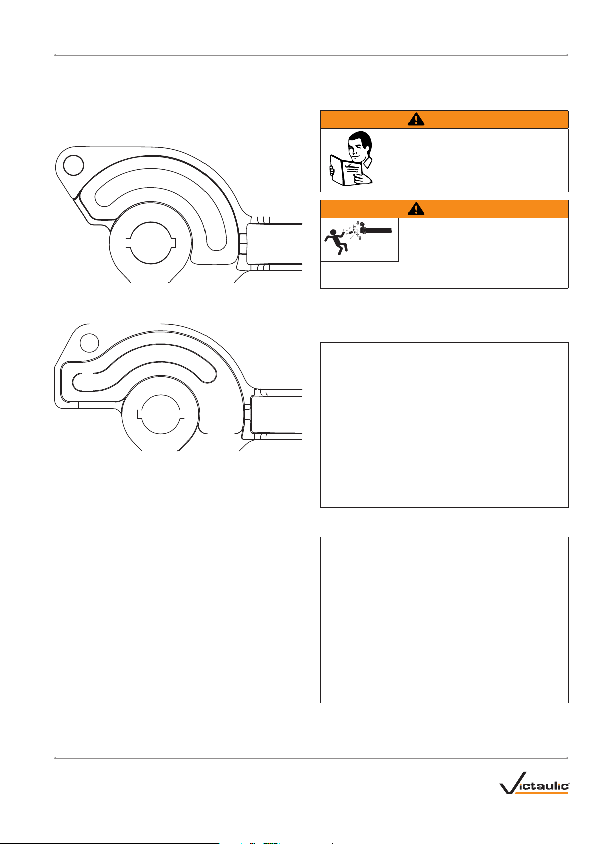
MEMORY STOP FEATURE ON 8-INCH/219.1-MM
VALVES WITH LEVER LOCK HANDLES
Determine the Lever Lock Handle design that is installed currently on
the valve.
If the Lever Lock Handle looks like the graphic below, follow the
instructions designated as “A” on this page.
If the Lever Lock Handle looks like the graphic below, follow the
instructions designated as “B” on page 9.
“A” – SETTING THE MEMORY STOP FEATURE
ON 8-INCH/219.1-MM VALVES WITH LEVER
LOCK HANDLES
WARNING
• Read and understand all instructions before
attempting to remove the Lever Lock Handle
assembly.
Failure to follow all instructions could result in
serious personal injury and/or property damage.
WARNING
• THE PUMP MUST BE SHUT OFF to
prevent flow from passing through the
valve during the following procedures.
Failure to follow this instruction could cause product failure,
resulting in serious personal injury and/or property damage.
Removal of the Lever Lock Handle can be performed without removing
the valve from the piping system. THE PUMP MUST BE SHUT OFF to
prevent flow from passing through the valve during removal of the Lever
Lock Handle.
1. Remove the hex nut, lock washer, and flat washer from the hexhead screw, as shown above.
2. Loosen the set screw on the side of the handle, as shown above.
2a. Note the current orientation of the Lever Lock Handle. The handle
must be re-installed in the same orientation in later steps. Remove
the Lever Lock Handle assembly from the plate.
victaulic.com
VICTAULIC IS A REGISTERED TRADEMARK OF VICTAULIC COMPANY. © 2014 VICTAULIC COMPANY. ALL RIGHTS RESERVED.
REV_F
I-VIC300MS_7
Page 9

I-VIC300MS / Vic-300® MasterSeal™ Butterfly Valves / Installation and Maintenance Instructions
NOTICE
• The stem contains a key that is essential for re-installation of
the handle. Use care to prevent misplacement of this key.
6. Re-install the flat washer, lock washer, and hex nut onto the hexhead screw, as shown above. Tighten the hex nut until the lock
washer is compressed.
3. Loosen the hex nut of the memory stop hardware, as shown
above.
4. Move the memory stop hardware to the opposite end of the slot,
as shown above. Tighten the hex nut to prevent the hardware from
moving during re-installation of the Lever Lock Handle.
5. Re-install the Lever Lock Handle in the same orientation, as noted
in step 2a on the previous page.
7. Tighten the set screw on the side of the handle, as shown above.
8. Using the handle, place the valve disc in the desired “open”
location.
8a. Loosen the memory stop nut, as shown above, and move the
memory stop hardware to make contact with the stationary handle/
plate mounting hardware, as shown above.
8b. Tighten the memory stop nut to maintain the desired “open”
location.
victaulic.com
VICTAULIC IS A REGISTERED TRADEMARK OF VICTAULIC COMPANY. © 2014 VICTAULIC COMPANY. ALL RIGHTS RESERVED.
I-VIC300MS_8
REV_F
Page 10

I-VIC300MS / Vic-300® MasterSeal™ Butterfly Valves / Installation and Maintenance Instructions
“B” – SETTING THE MEMORY STOP FEATURE
ON 8-INCH/219.1-MM VALVES WITH LEVER
LOCK HANDLES
1. Using the handle, place the valve disc in the desired “open”
position.
2. Loosen the memory stop nut, as shown above.
3. Move the memory stop hardware to make contact with the
stationary handle/plate mounting hardware, as shown above.
3a. Tighten the memory stop nut to maintain the desired “open”
location.
victaulic.com
VICTAULIC IS A REGISTERED TRADEMARK OF VICTAULIC COMPANY. © 2014 VICTAULIC COMPANY. ALL RIGHTS RESERVED.
REV_F
I-VIC300MS_9
Page 11
I-VIC300MS / Vic-300® MasterSeal™ Butterfly Valves / Installation and Maintenance Instructions
10-POSITION HANDLE REMOVAL FOR
2 – 6-INCH/60.3 – 168.3-MM VALVES
WARNING
• Read and understand all instructions before
attempting to remove the 10-Position Handle
assembly.
Failure to follow all instructions could result in
serious personal injury and/or property damage.
WARNING
• THE PUMP MUST BE SHUT OFF to
prevent flow from passing through the
valve during the following procedures.
Failure to follow this instruction could cause product failure,
resulting in serious personal injury and/or property damage.
Removal of the 10-Position Handle can be performed without removing
the valve from the piping system. THE PUMP MUST BE SHUT OFF
to prevent flow from passing through the valve during removal of the
10-Position Handle.
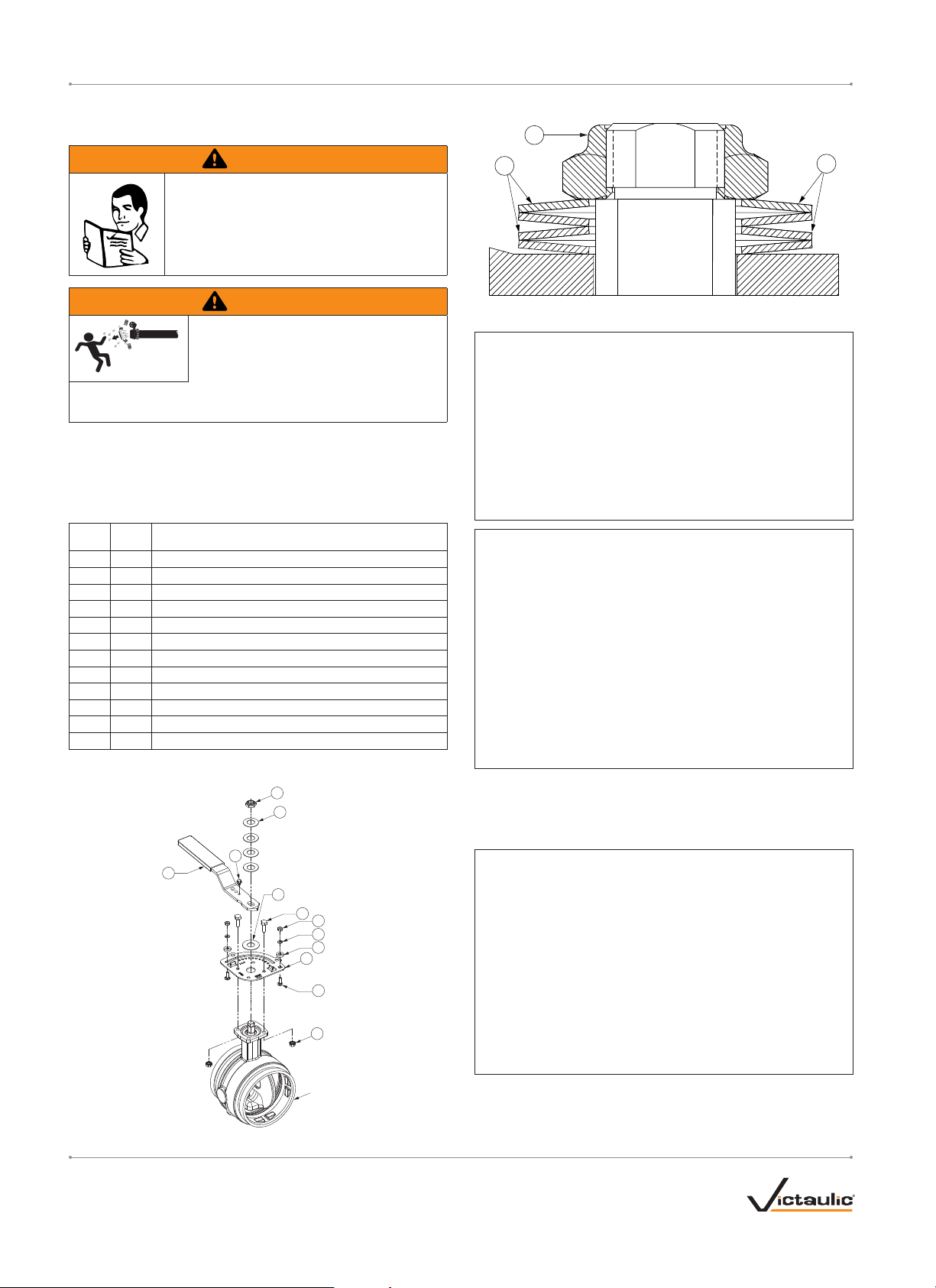
10-POSITION HANDLE PARTS LIST
Item No. Q ty. Description
1 1 Handle
2 1 Plate
3 2 Hex Nut with Captive-Toothed Lock Washer (⁄ – 18 UNC)
4 2 Round-Head, Square-Neck Bolt (¼ – 20 UNC x ¾-inch Long)
5 4 Spring Washer
6 1 Hex Lock Nut
7 2 Hex Head Screw (⁄ – 18 UNC x 1-inch Long)
8 1 Flat Washer
9 2 Lock Washer (¼ inch)
10 2 Hex Nut (¼ – 20 UNC)
11 1 Detent Screw
12 2 Memor y Stop Washer
DETAIL OF SPRING WASHERS AND LOCK NUT
7
6
Exaggerated for clarity
6
10-POSITION HANDLE ASSEMBLY DRAWING
6
5
1. Remove the hex lock nut (Item 6) from the threaded portion of the
drive hub.
2. Remove the spring washers (Item 5), handle (Item 1), and flat
washer (Item 8) from the stem assembly.
11
1
8
7
10
9
12
2
4
3
Valve Body
3. Remove the hex nuts with captive-toothed lock washers (Item 3)
from the hex-head screws (Item 7) that attach the plate (Item 2) to
the valve body mounting flange.
Exaggerated for Clarity
victaulic.com
VICTAULIC IS A REGISTERED TRADEMARK OF VICTAULIC COMPANY. © 2014 VICTAULIC COMPANY. ALL RIGHTS RESERVED.
I-VIC300MS_10
REV_F
Page 12

I-VIC300MS / Vic-300® MasterSeal™ Butterfly Valves / Installation and Maintenance Instructions
4. Remove the plate (Item 2) from the valve body mounting flange.
5. The valve is now ready for conversion to a Tamper-Resistant
Handle or a Gear Operator. In addition, the “Stem Seal
Replacement” instructions can be performed, the thermal barrier
kit can be installed, or the insulation extension kit can be installed.
CAUTION
• DO NOT attempt to operate a Series 761 or 461 Butterfly Valve
without a handle or gear operator installed.
Failure to follow this instruction will cause improper valve operation
and damage to the stem.
victaulic.com
VICTAULIC IS A REGISTERED TRADEMARK OF VICTAULIC COMPANY. © 2014 VICTAULIC COMPANY. ALL RIGHTS RESERVED.
REV_F
I-VIC300MS_11
Page 13

I-VIC300MS / Vic-300® MasterSeal™ Butterfly Valves / Installation and Maintenance Instructions
LEVER LOCK HANDLE REMOVAL FOR
8-INCH/219.1-MM VALVES
WARNING
• Read and understand all instructions before
attempting to remove the Lever Lock Handle
assembly.
Failure to follow all instructions could result in
serious personal injury and/or property damage.
WARNING
• THE PUMP MUST BE SHUT OFF to
prevent flow from passing through the
valve during the following procedures.
Failure to follow this instruction could cause product failure,
resulting in serious personal injury and/or property damage.
Removal of the Lever Lock Handle can be performed without removing
the valve from the piping system. THE PUMP MUST BE SHUT OFF to
prevent flow from passing through the valve during removal of the Lever
Lock Handle.
LEVER LOCK HANDLE PARTS LIST
Item No. Q ty. Description
1 1 Lever Lock Handle Assembly
2 1 Plate
3 2 Hex Head Screw (⁄ – 18 UNC x 1-inch Long)
4 5 Lock Washer (⁄-inch)
5 5 Hex Nut (⁄ – 18 UNC)
6 1 Hex-Head Screw (⁄ – 18 UNC x 2-inches Long)
7 1 Round-Head, Square-Neck Bolt
8 2 Flat Washer (⁄ -inch Thick x ¾-inch OD x ⁄-inch ID)
9 1 Key
LEVER LOCK HANDLE ASSEMBLY DRAWING
1
8
5
7
3
4
5
Exaggerated for clarity
4
5
4
8
3
5
4
2
6
4
5
9
Valve
Body
1. Remove the hex nut (Item 5), lock washer (Item 4), and flat washer
(Item 8) from the hex-head screw (Item 6), as shown above.
victaulic.com
VICTAULIC IS A REGISTERED TRADEMARK OF VICTAULIC COMPANY. © 2014 VICTAULIC COMPANY. ALL RIGHTS RESERVED.
I-VIC300MS_12
REV_F
Page 14

I-VIC300MS / Vic-300® MasterSeal™ Butterfly Valves / Installation and Maintenance Instructions
2. Loosen the set screw on the side of the handle (Item 1), as shown
above.
2a. Remove the Lever Lock Handle assembly from the plate.
NOTICE
• The stem contains a key that is essential for re-installation of a
handle or a gear operator. Use care to prevent misplacement of
this key.
4. Remove the plate (Item 2) from the valve body mounting flange.
5. The valve is now ready for conversion to a Tamper-Resistant
Handle or a Gear Operator. In addition, the “Stem Seal
Replacement” instructions can be performed, the thermal barrier
kit can be installed, or the insulation extension kit can be installed.
CAUTION
• DO NOT attempt to operate a Series 761 or 461 Butterfly Valve
without a handle or gear operator installed.
Failure to follow this instruction will cause improper valve operation
and damage to the stem.
3. Remove the hex nuts (Item 5) and lock washers (Item 4) from the
two hex-head screws (Item 3). In addition, remove the hex nut
(Item 5) and lock washer (Item 4) from the hex-head screw (Item
6) to permit removal of the plate from the valve body mounting
flange.
victaulic.com
VICTAULIC IS A REGISTERED TRADEMARK OF VICTAULIC COMPANY. © 2014 VICTAULIC COMPANY. ALL RIGHTS RESERVED.
REV_F
I-VIC300MS_13
Page 15

I-VIC300MS / Vic-300® MasterSeal™ Butterfly Valves / Installation and Maintenance Instructions
TAMPER-RESISTANT HANDLE KIT INSTALLATION
FOR 2 – 6-INCH/60.3 – 168.3-MM VALVES WITH
10-POSITION HANDLES
WARNING
• Read and understand all instructions before
attempting to install any Victaulic accessory
kits.
Failure to follow all instructions could result in
serious personal injury and/or property damage.
WARNING
• THE PUMP MUST BE SHUT OFF to
prevent flow from passing through the
valve during the following procedures.
Failure to follow this instruction could cause product failure,
resulting in serious personal injury and/or property damage.
The tamper-resistant handle kit can be installed without removing
the valve from the piping system. THE PUMP MUST BE SHUT OFF
to prevent flow from passing through the valve during the following
procedures.
CONTENTS OF TAMPER-RESISTANT HANDLE KIT
1. Place the disc in the fully-open or fully-closed position.
2. Remove the handle assembly by following the “10-Position Handle
Removal for 2 – 6-inch/60.3 – 168.3-mm Valves” section.
3. Install the plate (Item 2) over the stem assembly and onto the valve
body mounting flange. Make sure two holes in the plate align with
two holes in the valve body mounting flange. NOTE: If the plate
is installed incorrectly, it will not seat evenly on the valve body
mounting flange.
Item No. Q ty. Description
1 1 Tamper-Resistant Handle
2 1 Plate
3 2 Round-Head, Square-Neck Bolt (¼ – 20 UNC x ¾-inch Long)
4 4 Spring Washer
5 1 Tamper-Resistant Nut
6 2 Lock Washer (¼ inch)
7 2 Hex Nut (¼ – 20 UNC)
8 2 Self-Clinching Nut (⁄ – 18 UNC)
9 2 Breakaway Security Bolt (⁄ – 18 UNC x ¾-inch Long)
10 1 Detent Screw
11 1 Washer
12 2 Memor y Stop Washer
TAMPER-RESISTANT HANDLE ASSEMBLY DRAWING
5
4
7
6
12
11
10
8
2
1
Self-Clinching
Nuts (Item 8)
3
4. Apply Loctite 262* (or equivalent) to the two breakaway security
9
Valve
Body
Exaggerated for Clarity
victaulic.com
VICTAULIC IS A REGISTERED TRADEMARK OF VICTAULIC COMPANY. © 2014 VICTAULIC COMPANY. ALL RIGHTS RESERVED.
I-VIC300MS_14
bolts (Item 9). Insert a breakaway security bolt (Item 9) through
the two holes in the valve body mounting flange and into the plate
(Item 2) where the self-clinching nuts (Item 8) are pressed into the
plate (Item 2). Hand-tighten the breakaway security bolts (Item 9).
* Loctite is a registered trademark of the Henkel Corporation and 262 is a
trademark of the Henkel Corporation
REV_F
Page 16

I-VIC300MS / Vic-300® MasterSeal™ Butterfly Valves / Installation and Maintenance Instructions
5. Tighten the breakaway security bolts (Item 9) completely until the
hex portion breaks away, leaving a flush, tamper-resistant head.
6. Place the washer (Item 11) over the stem assembly.
5
4
4
8. Install the spring washers (Item 4) over the stem assembly. Make
sure the sets of spring washers are installed with the outside edges
touching, as shown in the drawing and photo above.
9. Apply Loctite 262* (or equivalent) to the tamper-resistant nut
(Item 5). Install the tamper-resistant nut (Item 5) onto the stem
7. Place the tamper-resistant handle (Item 1) onto the stem assembly.
Make sure the detent screw (Item 10) of the tamper-resistant
handle faces toward the detents of the plate, as shown above.
victaulic.com
VICTAULIC IS A REGISTERED TRADEMARK OF VICTAULIC COMPANY. © 2014 VICTAULIC COMPANY. ALL RIGHTS RESERVED.
REV_F
assembly.
* Loctite is a registered trademark of the Henkel Corporation and 262 is a
trademark of the Henkel Corporation
I-VIC300MS_15
Page 17

I-VIC300MS / Vic-300® MasterSeal™ Butterfly Valves / Installation and Maintenance Instructions
10. Using a spanner wrench, tighten the tamper-resistant nut (Item 5)
completely.
CAUTION
• DO NOT attempt to remove a tamper-resistant handle from the
valve.
Attempting to remove a tamper-resistant handle will cause damage
to the valve, resulting in leakage and property damage.
NOTE: The valve may be padlocked now in the open or shut position.
victaulic.com
VICTAULIC IS A REGISTERED TRADEMARK OF VICTAULIC COMPANY. © 2014 VICTAULIC COMPANY. ALL RIGHTS RESERVED.
I-VIC300MS_16
REV_F
Page 18

I-VIC300MS / Vic-300® MasterSeal™ Butterfly Valves / Installation and Maintenance Instructions
TAMPER-RESISTANT HANDLE KIT INSTALLATION
FOR 8-INCH/219.1-MM VALVES WITH LEVER
LOCK HANDLES
WARNING
• Read and understand all instructions before
attempting to install any Victaulic accessory
kits.
Failure to follow all instructions could result in
serious personal injury and/or property damage.
WARNING
• THE PUMP MUST BE SHUT OFF to
prevent flow from passing through the
valve during the following procedures.
Failure to follow this instruction could cause product failure,
resulting in serious personal injury and/or property damage.
The tamper-resistant handle kit can be installed without removing
the valve from the piping system. THE PUMP MUST BE SHUT OFF
to prevent flow from passing through the valve during the following
procedures.
CONTENTS OF TAMPER-RESISTANT HANDLE KIT
1. Place the disc in the fully-open or fully-closed position.
2. Remove the handle assembly by following the “Lever Lock Handle
Removal for 8-inch/219.1-mm Valves” section.
3. Install the plate (Item 2) over the stem assembly and onto the valve
body mounting flange. Make sure two holes in the plate align with
two holes in the valve body mounting flange. NOTE: If the plate
is installed incorrectly, it will not seat evenly on the valve body
mounting flange.
Item No. Q ty. Description
1 1 Tamper-Resistant Handle
2 1 Plate
3 1 Grooved Drive Pin
4 2 Tamper-Resistant Torx Screw (⁄ – 18 UNC x 1-inch Long)
5 2 Lock Washer (⁄-inch)
6 2 Tamper-Resistant Nut with Breakaway Hex (⁄ – 18 UNC)
7 1 Key
TAMPER-RESISTANT HANDLE ASSEMBLY DRAWING
1
3
4
5
6
4
2
5
7
Valve
Body
4. Insert a tamper-resistant torx screw (Item 4) through the two
holes in the plate and into the valve body mounting flange. Place
a lock washer (Item 5) onto the end of each tamper-resistant torx
screw, and thread a tamper-resistant nut (Item 6) onto the end of
each torx screw until hand tight. DO NOT tighten the torx screws
completely at this time.
6
5. Insert the key into the keyway in the stem. Place the tamperresistant handle (Item 1) onto the stem assembly. Make sure the
arm of the tamper-resistant handle faces toward the teeth of the
plate, as shown above.
Exaggerated for clarity
victaulic.com
VICTAULIC IS A REGISTERED TRADEMARK OF VICTAULIC COMPANY. © 2014 VICTAULIC COMPANY. ALL RIGHTS RESERVED.
REV_F
I-VIC300MS_17
Page 19

I-VIC300MS / Vic-300® MasterSeal™ Butterfly Valves / Installation and Maintenance Instructions
6. Insert the grooved drive pin (Item 3) into the hole in the tamperresistant handle, as shown above. Drive the pin completely into the
handle.
7. Tighten the set screw on the side of the handle (next to the hole
for the grooved drive pin), as shown above.
8. Close the valve disc to ensure the tamper-resistant handle makes
full contact with the flat portion of the plate that extends past the
teeth.
9. Using a tamper-resistant torx driver and an open-end wrench,
tighten the tamper-resistant nuts until the hex portion breaks away,
leaving a flush, tamper-resistant head.
NOTE: The valve may be padlocked in the open or shut position.
CAUTION
• DO NOT attempt to remove a tamper-resistant handle from the
valve.
Attempting to remove a tamper-resistant handle will cause damage
to the valve, resulting in leakage and property damage.
victaulic.com
VICTAULIC IS A REGISTERED TRADEMARK OF VICTAULIC COMPANY. © 2014 VICTAULIC COMPANY. ALL RIGHTS RESERVED.
I-VIC300MS_18
REV_F
Page 20

I-VIC300MS / Vic-300® MasterSeal™ Butterfly Valves / Installation and Maintenance Instructions
TELESCOPIC HANDLE KIT INSTALLATION FOR
10 – 12-INCH/273.0 – 323.9-MM SERIES 761
VALVES
WARNING
• Read and understand all instructions before
attempting to install any Victaulic accessory
kits.
Failure to follow all instructions could result in
serious personal injury and/or property damage.
WARNING
• THE PUMP MUST BE SHUT OFF to
prevent flow from passing through the
valve during the following procedures.
Failure to follow this instruction could cause product failure,
resulting in serious personal injury and/or property damage.
The telescopic handle kit can be installed without removing the Series
761 Butterfly Valve from the piping system. THE PUMP MUST BE
SHUT OFF to prevent flow from passing through the valve during the
following procedures.
CONTENTS OF TELESCOPIC HANDLE KIT
CONTENTS OF OPTIONAL MEMORY POINTER ASSEMBLY KIT
Item No. Qt y. Description
15 1 Memory Pointer
16 1
Carriage Bolt (⁄ – 16 UNC x 1 ¼-inches Long)
17 1 Wing Nut (⁄ – 16 UNC)
TELESCOPIC HANDLE ASSEMBLY DRAWING
U
H
T
S
N
P
O
S
H
T
U
7
5
Item No. Qt y. Description
1 1 Dial Plate
2 1 Telescopic Handle Assembly
2a 1 Sleeve
2b 1 Rod
2c 1 Knurled Ring
2d 1 Spring Pin
3 1 Handle Hub
4 1 Locking Lever
5 2
Socket Set Screw (⁄ – 18 UNC x 1 ½-inches Long)
6 1 Socket Set Screw (¼ – 20 UNC x ⁄ -inch Long)
7 2 Hex Nut (⁄ – 18 UNC)
8 1 Hex-Head Cap Screw (⁄ – 18 UNC x ½-inch Long)
9 1
Key (⁄-inch Square x 1 ⁄-inches Long)
10 2 Flat Washer (⁄-inch Diameter)
11 1
Flat Washer (1 ⁄-inches OD x ⁄-inch ID x 0.100-inch Thick)
12 4 Lock Washer (⁄-inch Diameter)
13 4 Hex-Head Cap Screw (⁄ – 16 UNC x 1-inch Long)
14 1 Carriage Bolt (⁄ – 16 UNC x 3-inches Long)
4
8
11
3
17
15
16
9
12
13
6
10
1
14
2a
2d
2c
2b
Exaggerated for clarity
1. Install the dial plate (Item 1) onto the valve so that the holes in the
dial plate align with the holes in the valve body mounting flange.
victaulic.com
VICTAULIC IS A REGISTERED TRADEMARK OF VICTAULIC COMPANY. © 2014 VICTAULIC COMPANY. ALL RIGHTS RESERVED.
REV_F
I-VIC300MS_19
Page 21

I-VIC300MS / Vic-300® MasterSeal™ Butterfly Valves / Installation and Maintenance Instructions
1a. Make sure the “OPEN” markings align with the valve inlet and
outlet.
2. Place one lock washer (Item 12) onto each of the four hex-head
cap screws (Item 13). Thread the hex-head cap screws up through
the valve body mounting flange and into the tapped bosses of the
dial plate.
5. Make sure the valve disc is in the “OPEN” position. Insert the
carriage bolt (Item 14) up through the bottom of the dial plate.
Place the two flat washers (Item 10) onto the carriage bolt.
5a. Align the pointer of the handle hub (Item 3) with the “OPEN”
position marking on the dial plate. Install the handle hub onto the
stem and carriage bolt, as shown above.
6. Install the locking lever (Item 4) onto the carriage bolt, as shown
above. DO NOT tighten the locking lever completely at this time.
3. Using a wrench, tighten the four hex-head cap screws evenly until
the lock washers become flattened.
7. Secure the handle hub to the stem with the flat washer (Item 11)
and hex-head screw (Item 8), as shown above.
8. Insert the telescopic handle assembly (Item 2) into the handle
4. Install the key (Item 9) into the keyway in the stem, as shown
above.
hub. Tighten the socket set screw (Item 6) into the handle hub to
secure the telescopic handle assembly in position.
victaulic.com
VICTAULIC IS A REGISTERED TRADEMARK OF VICTAULIC COMPANY. © 2014 VICTAULIC COMPANY. ALL RIGHTS RESERVED.
I-VIC300MS_20
REV_F
Page 22

I-VIC300MS / Vic-300® MasterSeal™ Butterfly Valves / Installation and Maintenance Instructions
9. Thread a hex nut (Item 7) onto a socket set screw (Item 5). Thread
the socket set screw halfway into the travel limit boss of the dial
plate, as shown above.
10. Make sure the valve disc is in the “OPEN” position. Turn the
socket set screw until it contacts the handle hub, as shown above.
14. After placing the valve disc in the operating position, tighten the
locking lever completely to maintain the position.
OPTIONAL MEMORY POINTER INSTALLATION
1. Using the telescopic handle, move the disc to the operating
position.
2. Insert the carriage bolt (Item 16) up through the slot in the dial
plate (adjacent to the pointer of the handle hub).
2a. Install the memory pointer (Item 15) onto the carriage bolt. Make
sure the memory pointer and the pointer of the handle hub are
aligned.
2b. Thread the wing nut (Item 17) onto the carriage bolt and tighten
completely.
11. While holding the socket set screw in position, tighten the hex nut
against the travel limit boss to set the “FULL OPEN” travel stop, as
shown above.
12. For setting the “FULL SHUT” travel stop, close the valve until the
pointer aligns with the “SHUT” marking. Thread the remaining hex
nut (Item 7) onto the socket set screw (Item 5). Thread the socket
set screw halfway into the travel limit boss on the opposite side of
the dial plate.
12a. Turn the socket set screw until it contacts the handle hub.
12b. While holding the socket set screw in position, tighten the hex nut
against the travel limit boss to set the “FULL SHUT” travel stop.
13. Place the valve back into service.
victaulic.com
VICTAULIC IS A REGISTERED TRADEMARK OF VICTAULIC COMPANY. © 2014 VICTAULIC COMPANY. ALL RIGHTS RESERVED.
REV_F
3. When the memory pointer is located at the proper position, tighten
the locking lever to maintain the position.
I-VIC300MS_21
Page 23

I-VIC300MS / Vic-300® MasterSeal™ Butterfly Valves / Installation and Maintenance Instructions
GEAR OPERATOR INSTALLATION FOR
2 – 12-INCH/60.3 – 323.9-MM VALVES
WARNING
• Read and understand all instructions before
attempting to install any Victaulic accessory
kits.
Failure to follow all instructions could result in
serious personal injury and/or property damage.
WARNING
• THE PUMP MUST BE SHUT OFF to
prevent flow from passing through the
valve during the following procedures.
Failure to follow this instruction could cause product failure,
resulting in serious personal injury and/or property damage.
The gear operator can be installed without removing the valve from the
piping system. THE PUMP MUST BE SHUT OFF to prevent flow from
passing through the valve during the following procedures.
CONTENTS OF GEAR OPERATOR KIT
GEAR OPERATOR ASSEMBLY DRAWING
2
1
5
2 – 6-inch/60.3 – 168.3-mm Sizes
6
8 – 12-inch/219.1 – 323.9-mm Sizes
Exaggerated for clarity
3
4
3
NOTE: The gear operator for a 4-inch/114.3-mm valve is shown.
Therefore, Item 4 (Key) is not shown
Item No. Q ty. Description
1 1 Gear Operator
2 1 Handwheel
3 1 Drive Bushing
4 1 Key *
5 4 Lock Washer (M8)
6 4 Hex-Head Screw (M8 x 20-mm Long)
* Not applicable for 2 – 6-inch/60.3 – 168.3-mm Sizes
NOTE: For 10-inch/273.0-mm and 12-inch/323.9-mm Series 761 and
461 Butterfly Valves, the handwheel is not attached to the shaft. To
attach the handwheel to the shaft, align the holes in the handwheel with
the holes in the shaft. Drive the roll pin (provided) completely into the
handwheel and shaft.
1. Place the valve disc in the OPEN position, and turn the handwheel
of the gear operator until the pointer is pointing toward the “OPEN”
position, as shown above. NOTE: For valves currently installed in
the system, refer to the position of the stem. For 2 – 6-inch/
60.3 – 168.3-mm sizes, the flats of the stem will be parallel to
the sides of the valve when the disc is in the “OPEN” position.
For 8 – 12-inch/219.1 – 323.9-mm sizes, the key in the stem will
face toward one end of the valve when the disc is in the “OPEN”
position.
victaulic.com
VICTAULIC IS A REGISTERED TRADEMARK OF VICTAULIC COMPANY. © 2014 VICTAULIC COMPANY. ALL RIGHTS RESERVED.
I-VIC300MS_22
REV_F
Page 24

I-VIC300MS / Vic-300® MasterSeal™ Butterfly Valves / Installation and Maintenance Instructions
2. Insert the drive bushing into the gear operator, as shown above.
Place the gear operator/drive bushing assembly on top of the valve
body by aligning the four holes of the gear operator with the four
holes in the valve body.
NOTE: For 8 – 12-inch/219.1 – 323.9-mm sizes, install the key into
the keyway in the stem. Insert the drive bushing into the gear operator.
Place the gear operator/drive bushing assembly on top of the valve body
by aligning the four holes of the gear operator with the four holes in the
valve body.
3. Install a lock washer (Item 5) onto each of the four hex-head
screws (Item 6). Thread the hex-head screws up through the holes
in the valve body mounting flange and into the gear operator.
4. Using a wrench, tighten the four hex-head screws evenly until the
lock washers become flattened.
5. Turn the handle of the gear operator to ensure proper operation.
victaulic.com
VICTAULIC IS A REGISTERED TRADEMARK OF VICTAULIC COMPANY. © 2014 VICTAULIC COMPANY. ALL RIGHTS RESERVED.
REV_F
I-VIC300MS_23
Page 25

I-VIC300MS / Vic-300® MasterSeal™ Butterfly Valves / Installation and Maintenance Instructions
ADJUSTING AND SETTING THE CLOSED TRAVEL LIMIT STOPS OF
THE GEAR OPERATOR
1. Remove the dust cap from the right side of the gear operator.
2. Loosen the hex lock nut (counterclockwise) located on the right
side of the gear operator.
3. Using an allen wrench, loosen the internal set screw approximately
three turns (counterclockwise).
4. Turn the handwheel clockwise to place the disc in the closed
(shut) position. The “closed” position is reached when the pointer
on top of the gear operator reaches the “shut” marking.
ADJUSTING AND SETTING THE OPEN TRAVEL LIMIT STOPS OF
THE GEAR OPERATOR
1. Remove the dust cap from the left side of the gear operator.
2. Loosen the hex lock nut (counterclockwise) located on the left side
of the gear operator.
3. Using an allen wrench, loosen the internal set screw approximately
three turns (counterclockwise).
4. Turn the handwheel counterclockwise to place the disc in the
open position. The “open” position is reached when the position
indicator is 90º from the correctly adjusted closed position.
5. Using the allen wrench, tighten the internal set screw (clockwise)
until it contacts the internal quadrant gear.
6. Tighten the hex lock nut (clockwise).
7. Verify proper operation of the gear operator by turning the
handwheel. Repeat steps 5 and 6, if necessary.
8. Replace the dust cap.
victaulic.com
VICTAULIC IS A REGISTERED TRADEMARK OF VICTAULIC COMPANY. © 2014 VICTAULIC COMPANY. ALL RIGHTS RESERVED.
I-VIC300MS_24
5. Using the allen wrench, tighten the internal set screw (clockwise)
until it contacts the internal quadrant gear.
6. Tighten the hex lock nut (clockwise).
7. Verify proper operation of the gear operator by turning the
handwheel. Repeat steps 5 and 6, if necessary.
8. Replace the dust cap.
REV_F
Page 26

I-VIC300MS / Vic-300® MasterSeal™ Butterfly Valves / Installation and Maintenance Instructions
MEMORY STOP KIT INSTALLATION FOR
2 – 12-INCH/60.3 – 323.9-MM GEAR OPERATED
VALVES
WARNING
• Read and understand all instructions before
attempting to install any Victaulic accessory
kits.
Failure to follow all instructions could result in
serious personal injury and/or property damage.
WARNING
• THE PUMP MUST BE SHUT OFF to
prevent flow from passing through the
valve during the following procedures.
Failure to follow this instruction could cause product failure,
resulting in serious personal injury and/or property damage.
The memory stop kit can be installed without removing the valve from
the piping system. THE PUMP MUST BE SHUT OFF to prevent flow
from passing through the valve during the following procedures.
CONTENTS OF MEMORY STOP KIT
1. Pry off the plastic position-indicator cap.
2. Remove the set screw from the top of the gear operator, as shown
above.
Item No. Qty. Description
1 1 Memory Stop
2 1 Position Indicator
3 2 Drive Pin
4 1 Bolt
5 1 Flat Washer
3. Install the memory stop onto the gear operator. Make sure the
tapped hole is centered in the slot of the memory stop, as shown
above.
victaulic.com
VICTAULIC IS A REGISTERED TRADEMARK OF VICTAULIC COMPANY. © 2014 VICTAULIC COMPANY. ALL RIGHTS RESERVED.
REV_F
I-VIC300MS_25
Page 27

I-VIC300MS / Vic-300® MasterSeal™ Butterfly Valves / Installation and Maintenance Instructions
4. Install the position indicator onto the gear operator. Make sure the
holes in the memory stop align with the holes in the gear operator.
5. Insert the drive pins into the holes in the position indicator and
gear operator. Tap the drive pins into the gear operator.
7. Slide the flat, raised por tion of the memory stop toward the
position indicator until they contact.
8. Tighten the bolt completely to maintain the position of the memory
stop.
NOTE: To re-adjust the memory stop, loosen the bolt for the memory
stop. Turn the handwheel to place the disc in the desired position
(clockwise to close and counterclockwise to open). Follow steps 7 and 8
on this page.
6. Install the bolt with the flat washer into the tapped hole in the gear
operator. Do not tighten the bolt completely at this time. Turn the
handwheel to place the disc in the desired position (clockwise to
close and counterclockwise to open).
victaulic.com
VICTAULIC IS A REGISTERED TRADEMARK OF VICTAULIC COMPANY. © 2014 VICTAULIC COMPANY. ALL RIGHTS RESERVED.
I-VIC300MS_26
REV_F
Page 28

I-VIC300MS / Vic-300® MasterSeal™ Butterfly Valves / Installation and Maintenance Instructions
THERMAL BARRIER KIT INSTALLATION FOR
2 – 12-INCH/60.3 – 323.9-MM VALVES
WARNING
• Read and understand all instructions before
attempting to install any Victaulic kits.
Failure to follow all instructions could result in
serious personal injury and/or property damage.
WARNING
• THE PUMP MUST BE SHUT OFF to
prevent flow from passing through the
valve during the following procedures.
Failure to follow this instruction could cause product failure,
resulting in serious personal injury and/or property damage.
NOTICE
• The following procedures show a typical installation of the
thermal barrier kit on a gear-operated valve. When necessary,
this thermal barrier kit can also be installed onto valves
containing Lever Lock Handles, 10-Position Handles, and
Telescopic Handles.
• The thermal barrier kit contains two gaskets. One gasket c overs
2 – 8-inch/60.3 – 219.1-mm valve sizes, and the other gasket
covers 10 – 12-inch/273.0 – 323.9-mm valve sizes. Make sure
the correct gasket size is used for the corresponding valve size.
THERMAL BARRIER KIT ASSEMBLY DRAWING
Gear
Operator
Thermal
Barrier
Gasket
Stem
Removal of the gear operator can be per formed without removing
the valve from the piping system. THE PUMP MUST BE SHUT OFF
to prevent flow from passing through the valve during the following
procedures.
Note the current orientation of the gear operator before proceeding with
the following steps. As a reference for gear operator re-installation, place
a mark on the gear operator, the stem, and the valve body mounting
flange with a permanent marker or paint pen.
1. Place the valve disc in the OPEN position by turning the
handwheel of the gear operator until the pointer is pointing toward
the OPEN position.
2. Remove the four hex-head screws and lock washers that attach
the gear operator to the valve body mounting flange.
3. Pull straight upward to remove the gear operator and drive bushing
from the valve body mounting flange. DO NOT REMOVE OR
ROTATE THE STEM.
4. Remove any debris from the valve body mounting flange.
5. Place the correct size thermal barrier gasket onto the valve body
mounting flange, as shown in the sketch on this page. NOTE: The
gasket should cover the entire valve body mounting flange ( gasket
will be slightly larger than the surface area of the valve body
mounting flange).
6. BEFORE RE-INSTALLING THE GEAR OPERATOR: Refer to the
position of the stem. For 2 – 6-inch/60.3 – 168.3-mm sizes, the
flats of the stem will be parallel to the sides of the valve when the
disc is in the OPEN position. For 8 – 12-inch/219.1 – 323.9-mm
sizes, the key in the stem will face toward one end of the valve
when the disc is in the OPEN position.
7. Insert the drive bushing into the gear operator.
8. Place the gear operator/drive bushing assembly on top of the
valve body mounting flange in the same orientation as previously
installed. Align the four holes of the gear operator with the four
holes in the valve body mounting flange.
NOTE: For 8 – 12-inch/219.1 – 323.9-mm sizes, install the key into
the keyway in the stem. Insert the drive bushing into the gear operator.
Place the gear operator/drive bushing assembly on top of the valve body
by aligning the four holes of the gear operator with the four holes in the
valve body.
9. Apply a lock washer to each of the four hex-head screws. Thread
the hex-head screws up through the valve body mounting flange
and gear operator until finger-tight.
10. Tighten the four hex-head screws evenly until the lock washers are
fully compressed and metal-to-metal contact occurs between the
gear operator and the valve body mounting flange.
11. Turn the handle of the gear operator to ensure proper operation.
Valve Body
Mounting Flange
Valve
Body
Exaggerated for clarity
victaulic.com
VICTAULIC IS A REGISTERED TRADEMARK OF VICTAULIC COMPANY. © 2014 VICTAULIC COMPANY. ALL RIGHTS RESERVED.
REV_F
I-VIC300MS_27
Page 29

I-VIC300MS / Vic-300® MasterSeal™ Butterfly Valves / Installation and Maintenance Instructions
INSULATION EXTENSION KIT FOR 2 - 8-INCH/
60.3 - 219.1-MM GEAR-OPERATED VALVES
WARNING
• Read and understand all instructions before
attempting to install any Victaulic accessory
kits.
Failure to follow all instructions could result in
serious personal injury and/or property damage.
WARNING
• THE PUMP MUST BE SHUT OFF to
prevent flow from passing through the
valve during the following procedures.
Failure to follow this instruction could cause product failure,
resulting in serious personal injury and/or property damage.
Removal of the gear operator can be per formed without removing
the valve from the piping system. THE PUMP MUST BE SHUT OFF
to prevent flow from passing through the valve during the following
procedures.
Series 761 and 461 Butterfly Valves are designed to accept 2 inches/
50 mm of insulation. When more than 2 inches/50 mm of insulation
is required, the insulation extension kit should be utilized to provide
clearance for the additional insulation.
CONTENTS OF INSULATION EXTENSION KIT
FOR GEAR-OPERATED VALVES
Quantity fo r 2 - 4-inch/
60.3 - 114.3-mm
Item
No.
1 1 1 Flat Washer
2 4 2 Spring Washer
3 1 1 Stem Adapter
4 4 4 Hex-Head Bolt
5 1 1 Spacer/Insulation Extension
6 4 4 Spring-Lock Washer
7 4 4 Hex Nut
8 0 2* Key*
9 1 1 Cup-Point Set Screw
10 1 1 L-Key Hex Wrench (Not Shown)
Sizes
Quantity fo r 5 - 8-inch/
141.3 - 219.1-mm
Sizes Description
* Key is for the 8-inch/219.1-mm valve size only
Items not called out in the drawings below are existing components that
must be saved for re-installation of the gear operator assembly.
Refer to the following page for kit installation instructions.
1
2
3
9
5
4
6
7
9
5
1
2
3
8-inch/219.1-mm
Size
4
8-inch/219.1-mm
Size
6
7
2 - 4-inch/60.3 - 114.3-mm Sizes 5 - 8-inch/141.3 - 219.1-mm Sizes
8
3
8
victaulic.com
VICTAULIC IS A REGISTERED TRADEMARK OF VICTAULIC COMPANY. © 2014 VICTAULIC COMPANY. ALL RIGHTS RESERVED.
I-VIC300MS_28
REV_F
Page 30

I-VIC300MS / Vic-300® MasterSeal™ Butterfly Valves / Installation and Maintenance Instructions
INSULATION EXTENSION KIT INSTALLATION
FOR 2 – 8-INCH/60.3 – 219.1-MM
GEAR-OPERATED VALVES
WARNING
• Read and understand all instructions before
attempting to install any Victaulic accessory
kits.
Failure to follow all instructions could result in
serious personal injury and/or property damage.
Spring
Washers
Exaggerated for Clarity
9. FOR 2 - 4-INCH/60.3 - 114.3-MM VALVES ONLY: Install the four
spring washers (Item 2) onto the stem assembly. Make sure the
sets of spring washers (Item 2) are installed with the outside edges
touching, as shown in the drawing above.
Flat
Washer
WARNING
• THE PUMP MUST BE SHUT OFF to
prevent flow from passing through the
valve during the following procedures.
Failure to follow this instruction could cause product failure,
resulting in serious personal injury and/or property damage.
Removal of the gear operator can be per formed without removing
the valve from the piping system. THE PUMP MUST BE SHUT OFF
to prevent flow from passing through the valve during the following
procedures.
Note the current orientation of the gear operator before proceeding
with the following steps. AS A REFERENCE FOR GEAR OPERATOR
RE-INSTALLATION: Place a mark on the gear operator, the stem, and
the valve body mounting flange with a permanent marker or paint pen.
1. Place the valve disc in the OPEN position by turning the
handwheel of the gear operator until the pointer is pointing toward
the OPEN position.
2. Remove the four existing hex-head screws and lock washers
that attach the gear operator to the valve body mounting flange.
NOTE: These hex-head screws and lock washers are required for
re-installation.
3. Pull straight upward to remove the gear operator and existing drive
bushing from the valve body mounting flange. These items are
required for re-installation. DO NOT REMOVE OR ROTATE THE
STEM.
4. Remove any debris from the valve body mounting flange.
5. Place the stem adapter (Item 3) onto the stem. NOTE: For
8-inch/219.1-mm valves, remove the existing key from the keyway
in the stem. Install a new key (Item 8), provided in the kit, into the
keyway in the stem. Install the second key (Item 8), provided in the
kit, into the stem adapter (Item 3).
6. Using the L-key hex wrench (provided with the kit), drive the cuppoint set screw (Item 9) into the threaded hole in the stem adapter
(Item 3).
7. Place the spacer/insulation extension (Item 5) onto the valve body
mounting flange with the machined counterbore facing upward
(away from the valve). Align the four holes of the spacer/insulation
extension (Item 5) with the four holes in the valve body mounting
flange.
8. Secure the spacer/insulation extension (Item 5) to the valve body
mounting flange by using the four hex-head bolts, spring-lock
washers and hex nuts (Items 4, 6, and 7) provided in the kit.
Flat
Washer
Spring
Washers
Exaggerated for Clarity
9a. FOR 5 - 8-INCH/141.3 - 219.1-MM VALVES ONLY: Install the
two spring washers (Item 2) onto the stem assembly. Make sure
the spring washers (Item 2) are installed with the outside edges
touching, as shown in the drawing above.
10. Place the flat washer (Item 1) on top of the spring washers
(Item 2).
11. Insert the existing drive bushing into the gear operator. NOTE: For
8-inch/219.1-mm valves, make sure the existing key is installed
in the keyway in the stem. Insert the drive bushing into the gear
operator.
12. Place the gear operator assembly onto the valve body mounting
flange in the same orientation as previously installed. Insert the
four existing hex-head screws with lock washers (removed in step
2) into the holes in the spacer/insulation extension and into the
gear operator assembly.
13. Using a wrench, tighten the four hex-head screws evenly until the
lock washers become flattened.
14. Turn the handle of the gear operator to ensure proper operation.
victaulic.com
VICTAULIC IS A REGISTERED TRADEMARK OF VICTAULIC COMPANY. © 2014 VICTAULIC COMPANY. ALL RIGHTS RESERVED.
REV_F
I-VIC300MS_29
Page 31

I-VIC300MS / Vic-300® MasterSeal™ Butterfly Valves / Installation and Maintenance Instructions
INSULATION EXTENSION KIT FOR 2 - 6-INCH/
60.3 - 168.3-MM VALVES WITH 10-POSITION
HANDLES
WARNING
• Read and understand all instructions before
attempting to install any Victaulic accessory
kits.
Failure to follow all instructions could result in
serious personal injury and/or property damage.
WARNING
• THE PUMP MUST BE SHUT OFF to
prevent flow from passing through the
valve during the following procedures.
Failure to follow this instruction could cause product failure,
resulting in serious personal injury and/or property damage.
Removal of the 10-Position Handle can be performed without removing
the valve from the piping system. THE PUMP MUST BE SHUT OFF
to prevent flow from passing through the valve during the following
procedures.
Series 761 and 461 Butterfly Valves are designed to accept 2 inches/
50 mm of insulation. When more than 2 inches/50 mm of insulation
is required, the insulation extension kit should be utilized to provide
clearance for the additional insulation.
CONTENTS OF INSULATION EXTENSION KIT
FOR VALVES WITH 10-POSITION HANDLES
Item No. Quantity Description
1 1 Flat Washer
2 1 Stem Adapter
3 1 Spacer/Insulation Extension
4 4 Hex-Head Bolt
5 4 Spring-Lock Washer
6 4 Hex Nut
7 1 Cup-Point Set Screw
8 1 L-Key Hex Wrench (Not Shown)
Items not called out in the drawings below are existing components that
must be saved for re-installation of the 10-Position Handle assembly.
Refer to the following page for kit installation instructions.
1
3
7
2
4
5
6
2 - 6-inch/60.3 - 168.3-mm Sizes
victaulic.com
VICTAULIC IS A REGISTERED TRADEMARK OF VICTAULIC COMPANY. © 2014 VICTAULIC COMPANY. ALL RIGHTS RESERVED.
I-VIC300MS_30
REV_F
Page 32

I-VIC300MS / Vic-300® MasterSeal™ Butterfly Valves / Installation and Maintenance Instructions
Exaggerated for clarity
INSULATION EXTENSION KIT INSTALLATION
FOR 2 – 6-INCH/60.3 – 168.3-MM VALVES WITH
10-POSITION HANDLES
WARNING
• Read and understand all instructions before
attempting to install any Victaulic accessory
kits.
Failure to follow all instructions could result in
serious personal injury and/or property damage.
WARNING
• THE PUMP MUST BE SHUT OFF to
prevent flow from passing through the
valve during the following procedures.
Failure to follow this instruction could cause product failure,
resulting in serious personal injury and/or property damage.
Removal of the 10-Position Handle can be performed without removing
the valve from the piping system. THE PUMP MUST BE SHUT OFF
to prevent flow from passing through the valve during the following
procedures.
1. Using the handle, place the valve disc in the OPEN position.
NOTE: Using a paint stick or bright-colored marker, place a mark
on the handle plate and the valve body to aid in re-installing the
handle plate in the correct orientation.
2. Follow the “10-Position Handle Removal for 2 - 6-inch/
60.3 - 168.3-mm Valves” section in this manual to remove the
handle assembly from the valve. NOTE: All components removed
from the valve will be required for re-installation.
3. Remove any debris from the valve body mounting flange.
4. Place the stem adapter (Item 2) onto the stem.
5. Using the L-key hex wrench (provided with the kit), drive the cuppoint set screw (Item 7) into the threaded hole in the stem adapter
(Item 2).
6. Place the spacer/insulation extension (Item 3) onto the valve
body mounting flange with the machined counterbore facing
upward (away from the valve). Make sure the contoured ends of
the spacer/insulation extension (Item 3) are matched up to the
contoured ends of the valve body mounting flange, and align the
four holes.
7. Secure the spacer/insulation extension (Item 3) to the valve body
mounting flange by using the four hex-head bolts, spring-lock
washers and hex nuts (Items 4, 5, and 6) provided in the kit.
8. Place the flat washer (Item 1), provided in the kit, into the
counterbore of the spacer/insulation extension (Item 3).
9. Place the existing handle plate onto the spacer/insulation extension
(Item 3). Make sure the mark on the handle plate (made in step 1)
is aligned with the mark on the valve body (made in step 1).
10. Insert an existing hex-head screw through the holes in the existing
handle plate and into the spacer/insulation extension (Item 3).
11. Install an existing hex nut with captive-toothed lock washer onto
the existing hex-head screws.
12. Tighten the hex nuts with captive-toothed lock washer to secure
the existing handle plate to the spacer/insulation extension (Item 3).
13. Place the existing flat washer over the stem adapter (Item 2) and
onto the existing handle plate.
14. Install the existing 10-Position Handle onto the stem adapter (Item
2). Make sure the pointer of the handle is pointing to the OPEN
marking on the plate.
7
6
15. Install the existing spring washers onto the stem adapter (Item 2).
Make sure the sets of spring washers are installed with the outside
edges touching, as shown in the drawing and photo above.
15a. Install the existing lock nut onto the stem adapter (Item 2). Using a
wrench, tighten the lock nut completely to secure the 10-Position
Handle to the stem adapter (Item 2).
16. Turn the 10-Position Handle to ensure proper operation.
6
victaulic.com
VICTAULIC IS A REGISTERED TRADEMARK OF VICTAULIC COMPANY. © 2014 VICTAULIC COMPANY. ALL RIGHTS RESERVED.
REV_F
I-VIC300MS_31
Page 33

I-VIC300MS / Vic-300® MasterSeal™ Butterfly Valves / Installation and Maintenance Instructions
INSULATION EXTENSION KIT FOR 8-INCH/
219.1-MM VALVES WITH LEVER LOCK HANDLES
WARNING
• Read and understand all instructions before
attempting to install any Victaulic accessory
kits.
Failure to follow all instructions could result in
serious personal injury and/or property damage.
WARNING
• THE PUMP MUST BE SHUT OFF to
prevent flow from passing through the
valve during the following procedures.
Failure to follow this instruction could cause product failure,
resulting in serious personal injury and/or property damage.
Removal of the Lever Lock Handle can be performed without removing
the valve from the piping system. THE PUMP MUST BE SHUT OFF
to prevent flow from passing through the valve during the following
procedures.
Series 761 and 461 Butterfly Valves are designed to accept 2 inches/
50 mm of insulation. When more than 2 inches/50 mm of insulation
is required, the insulation extension kit should be utilized to provide
clearance for the additional insulation.
CONTENTS OF INSULATION EXTENSION KIT
FOR VALVES WITH LEVER LOCK HANDLES
Item No. Quantity Description
1 2 Key
2 1 Stem Adapter
3 1 Spacer/Insulation Ex tension
4 4 Hex-Head Bolt
5 4 Spring-Lock Washer
6 4 Hex Nut
Items not called out in the drawings below are existing components that
must be saved for re-installation of the Lever Lock Handle assembly.
Refer to the following page for kit installation instructions.
3
2
8-inch/219.1-mm Size
1
4
5
6
1
victaulic.com
VICTAULIC IS A REGISTERED TRADEMARK OF VICTAULIC COMPANY. © 2014 VICTAULIC COMPANY. ALL RIGHTS RESERVED.
I-VIC300MS_32
REV_F
Page 34

I-VIC300MS / Vic-300® MasterSeal™ Butterfly Valves / Installation and Maintenance Instructions
INSULATION EXTENSION KIT INSTALLATION
FOR 8-INCH/219.1-MM VALVES WITH LEVER
LOCK HANDLES
WARNING
• Read and understand all instructions before
attempting to install any Victaulic accessory
kits.
Failure to follow all instructions could result in
serious personal injury and/or property damage.
WARNING
• THE PUMP MUST BE SHUT OFF to
prevent flow from passing through the
valve during the following procedures.
Failure to follow this instruction could cause product failure,
resulting in serious personal injury and/or property damage.
Removal of the Lever Lock Handle can be performed without removing
the valve from the piping system. THE PUMP MUST BE SHUT OFF
to prevent flow from passing through the valve during the following
procedures.
1. Using the handle, place the valve disc in the OPEN position.
NOTE: Using a paint stick or bright-colored marker, place a mark
on the handle plate and the valve body to aid in re-installing the
handle plate in the correct orientation.
2. Follow the “Lever Lock Handle Removal for 8-inch/219.1-mm
Valves” section in this manual to remove the handle assembly from
the valve. NOTE: The memory stop hardware does not need to be
removed in order to remove the handle. All components removed
from the valve will be required for re-installation.
3. Remove any debris from the valve body mounting flange.
4. Remove the existing key from the keyway in the stem. Install a new
key (Item 1), provided in the kit, into the keyway in the stem.
5. Place the stem adapter (Item 2) onto the stem.
6. Place the spacer/insulation extension (Item 3) onto the valve
body mounting flange with the machined counterbore facing
upward (away from the valve). Make sure the contoured ends of
the spacer/insulation extension (Item 3) are matched up to the
contoured ends of the valve body mounting flange, and align the
four holes.
7. Secure the spacer/insulation extension (Item 3) to the valve body
mounting flange by using the four hex-head bolts, spring-lock
washers and hex nuts (Items 4, 5, and 6) provided in the kit.
8. Place the existing handle plate onto the spacer/insulation extension
(Item 3). Make sure the mark on the handle plate (made in step 1)
is aligned with the mark on the valve body (made in step 1).
Existing Memory
Stop Hardware
Existing Flat
Existing
Lever Lock
Handle
Existing Hex-Head Screws
⁄ - 18 UNC x 1-inch Long
Handle
Plate
Existing Lock
Washer and
Hex Nut
9. Insert the existing 5/16 - 18 UNC x 2-inch long hex-head screw up
through the hole in the spacer/insulation extension (Item 3) and
the hole in the existing handle plate designated in the drawing
above. Install an existing lock washer and existing hex nut onto this
hex-head screw. Using a wrench, tighten the hex nut until the lock
washer becomes flattened.
10. Install the two 5/16 - 18 UNC x 1-inch long hex-head screws into
the existing handle plate and down through the two holes in the
spacer/insulation extension (Item 3) designated in the drawing
above. Install an existing lock washer and hex nut onto these hexhead screws. Using a wrench, tighten the hex nuts until the lock
washers become flattened.
11. Install the second key (Item 1), provided in the kit, into the keyway
of the stem adapter (Item 2).
12. Install the existing Lever Lock Handle assembly onto the stem
adapter (Item 2). Make sure the pointer of the handle is pointing to
the OPEN marking on the handle plate.
{
Washer, Lock
Washer, and
{
Hex Nut
Existing Lock
Washer and
{
Hex Nut
Existing Lock
Washer and
{
Hex Nut
Existing
Hex-Head Screw
⁄ - 18 UNC x
2-inches Long
13. Tighten the set screw on the side of the Lever Lock Handle, as
shown above.
14. Install the existing flat washer, lock washer, and hex nut onto the
5/16 - 18 UNC x 2-inch long hex-head screw installed in step 9.
Using a wrench, tighten the hex nut until the lock washer becomes
flattened.
15. Turn the Lever Lock Handle to ensure proper operation.
victaulic.com
VICTAULIC IS A REGISTERED TRADEMARK OF VICTAULIC COMPANY. © 2014 VICTAULIC COMPANY. ALL RIGHTS RESERVED.
REV_F
I-VIC300MS_33
Page 35

Series 761 Vic-300® MasterSeal™ Carbon Steel Butterfly Valve
Series 461 Vic-300
®
MasterSeal™ Stainless Steel Butterfly Valve
I-VIC300MSINSTALLATION AND MAINTENANCE INSTRUCTIONS
For complete contact information, visit www.victaulic.com
I-VIC300MS 3905 REV F UPDATED 05/2014 Z000300MS0
VICTAULIC IS A REGISTERED TRADEMARK OF VICTAULIC COMPANY. © 2014 VICTAULIC COMPANY. ALL RIGHTS RESERVED.
I-VIC300MS
 Loading...