

Page 1
R
Operating and Maintenance
Instructions Manual
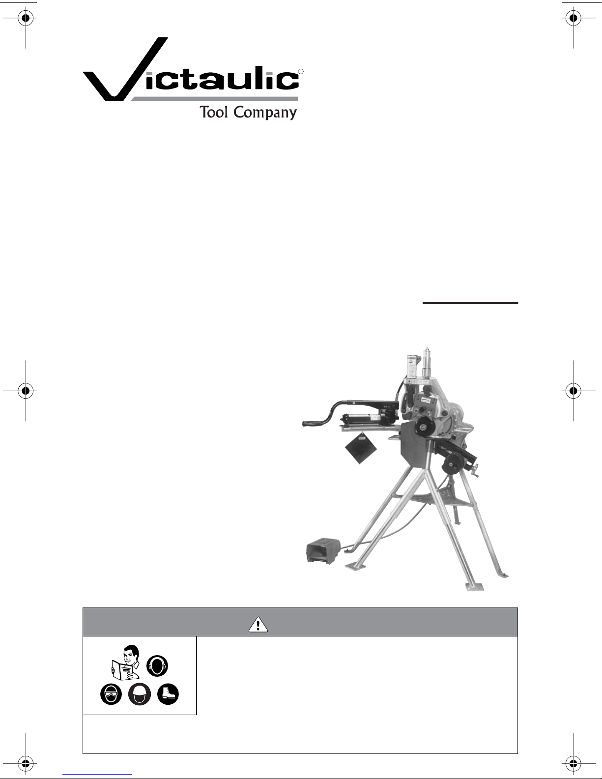
VE272SFS
Pipe/Tubing Roll Grooving Tool
Failure to follow instructions and warnings could result in serious personal injury,
property damage, and/or product damage.
• Before operating or servicing the VE272SFS Roll Grooving Tool, read all instruc-
• Wear safety glasses, hardhat, foot protection, and hearing protection.
• Save this operating and maintenance manual.
If you need additional copies of any literature, or if you have questions concerning the safe and proper operation of
this tool, contact Victaulic Tool Company, P.O. Box 31, Easton, PA 18044-0031, Phone: 1-800-PICK VIC, e-mail:
pickvic@victaulic.com.
WARNING
tions in this manual and all warning labels on the tool.
Page 2

Page 3

INDEX
Hazard Identification . . . . . . . . . . . . . . . . . 2
Operator Safety Instructions . . . . . . . . . . 3
Introduction . . . . . . . . . . . . . . . . . . . . . . . . 4
Receiving the Tool
VE272SFS Container Contents
Power Requirements. . . . . . . . . . . . . . . . . 5
Power Drive
Extension Cord Requirements
Tool Nomenclature . . . . . . . . . . . . . . . . . . 6
Tool Setup . . . . . . . . . . . . . . . . . . . . . . . . . 7
Pre-Operation Checks
and Adjustments . . . . . . . . . . . . . . . . . . . 11
Grooving Rolls
Pipe/Tubing Preparation
Groovable Pipe/Tubing Lengths . . . . . . 11
Short Pipe/Tubing Lengths
Long Pipe/Tubing Lengths
Roll Guard Adjustment . . . . . . . . . . . . . . 14
Pipe Stablizer Adjustment16
Groove Diameter Stop Adjustment . . . . 18
Grooving Operation . . . . . . . . . . . . . . . . 20
Roll Changing . . . . . . . . . . . . . . . . . . . . . 23
Lower Roll Removal
for 2-inch and Larger Sizes . . . . . . . . . . 24
Upper Roll Removal . . . . . . . . . . . . . . . . 25
Arbor Removal. . . . . . . . . . . . . . . . . . . . . 26
Lower Roll/Adapter Assembly
Installation for 3/4-inch and
1 – 11/2-inch Sizes . . . . . . . . . . . . . . . . . . 27
Upper Roll Installation . . . . . . . . . . . . . . 28
Lower Roll/Adapter Assembly Removal
for 3/4-inch and 1 – 11/2-inch Sizes . . . . . 29
Arbor Installation. . . . . . . . . . . . . . . . . . . 29
Lower Roll Installation
for 2-inch and Larger Sizes . . . . . . . . . . 30
Maintenance. . . . . . . . . . . . . . . . . . . . . . . 32
Lubrication
Checking and Filling
Hydraulic Systems
Air Bleeding
. . . . . . . . . . . . . . . . . . . . . . . 32
. . . . . . . . . . . . . . . . . . 4
. . . . . . . . 5
. . . . . . . . . . . . . . . . . . . . . . . 5
. . . . . . . . . 5
. . . . . . . . . . . . . . . . . . . . 11
. . . . . . . . . . . . 11
. . . . . . . . . . 12
. . . . . . . . . . 13
. . . . . . . . . . . . . . . 33
. . . . . . . . . . . . . . . . . . . . . . 34
Parts Ordering Information . . . . . . . . . . . 35
Accessories 35
VAPS 112 Victaulic Adjustable
Pipe Stand
VAPS 224 Victaulic Adjustable
Pipe Stand
VPD752 Power Drive
Stabilizer Assembly
Optional Rolls
Troubleshooting . . . . . . . . . . . . . . . . . . . . 37
Tool Rating and Roll Selection . . . . . . . . 39
Standard and “ES” Rolls for
Steel and Stainless Steel Pipe –
Color-Coded Black
Rolls for Aluminum and PVC Plastic
Pipe – Color-Coded Yellow Zinc
RX Rolls for Schedule 5S and 10S
Stainless Steel Pipe –
Color-Coded Silver
Rolls for CTS US Standard -
ASTM Drawn Copper Tubing –
Color-Coded Copper
Rolls for European Standard –
EN 1057 Drawn Copper Tubing –
Color-Coded Copper
Rolls for Australian Standard –
AS 1432 Drawn Copper Tubing –
Color Coded Copper
Explanation of Critical Roll
Groove Dimensions . . . . . . . . . . . . . . . . . 44
Roll Groove Specifications . . . . . . . . . . . 45
Steel, Stainless Steel, Aluminum,
and PVC Pipe
Steel Pipe and All Materials
Grooved with “ES” Rolls
Copper Tubing to CTS US Standard –
ASTM B-88 and ASTM B-306
Copper Tubing to European
Standard – EN 1057
Copper Tubing to Australian
Standard – AS 1432
Facilities Locations . . . . . . . . . . . . . . . . B/C
. . . . . . . . . . . . . . . . . . . . . . 35
. . . . . . . . . . . . . . . . . . . . . . 35
. . . . . . . . . . . . . . . 35
. . . . . . . . . . . . . . . . 36
. . . . . . . . . . . . . . . . . . . . . 36
. . . . . . . . . . . . . . . 39
. . . . . 40
. . . . . . . . . . . . . . . 41
. . . . . . . . . . . . . . 42
. . . . . . . . . . . . . . 42
. . . . . . . . . . . . . . 43
. . . . . . . . . . . . . . . . . . . . 45
. . . . . . . . . . . . 47
. . . . . . . 48
. . . . . . . . . . . . . . . 49
. . . . . . . . . . . . . . . 49
VE272SFS Roll Grooving Tool 1
Page 4

HAZARD IDENTIFICATION
Definitions for identifying the various hazard
levels are provided below.
This safety alert symbol indicates
important safety messages. When
you see this symbol, be alert to the
possibility of personal injury. Carefully read
and fully understand the message that follows.
DANGER
• The use of the word “DANGER” identifies an immediate hazard with a likelihood of death or serious
personal injury if instructions, including recommended precautions, are not followed.
WARNING
• The use of the word “WARNING” identifies the presence of hazards or unsafe practices that could
result in death or serious personal injury if instructions, including recommended precautions, are not
followed.
CAUTION
• The use of the word “CAUTION” identifies possible
hazards or unsafe practices that could result in personal injury and product or property damage if
instructions, including recommended precautions,
are not followed.
NOTICE
• The use of the word “NOTICE” identifies special
instructions that are important but not related to
hazards.
2 VE272SFS Roll Grooving Tool
Page 5

OPERATOR SAFETY INSTRUCTIONS
The VE272SFS is designed only for roll grooving pipe/tubing. Use of this tool requires dexterity and mechanical skills, as well as sound
safety habits. Although this tool is manufactured for safe, dependable operation, it is impossible to anticipate all the combinations of
circumstances that could result in an accident. The following instructions are recommended for safe operation of this tool. The
operator is cautioned to always practice
“safety first” during each phase of use, including setup and maintenance. It is the responsibility of the owner, lessee, or user of this tool
to ensure that all operators read this manual
and fully understand the operation of this tool.
Read this manual before operating or servicing this tool. Become familiar with the tool’s
operations, applications, and limitations. Be
particularly aware of its specific hazards.
Store this manual in a clean area where it is
always readily available. Additional copies of
this manual are available upon request
through the Victaulic Tool Company.
1.
This tool is designed ONLY for roll
grooving pipe/tubing sizes, materials, and
wall thicknesses listed in the "Tool Rating
and Roll Selection" section, starting on
page 39.
2.
Avoid using the tool in dangerous environments.
and do not use the tool in damp or wet locations. Do not use the tool on sloped or uneven
surfaces. Keep the work area well lit. Allow
sufficient space to operate the tool properly.
3.
Ground the power drive to protect the
operator from electric shock.
power drive is connected to an internally
grounded electrical source.
4.
Prevent back injury.
two people are needed to safely handle the
tool head assembly. Use a hoist to lift the tool
head assembly into position.
5.
Inspect the equipment.
the tool, check all moveable parts for any obstructions. Make sure guards and tool components are installed and adjusted properly.
Do not expose the tool to rain,
Make sure the
During tool setup,
Before using
6.
Prevent accidental startups.
switch on the power drive to the “OFF” position before plugging the unit into the electrical
source.
7.
Wear proper apparel.
clothing, jewelry, or anything that can become
entangled in moving parts.
8.
Wear protective items when working
with tools.
hardhat, foot protection, and hearing protection.
9.
are drowsy from medication or fatigue. Avoid
horseplay around the equipment.
10.
ate work area.
safe distance from the equipment at all times.
11.
area around the tool clear of any obstructions
that could limit the movement of the operator.
Clean up any oil or other spills.
12.
sories.
fer to the "Tool Setup" section on page 7.
13.
tubing lengths with a pipe stand that is secured to the floor or the ground.
14.
switch.
with a safety foot switch that is located for
easy operator access. Never reach across
moving parts. If the power drive does not contain a safety foot switch, contact the power
drive manufacturer.
15.
grooving rolls and stabilizer wheel during
the grooving operation.
crush or cut fingers and hands.
16.
end during tool operation.
Always wear safety glasses,
Stay alert.
Keep visitors away from the immedi-
Keep work areas clean.
Secure the work, machine, and acces-
Make sure the machine is stable. Re-
Support the work.
Operate the tool only with a safety foot
The power drive must be operated
Keep hands and tools away from
Do not reach inside the pipe/tubing
Do not operate the tool if you
All visitors should be kept a
Do not wear loose
Support long pipe/
Grooving rolls can
Place the
Keep the work
VE272SFS Roll Grooving Tool 3
Page 6
17.
Do not over-reach.
footing and balance at all times. Make sure
the safety foot switch is easily accessible for
the operator.
18.
Do not force the tool.
tool or accessories to perform any functions
beyond their capabilities. Do not overload the
tool.
19.
Do not operate the tool at speeds exceeding those specified in this manual.
Maintain proper
Do not force the
INTRODUCTION
NOTICE
• Drawings and/or pictures in this manual may be
exaggerated for clarity.
• The tool, along with this operating and maintenance
instructions manual, contains trademarks, copyrights, and/or patented features that are the exclusive property of Victaulic Company.
20.
Do not abuse the foot switch cord.
Never yank the cord out of the receptacle.
Keep the cord away from heat, oil, and sharp
objects.
21.
Unplug the power drive from the elec-
trical source before servicing the tool.
authorized personnel should attempt to perform maintenance on the tool. Always disconnect the power drive from the electrical
source before servicing or adjusting the tool.
22.
Maintain tools with care.
clean at all times to ensure proper and safe
performance. Follow the instructions for lubricating tool components.
23.
When tools are not is use, store them
in a dry, secure place.
24.
Use only Victaulic replacement parts
and accessories.
result in a voided warranty, improper operation, and hazardous situations. Refer to the
“Parts Ordering Information” and “Accessories” sections on page 35.
25.
Do not remove any labels from the
tool.
Replace any damaged or worn labels.
Use of any other parts may
Keep tools
Only
The Victaulic VE272SFS tool is a semi-automated, hydraulic feed tool for roll grooving
pipe/tubing to receive Victaulic grooved pipe/
tubing products. The standard VE272SFS tool
is supplied with grooving rolls for 2 – 12-inch
steel pipe. Rolls are marked with the size and
part number, and they are color coded to
identify the pipe/tubing material. For roll
grooving to other specifications and materials, refer to the Tool Rating and Roll Selection
on page 39. Grooving rolls for other specifications, sizes, and materials must be purchased
separately.
CAUTION
• This tool must be used ONLY for roll grooving pipe/
tubing designated in the “Tool Rating and Roll
Selection” section of this manual.
Failure to follow this instruction could overload the
tool, resulting in reduced tool life and/or damage to
the tool.
RECEIVING THE TOOL
VE272SFS tools are packed individually in
sturdy containers, which are designed for use
in re-shipping tools back to Victaulic upon
completion of the rental contract, when applicable.
4 VE272SFS Roll Grooving Tool
Upon receipt of the tool, make sure all necessary parts are included. If any parts are missing, notify the Victaulic Tool Company.
Page 7
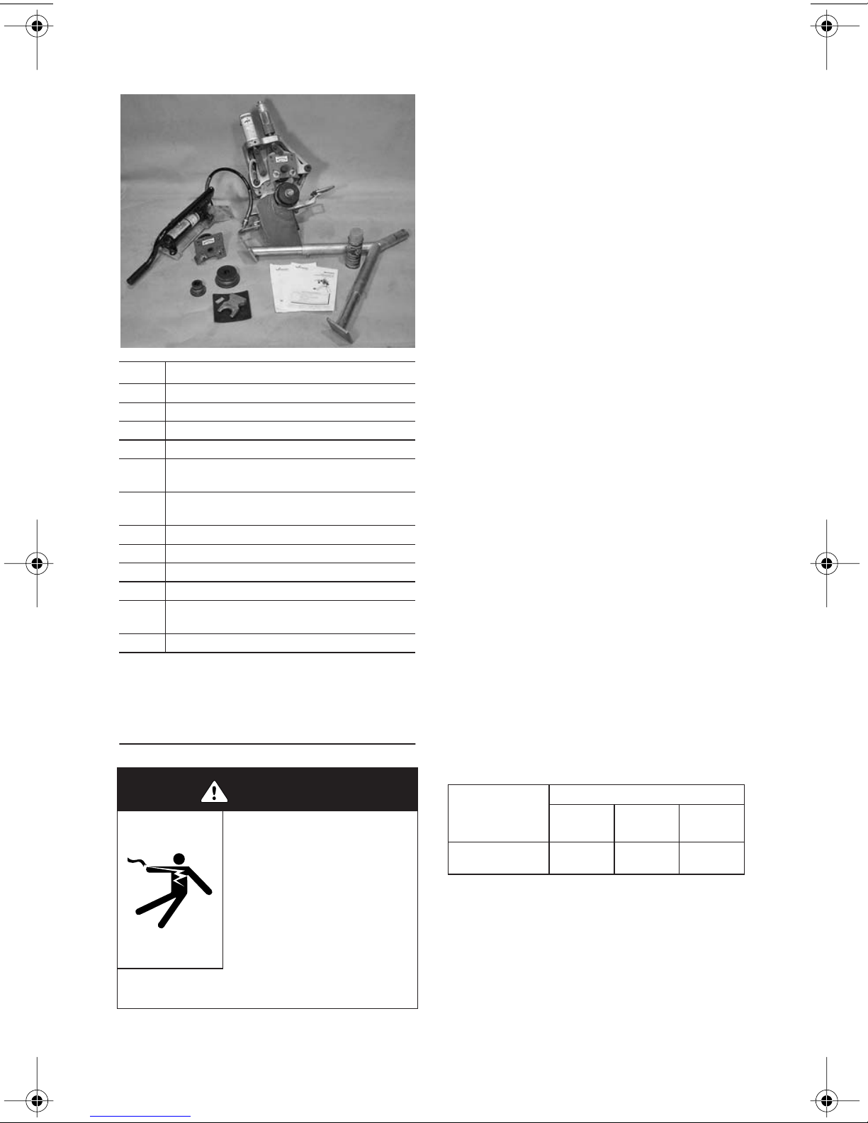
VE272SFS CONTAINER
CONTENTS
Qty. Description
1 Tool Head with Mounting Table
1 Upper Leg
2 Adjustable Legs
1 Hand Pump/Pump Support
Upper Rolls for 2 – 6-inch Steel Pipe and
2
8 – 12-inch Steel Pipe
“Keyless” Lower Rolls for 2 – 3-inch, 4 –
3
6-inch, and 8 – 12-inch Steel Pipe ‡
1 Guard Setting Pad
1 Lower Roll Removal Wedge
1 Can of Dry Graphite Spray
1 Pipe Tape
VE272SFS Operating and Maintenance
2
Instructions Manual
1 RP-272SFS Repair Parts List
NOTE:
bly, may be shipped separately.
‡ The 8 – 12-inch roll set is mounted on the tool head
assembly at the factory.
Optional items, such as the stabilizer assem-
POWER REQUIREMENTS
POWER DRIVE
VE272SFS tools are designed for operation
with a power drive. Tools mount directly onto
a Victaulic VPD752 Power Drive or a Ridgid®
300 Power Drive with a 38-rpm maximum
chuck speed.
Power must be supplied to the power drive
through a safety foot switch to ensure safe operation. Make sure the power drive is properly
grounded in accordance with Article 250 of
the National Electrical Code.
If an extension cord is required, refer to the
“Extension Cord Requirements” section on
this page for cord sizes. In addition, refer to
the power drive manufacturer’s instructions
prior to use.
EXTENSION CORD REQUIREMENTS
When pre-wired outlets are not available and
an extension cord must be used, it is important to use the proper cord size (i.e. Conductor Size American Wire Gauge). Cord size
selection is based upon tool rating (amps)
and cord length (feet). Use of a cord size
(gauge) thinner than required will cause significant voltage drop at the power drive while
the tool is operating. Voltage drops may
cause damage to the power drive and can result in improper tool operation.
ceptable to use a cord size (gauge) that is
heavier than required.
The required cord sizes (gauges) for cord
lengths up to and including 100 feet (31 m)
are listed in the table below. Use of extension
cords longer than 100 feet (31 m) must be
avoided.
NOTE:
It is ac-
DANGER
• To reduce the risk of electric
shock, check the electrical
source for proper grounding.
• Before performing any maintenance on the tool, turn the
switch on the power drive to the
“OFF” position, or disconnect
the power cord from the electrical source.
Failure to follow these instructions could result in
death or serious personal injury.
VE272SFS Roll Grooving Tool 5
Cord Lengths
Power Drive Rating
Volts (Amps)
115
(15)
®
Ridgid is a registered trademark of the Ridge Tool
Company.
25 feet
(8 m)
12 gauge 12 gauge 10 gauge
50 feet
(15 m)
100 feet
(31 m)
Page 8
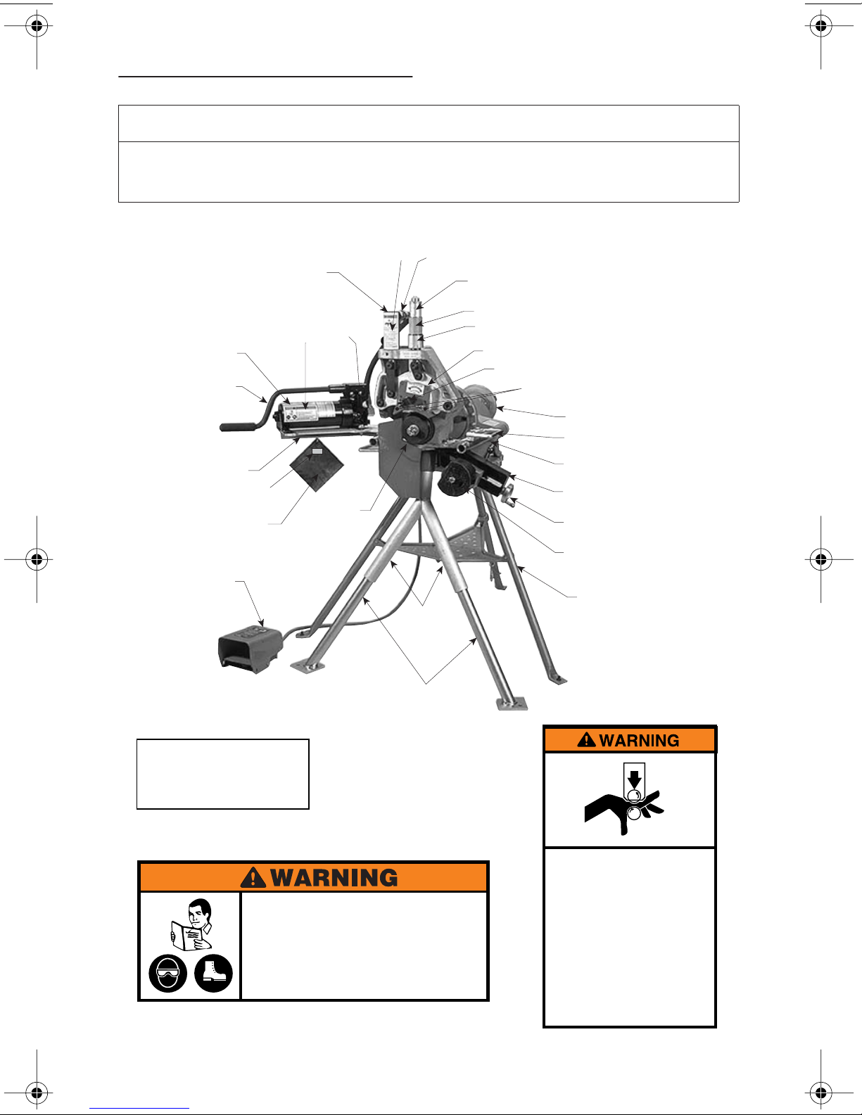
TOOL NOMENCLATURE
NOTICE
• Drawings and/or pictures in this manual may be exaggerated for clarity.
• The tool, along with this operating and maintenance instructions manual, contains trademarks, copyrights, and/or
patented features that are the exclusive property of Victaulic Company.
Hydraulic
➀
Connectors
Upper Leg
Pipe Size
Indicator
Depth Adjuster
Depth
Adjuster Lock
Upper Roll Assembly
Upper Roll Bolt
Roll Guards
Power Drive
Lifting Handles
Power Drive
Support Arms
Pipe Stabilizer Assembly
(optional)
Pipe Stabilizer
Handwheel
Stabilizer
Roller
Power Drive
Stand
Pump
Pump
Handle
Pump
Support
Guard
Setting Pad
Power Drive Safety
Foot Switch
➂
Hydraulic
Cylinder
➁
Pump
Val ve
Lower Roll
➂
ALWAYS KEEP THIS PAD WITH THE
TOOL. USE IT TO SET THE GUARDS
IN ACCORDANCE WITH THE TOOL
OPERATION AND MAINTENANCE
MANUAL.
R068272LAB
➁
Failure to follow instructions and warnings can result in
serious injury, property damage, or faulty installation.
• Before installing, operating, or servicing this tool, read and
understand the Operating Instructions and all warning
labels on this tool.
• Always wear safety glasses and foot protection.
If you have any questions about the safe operation of this tool,
contact Victaulic Tool Company, P.O. Box 31, Easton, PA 18044-0031,
610-559-3300.
0567 Rev.A R031272LAB 3/99
6 VE272SFS Roll Grooving Tool
Adjustable Legs
➀
Grooving rolls can crush or cut
fingers and hands.
• Always turn off power before adjusting
guard.
• Be sure guard is properly adjusted before
grooving pipe.
• Keep hands away from grooving rolls
and stabilizer wheel.
• Never reach inside pipe end or across
the tool or pipe during operation.
• Always groove pipe in a clockwise
direction only.
• Never groove pipe shorter than what is
recommended.
• Never wear loose clothing, loose gloves,
or jewelry while operating tool.
0585 R033272LAB 9/94
Page 9
TOOL SETUP
WARNING
2a. The required power supply (Refer to the
power drive manufacturer’s instructions)
2b. Adequate space to handle pipe/tubing
lengths
• DO NOT plug the power drive into the electrical
source until instructed otherwise.
Accidental startup of the tool could result in serious
personal injury.
WARNING
• During tool setup, two people are required to safely
handle the tool head assembly.
• Use a hoist to lift the tool head assembly into position.
Failure to follow these instructions could result in
serious personal injury.
The standard VE272SFS tool is intended for
field or shop setup. Before grooving, the tool
head assembly and legs must be mounted
onto a Victaulic VPD752 Power Drive or a
Ridgid 300 Power Drive with a 38-rpm maximum chuck speed.
1. Remove all components from the packaging, and make sure all necessary items are
included. Refer to the "Receiving the Tool"
section on page 4.
2. Select a location for the power drive,
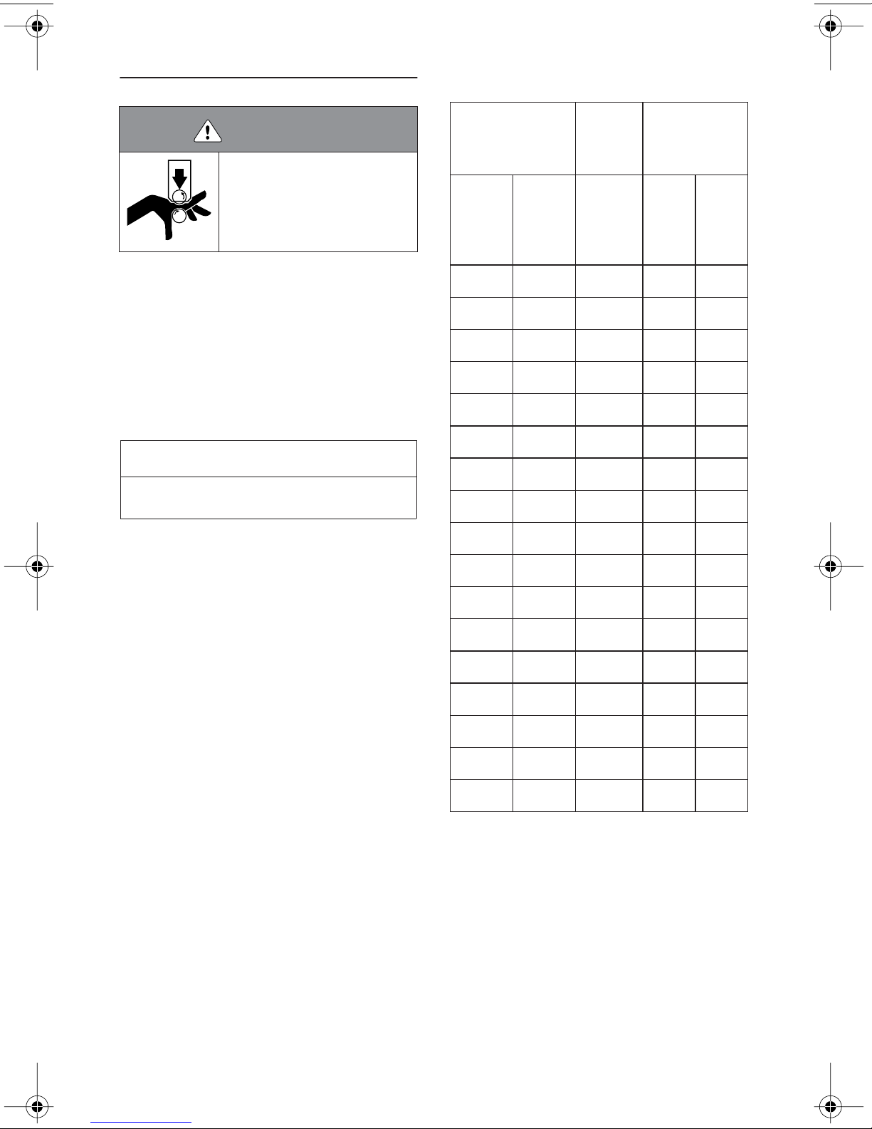
tool, and pipe stand by taking into consideration the following factors (refer to the drawing below for overall dimensions):
A
B
D
C
2c. A firm and level surface for the power
drive, tool, and pipe stand
2d. Adequate clearance around the tool for
adjustment and maintenance
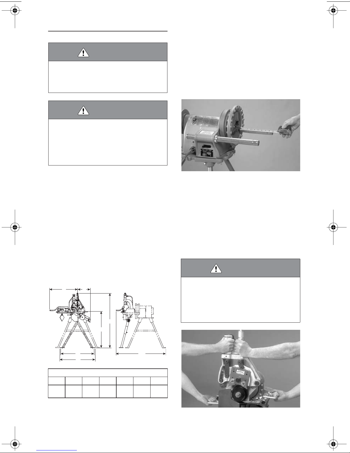
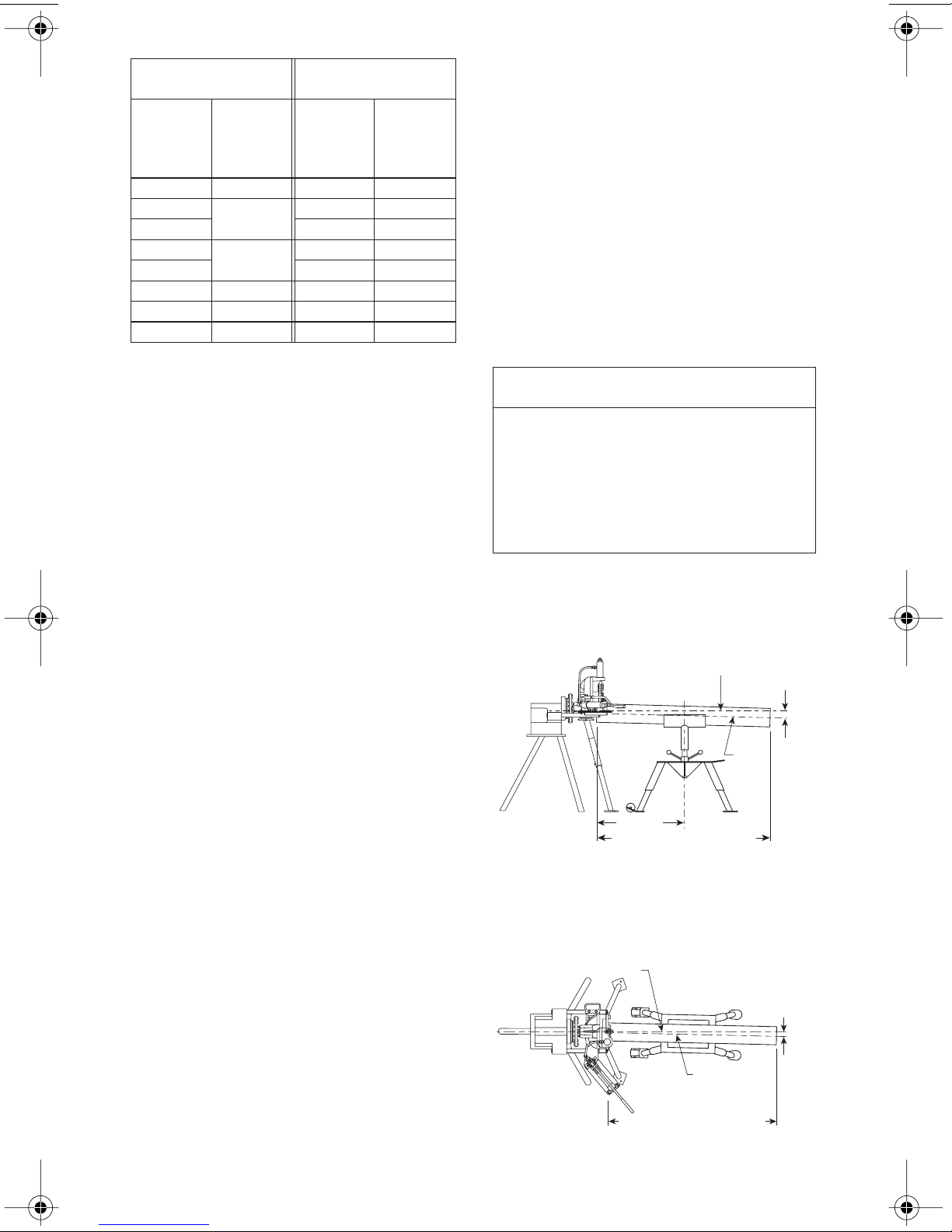
3. Remove threading dies, cutoff attachments, etc. from the power drive. Extend the
1
two tubular support arms approximately 7
/2
inches (190 mm) beyond the chuck of the
power drive. Secure the support arms in this
position. Refer to the power drive manufacturer’s instructions.
4. Open the chuck of the power drive fully.
Refer to the power drive manufacturer’s instructions.
WARNING
• Support of the tool head assembly must be maintained until the support legs are installed and
secured.
Failure to support the tool head assembly may cause
the tool to tip over, resulting in serious personal injury
and tool damage.
E* G**
F*
Dimensions – inches (millimeters)
ABCDEFG
28.00 15.00 37.00 56.25 34.25 27.50 61.00
(711) (381) (940) (1429) (870) (699) (1549)
NOTES:
*Mounting hole dimensions are approximate due to
variables when fastening legs.
**Dimension is approximate due to variables when
inserting into power drive.
VE272SFS Roll Grooving Tool 7
5. Slide the tool head assembly completely
onto the arms of the power drive.
Page 10
6. Allow approximately
1
/2-inch (13-mm)
clearance from the hex bolts on the back of
the tool to the power drive chuck.
7. Align the flat portions of the drive shaft
with the chuck jaws by turning the lower roll.
8. Tighten the chuck. Make sure the jaws
engage with the flats of the drive shaft.
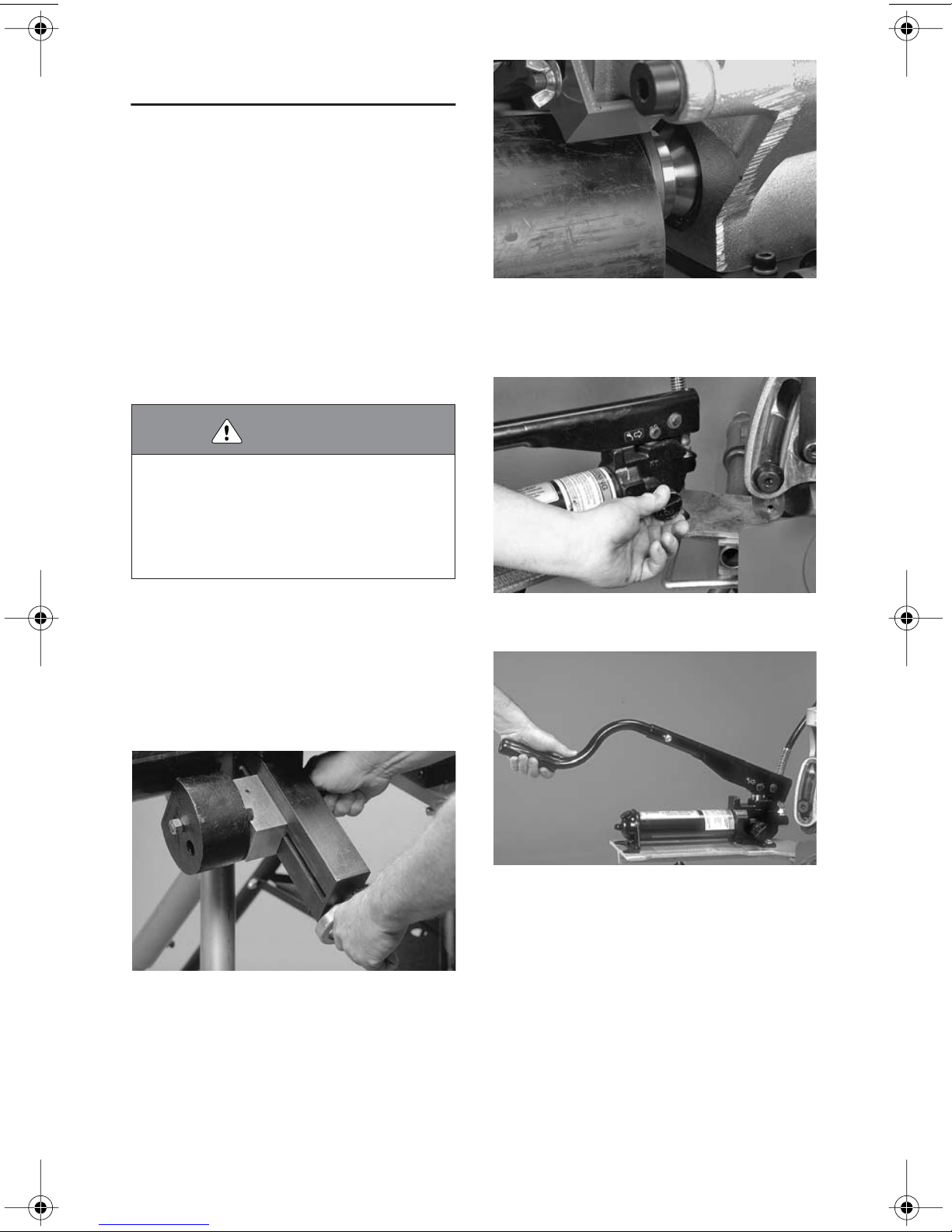
9. Insert the two adjustable legs completely
into the sockets of the upper leg. Hand-tighten the hex bolts.
11. Tighten the hex head bolt with a wrench.
12. Loosen the hex bolts to release the two
lower legs, allowing them to slide down to the
floor. Turn the leg pads at the bottom until they
are resting flat of the floor.
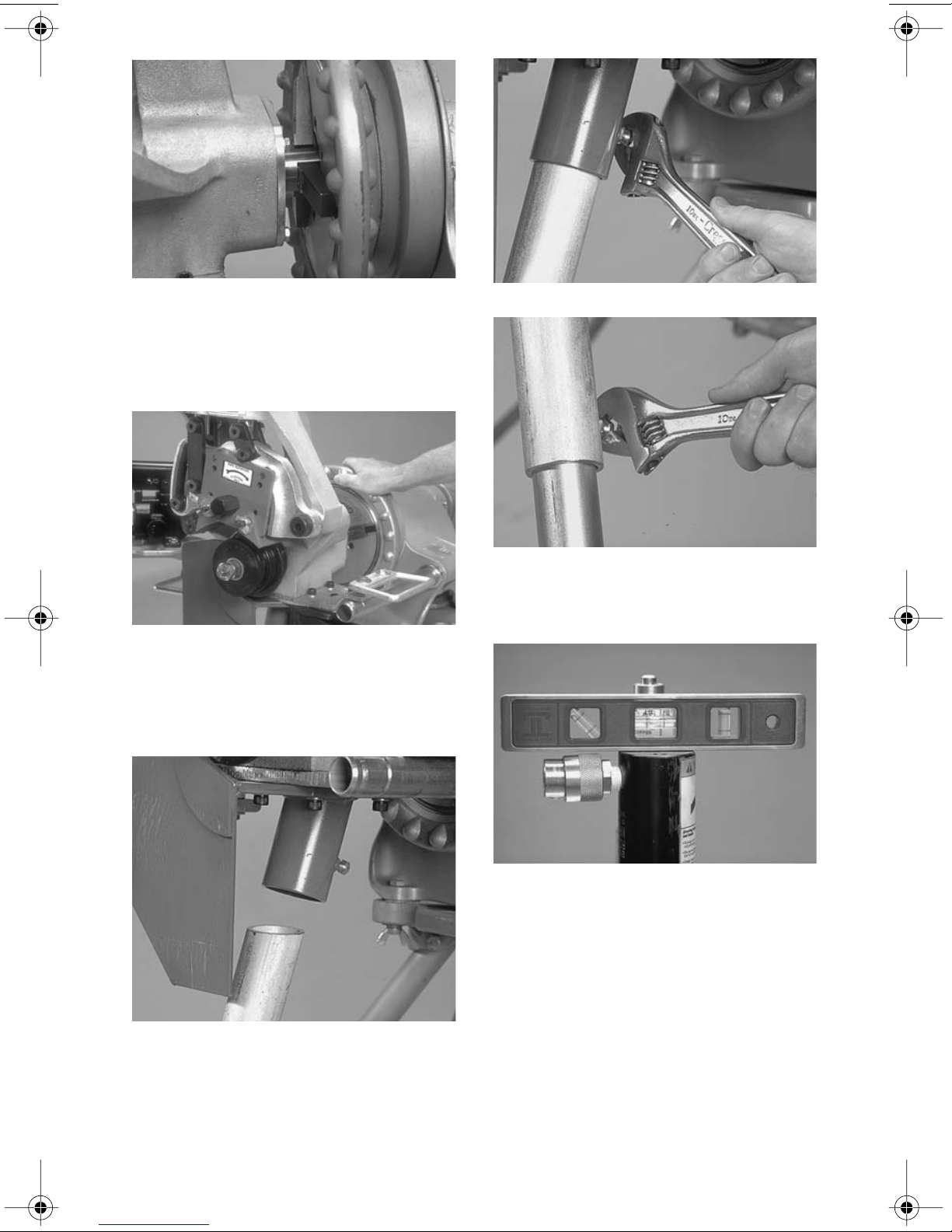
10. Insert the top of the leg assembly completely into the socket under the tool head
assembly. Rotate the assembly until it seats
completely in the socket. The hex head bolts
on the legs should be facing toward the back
of the machine (toward the power drive).
8 VE272SFS Roll Grooving Tool
13. Level the tool from front to back. NOTE:
The top of the hydraulic cylinder is a good location to measure “level,” as shown above.
Page 11
14. Using a wrench, tighten the two hex
head bolts on the two legs to maintain the
level position.
DANGER
• To reduce the risk of electric
shock, check the electrical
source for proper grounding and
follow all instructions.
• Before performing any maintenance on the tool, turn the
switch on the power drive to the
“OFF” position, or disconnect
the power cord from the electrical source.
Failure to follow these instructions could result in
death or serious personal injury.
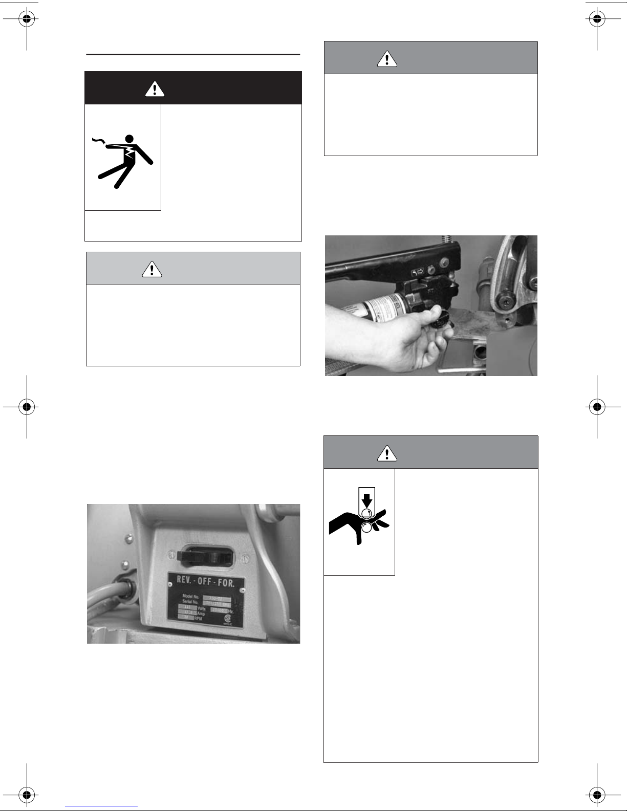
18. Make sure the switch on the power drive
is in the “OFF” position. Plug the power drive
into an internally grounded electrical outlet.
The outlet must meet the requirements for the
power drive (refer to the power drive manufacturer’s instructions). If an extension cord is
used, refer to the "Extension Cord Requirements" section on page 5 for requirements.
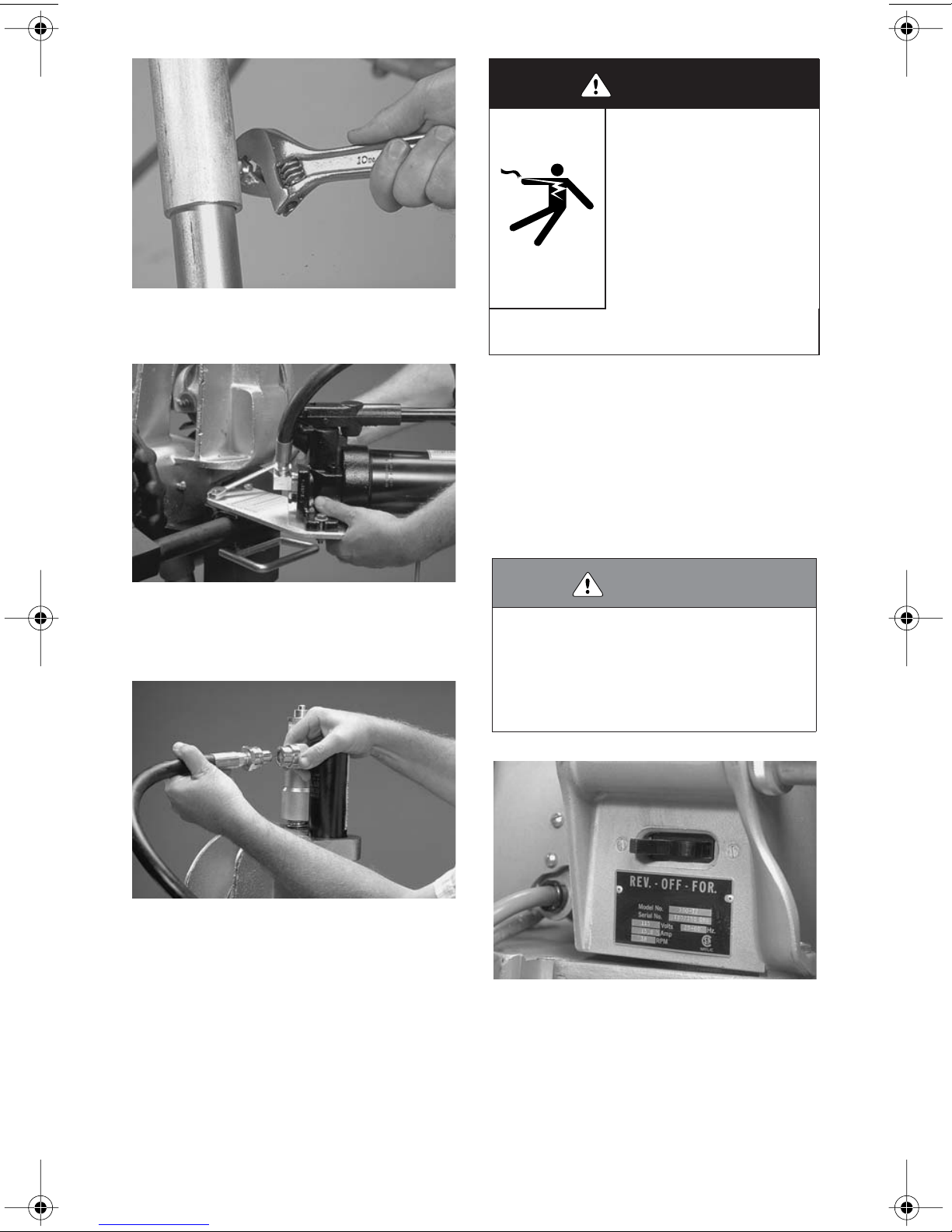
15. Attach the hand pump/pump support to
the left side of the tool with the two hex bolts
(supplied). Tighten the two hex bolts with a
wrench.
16. Connect the hydraulic line from the hand
pump to the power cylinder with the connectors provided.
17. Hang the guard setting pad on the hook
provided under the base of the hand pump.
WARNING
• The power drive MUST be operated with a safety
foot switch. If the power drive does not contain a
safety foot switch, contact the power drive manufacturer.
Operating the tool without a safety foot switch could
result in serious personal injury.
19. Turn the power drive switch to the position that will produce CLOCKWISE rotation of
the chuck when viewed from the front of the
tool. On the Victaulic VPD752 or Ridgid 300
Power Drive, placing the switch in the RE-
VERSE position will produce clockwise rotation of the chuck, lower roll, and pipe/tubing.
VE272SFS Roll Grooving Tool 9
Page 12
20. Depress the safety foot switch, check the
rotation of the chuck and lower roll, and make
sure the tool is stable. If rotation is counterclockwise, place the switch on the power
drive to the opposite position. If the tool wobbles, make sure the tool is mounted squarely
in the chuck and that the tool is level on the
floor. If the wobble persists, the power drive
support arms are bent or the power drive is
damaged. Have the power drive repaired if
the wobble persists.
21. Turn the switch on the power drive to the
“OFF” position, or disconnect the power cord
from the electrical source.
VE272SFS TOOL SETUP IS NOW
COMPLETE.
22. If the optional stabilizer assembly was
ordered separately, attach it to the right side
of the tool with the four hex bolts and four lock
washers provided.
22a. Use the hex bolts provided for installing
the screws.
10 VE272SFS Roll Grooving Tool
Page 13
PRE-OPERATION CHECKS AND
ADJUSTMENTS
Every Victaulic roll grooving tool is checked,
adjusted, and tested at the factory prior to
shipment. However, before attempting to
operate the tool, the following checks and
adjustments should be made to ensure
proper tool operation.
2. Raised internal and external weld beads
and seams must be ground flush with the
pipe/tubing surface 2 inches (50 mm) back
from the pipe/tubing ends.
3. All coarse scale, dirt, and other foreign
material must be removed from the interior
and exterior surfaces of the pipe/tubing ends.
CAUTION
WARNING
• Before making any tool adjustments, always turn
the switch on the power drive to the “OFF” position,
or disconnect the power cord from the electrical
source.
Accidental startup of the tool could result in serious
personal injury.
GROOVING ROLLS
Make sure the proper roll set is installed on
the tool for the pipe/tubing size and material
that will be grooved. Roll sets are marked with
the pipe/tubing size, part number, and they
are color coded for the pipe/tubing material.
Refer to the "Tool Rating and Roll Selection"
section, starting on page 39. If the proper rolls
are not installed on the tool, refer to the "Roll
Changing" section on page 23.
CAUTION
• For maximum grooving roll life, remove foreign
material and loose rust from the interior and exterior surfaces of the pipe/tubing ends. Rust is an
abrasive material that will wear the surface of
grooving rolls.
Foreign material may interfere with or damage grooving rolls, resulting in distorted grooves and grooves
that are out of Victaulic specifications.
GROOVABLE PIPE/TUBING
LENGTHS
The VE272SFS is capable of grooving short
pipe/tubing lengths without the use of a pipe
stand. Refer to the “Short Pipe/Tubing
Lengths” section on the following page.
Pipe/tubing lengths longer than those listed in
Table 1 on the following page (and up to 20
feet/6 meters) must be supported with a pipe
stand.
• Make sure roll-retaining bolts and nuts are tight.
Loose retaining bolts and nuts could cause damage to
the tool and rolls.
Pipe/tubing lengths from 20 feet (6 meters) up
to double-random lengths (approximately 40
feet/12 meters) must be supported with two
pipe stands.
PIPE/TUBING PREPARATION
For proper tool operation and production of
grooves that are within Victaulic specifications, the following guidelines must be followed.
1. Victaulic recommends square-cut pipe
for use with grooved-end pipe/tubing products. Square-cut pipe/tubing MUST be used
with FlushSeal
eled-end pipe/tubing may be used, provided
that the wall thickness is standard wall (ANSI
B36.10) or less and that the bevel meets ANSI
B16.25 (37
Roll grooving beveled-end pipe/tubing may
result in unacceptable pipe/tubing flare.
VE272SFS Roll Grooving Tool 11
®
and EndSeal® gaskets. Bev-
1
/2º) or ASTM A-53 (30°). NOTE:
Page 14
SHORT PIPE/TUBING LENGTHS
WARNING
Grooving rolls can crush or cut
fingers and hands.
• Never groove pipe/tubing that is
shorter than the recommended
lengths listed in this manual.
Table 1 shows the minimum and maximum
pipe/tubing lengths that can be grooved without the use of a pipe stand. Refer to the
"Grooving Operation" section, starting on
page 20, for instructions on how to groove
short pipe/tubing lengths. For pipe/tubing
longer than what is shown in Table 1, refer to
the "Long Pipe/Tubing Lengths" section on
page 13.
NOTICE
• Grooved pipe nipples, shorter than those listed in
Table 1, are available from Victaulic.
Table 1
TABLE 1 – GROOVABLE PIPE/TUBING
LENGTHS
CTS US
Steel, Stainless Steel,
Aluminum, and PVC
Pipe Size
Standard
Copper
Tubing Size
Length – inches
(mm)
Actual
Nominal
Pipe Size
inches or
mm
3
/
1
11/
11/
2
21/
3
31/
4
41/
5
152,4 mm
6
203,2 mm
8
10
12
4
4
2
2
2
2
Outside
Diameter
inches
(mm)
1.050
26,9 205 915
1.315
33,7 205 915
1.660
42,4 205 915
1.900
48,3 205 915
2.375
60,3 205 915
2.875
73,0 205 915
3.500
88,9 205 915
4.000
101,6 205 915
4.500
114,3 205 915
5.000
127,0 205 815
5.563
141,3 205 815
6.000
152,4 255 765
6.625
168,3 255 715
8.000
203,2 255 610
8.625
219,1 255 610
10.750
273,0 255 510
12.750
323,9 305 460
Nominal
Size
inches Minimum Maximum
–
–
–
–
2
1
/
2
2
3
–
4
–
5
–
6
–
8
–
–
836
836
836
836
836
836
836
836
836
832
832
10 30
10 28
10 24
10 24
10 20
12 18
12 VE272SFS Roll Grooving Tool
Page 15
Nominal Size
millimeters Length - millimeters
European
Standard
Copper
Tubing Size
54 DN50 205 915
64
66,7 205 915
76,1
88,9 205 915
108 DN100 205 915
133 DN125 205 815
159 DN150 255 715
Australian
Standard
Copper
Tubing Size Minimum Maximum
DN65
DN80
205 915
205 915
If pipe/tubing is required that is shorter than
the minimum length listed in Table 1, shorten
the next-to-last piece so that the last piece is
as long (or longer) than the minimum length
specified. Refer to the example below.
EXAMPLE: A 20-foot, 4-inch (6,2-m) length of
10-inch diameter steel pipe is required to finish a section, and only 20-foot (6,1-m) lengths
are available. Instead of roll grooving a 20foot (6,1-m) length of steel pipe and a 4-inch
(0,1-m) length of steel pipe, follow these
steps:
1. Refer to Table 1 on this and the previous
page, and note that for 10-inch diameter steel
pipe, the minimum length that should be roll
grooved is 10 inches (255 mm).
3. Installation of couplings on pipe/tubing
that exceeds the maximum allowable flare
may prevent pad-to-pad closure of the housings and/or may cause damage to the coupling gasket. Refer to the applicable “Roll
Groove Specifications” table for details.
4. If the tool is properly set up in a level
position, but the back end of the pipe/tubing
is higher than the end being grooved, the
pipe/tubing may not track. As a result, excessive flare may occur on the pipe/tubing end.
Refer to the "Tool Setup" section, starting on
page 7, and Figures 1 and 2 below for tool
setup and pipe positioning requirements.
NOTICE
• Figure 1 shows the Victaulic Adjustable Pipe Stand
(VAPS 112). The VAPS 112 is suitable for
inch sizes. The Victaulic Model VAPS 224 is suitable
for 2 – 24-inch sizes. Refer to the "Accessories"
section on page 35.
• For additional information about pipe stands, refer
to the instructions included with the pipe stand.
5. Place the pipe stand at a distance slightly beyond half the pipe/tubing length from the
tool. Refer to Figure 1 below.
Pipe angle
exaggerated for clarity
Centerline
Too l
(Level)
3
/
- 12-
4
¹⁄₂ to 1°
(2-4 inches/
51-102 mm)
2. Roll groove a 19-foot, 6-inch (5,9-m)
length of pipe and a 10-inch (255-mm) length
of pipe. Refer to the "Long Pipe/Tubing
Pipe
Centerline
Lengths" section on page 13.
10' +1' -0
LONG PIPE/TUBING LENGTHS
When roll grooving pipe/tubing that exceeds
Figure 1 - Support of Pipe
20-foot (6-meter) Length of Pipe
the maximum length shown in Table 1, a roller-type pipe stand must be used. The rollertype pipe stand must be capable of handling
the weight of the pipe/tubing, while allowing
the pipe/tubing to rotate freely.
1. Make sure the tool is level. Refer to the
"Tool Setup" section on page 7 for leveling
6. Position the pipe stand approximately
1
/2º to the left for the tracking angle. Refer to
Figure 2 below.
Tool Centerline
Pipe angle
exaggerated for clarity
0 to ¹⁄₂° Max.
(0-2 inches/
0-51 mm)
requirements.
2. When pipe/tubing flare is excessive,
Pipe Centerline
right-to-left tracking must be kept to a minimum. It may be necessary to use less than
1
/2º for the tracking angle.
20-foot (6-meter) Length of Pipe
Figure 2 - Tracking Angle
VE272SFS Roll Grooving Tool 13
Page 16
ROLL GUARD ADJUSTMENT
WARNING
• Before making any tool adjustments, always turn
the switch on the power drive to the “OFF” position,
or disconnect the power cord from the electrical
source.
Accidental startup of the tool could result in serious
personal injury.
VE272SFS guards must be adjusted every
time rolls are changed or when the pipe/tubing size or wall thickness is different from
pipe/tubing that was grooved previously.
1. Make sure the proper roll set is installed
on the tool for the pipe/tubing size and material that will be grooved. Roll sets are marked
with the pipe/tubing size/part number, and
they are color-coded for the pipe material. Refer to the "Tool Rating and Roll Selection" section, starting on page 39. If the proper rolls are
not installed on the tool, refer to the "Roll
Changing" section on page 23.
be grooved. To set the groove diameter stop,
back off the depth adjuster lock, align the
depth adjuster with the proper diameter and
thickness, and lock the setting in position with
the depth adjuster lock.
4. If the tool is equipped with a stabilizer,
retract the stabilizer, if necessary, to insert the
pipe. To retract the stabilizer, loosen the stablizer locking handle, and retract the stabilizer roller with the hand wheel to provide
clearance for the pipe when it is inserted onto
the lower roll.
WARNING
2. Loosen the wing nuts, and move the roll
guards to the full-up position. Tighten the
wing nuts.
3. Set the groove diameter stop to the pipe/
tubing size and schedule/thickness that will
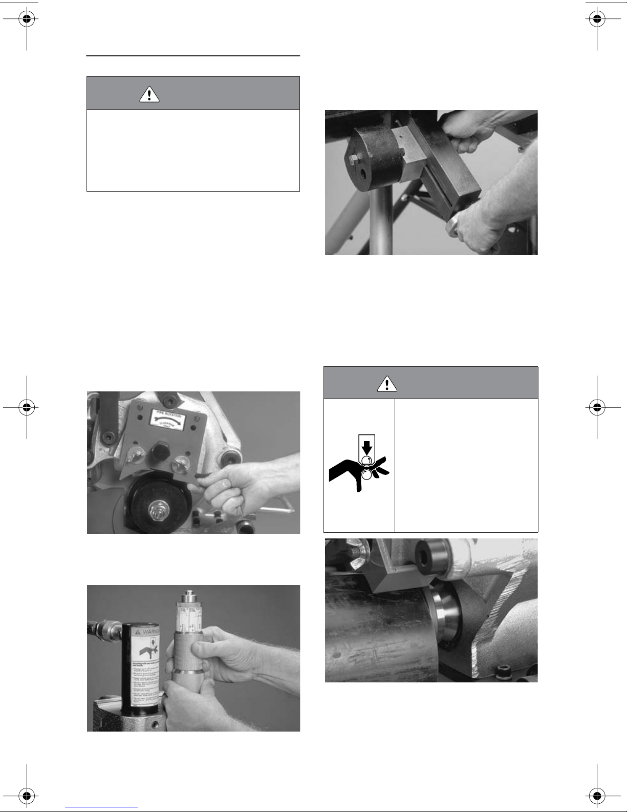
Grooving rolls can crush or cut
fingers and hands.
• Loading and unloading pipe/tubing will place your hands close to
the rollers. Make sure your hands
are away from the rollers when
the machine is running.
• Never groove pipe/tubing that is
shorter than the recommended
lengths listed in this manual.
5. Insert a length of pipe/tubing of the correct size and schedule/ thickness over the
lower roll with the pipe/tubing end against the
lower roll backstop flange. Refer to the "Pipe/
Tubing Preparation" section on page 11.
14 VE272SFS Roll Grooving Tool
Page 17

6. Close the hand pump valve by turning
the knob clockwise.
7. Using the hand pump, bring the upper
roll down into firm contact with the pipe/tubing.
9. Loosen the wing nuts, and adjust each
guard to conform to and lightly pinch the
guard-setting pad against the pipe/tubing.
Tighten the wing nuts to secure the guards
into position.
10. Remove the guard-setting pad. Store the
pad back on the hook provided under the
pump support.
8. Remove the guard-setting pad from its
storage hook beneath the pump support.
Hold the guard-setting pad firmly against the
pipe/tubing, and push it under the roll guards
until it is flush against the red plate.
VE272SFS Roll Grooving Tool 15
Page 18
PIPE STABLIZER
ADJUSTMENT
(Applies only to tools equipped with the
optional pipe stabilizer)
The optional pipe stabilizer for the VE272SFS
is designed to prevent pipe sway for 8 –
12-inch NPS sizes in short and long lengths.
When the stabilizer is adjusted for a selected
pipe size and wall thickness, it does not require further adjustment unless pipe of a different size and wall thickness will be grooved.
Pipe of the same size and thickness may be
moved in and out of the tool without retracting
the stabilizer.
WARNING
• Before making any tool adjustments, always turn
the switch on the power drive to the “OFF” position,
or disconnect the power cord from the electrical
source.
Accidental startup of the tool could result in serious
personal injury.
3. Insert a length of pipe that is the correct
size and schedule over the lower roll. Make
sure the pipe end contacts the lower-roll
backstop flange.
1. Make sure the proper roll set is installed
on the tool for the pipe size and material to be
grooved. Rolls are marked with the pipe size,
part number, and they are color-coded according to the pipe material. Refer to the "Tool
Rating and Roll Selection" section, starting on
page 39.
2. Loosen the stabilizer locking handle. Using the hand wheel, retract the stabilizer roller
to clear the pipe when it is inserted onto the
lower roll.
4. Close the hand pump valve by turning
the knob clockwise.
5. Using the hand pump, bring the upper
roll down into firm contact with the pipe.
6. Make sure the guards are adjusted properly. Refer to the "Roll Guard Adjustment" section on page 14.
16 VE272SFS Roll Grooving Tool
Page 19

CAUTION
• DO NOT adjust the stabilizer to push the pipe to the
left and off center from the rolls. Increased pipe-end
flare and shortened roll life will result if the pipe is
pushed to the left and off center.
• Assembly of couplings on pipe that exceeds the
maximum allowable flare dimension may prevent
proper pad-to-pad assembly of coupling housings
and may cause gasket distortion/damage.
Failure to prepare pipe in accordance with all instructions may cause joint failure, resulting in personal
injury and/or property damage.
Figure 3 - “CORRECT”
7. Using the hand wheel, advance the stabilizer roller inward until the roller lightly contacts the pipe. Tighten the stablizer locking
handle. Refer to Figures 3 and 4 on this page
for proper positioning.
8. Complete all adjustments and groove
the pipe. Refer to the "Grooving Operation"
section, starting on page 20. Observe the
stabilizer roller while grooving. It should
remain in contact with the pipe, and the pipe
should rotate smoothly without swaying from
side to side. If the pipe is not rotating smoothly
or is swaying from side to side, adjust the stabilizer roller further inward. Continue the
grooving operation and make further adjustments, as necessary. DO NOT adjust the stabilizer too far inward, since it will skew the
pipe to the left and off center, resulting in excessive pipe-end flare.
Figure 4 - “INCORRECT”
VE272SFS Roll Grooving Tool 17
Page 20

GROOVE DIAMETER STOP
ADJUSTMENT
The groove diameter stop must be adjusted
for each pipe/tubing size or change in wall
thickness. The groove diameter, which is
identified as the “C” dimension,” is listed under the "Roll Groove Specifications" section,
starting on page 45. In addition, a label is affixed to the tool, which lists the “C” dimensions.
NOTICE
• To perform the following adjustments, use several
short, scrap sections of pipe/tubing that are the
proper material, diameter, and thickness to be
grooved. Make sure the scrap sections meet the
length requirements listed in Table 1 on page 12.
To achieve the proper diameter:
a. Determine the diameter and thickness of
the pipe/tubing to be grooved.
b. Locate the proper pipe diameter and
thickness on the pipe/tubing-size indicator
label of the depth stop. The depth stop can be
rotated for easy viewing.
2. Insert a length of pipe/tubing over the
lower roll with the pipe/tubing end against the
lower-roll backstop flange.
WARNING
Grooving rolls can crush or cut
fingers and hands.
• Before making any tool adjustments, always turn the switch on
the power drive to the “OFF”
position, or disconnect the
power cord from the electrical
source.
• Make sure the guard is adjusted properly before
grooving pipe/tubing.
• Loading and unloading pipe/tubing will place your
hands close to the rollers. Keep hands away from
the grooving rolls and stabilizer wheel during operation.
• Never reach inside pipe/tubing end or across the
tool or pipe/tubing during operation.
• Always groove pipe/tubing in a CLOCKWISE direction only.
• Never groove pipe/tubing that is shorter than the
recommended lengths listed in this manual.
• Never wear loose clothing, loose gloves, or anything
that can become entangled in moving parts
1. Back off the depth adjuster lock. Align
the top edge of the depth adjuster with the line
down and to the right of the proper size and
schedule markings, as shown above. Lock
the depth adjuster in position with the depth
adjuster lock.
NOTICE
• The markings provide an approximate groove diameter adjustment and are not exact groove diameter
settings. Variations in pipe/tubing OD and wall
thickness make it impossible to calibrate the groove
diameter stop exactly.
18 VE272SFS Roll Grooving Tool
3. Prepare a trial groove. Refer to the
"Grooving Operation" section, starting on
page 20.
Page 21

4. After a trial groove is prepared and the
pipe/tubing is removed from the tool, carefully
check the groove diameter (“C” dimension).
Refer to the "Roll Groove Specifications" section, starting on page 45. The PT-100 Pipe
Tape, supplied with the tool, is the best method for checking the “C” dimension. In addition, a vernier caliper or narrow-land
micrometer can be used to check this dimension at two locations (90º apart) around the
groove. The average reading must be within
the required groove diameter specification.
6. Prepare another trial groove, and check
the groove diameter (“C” dimension), as
described in step 4. Repeat these steps, as
necessary, until the groove diameter is within
specification.
CAUTION
• The “C” dimension (groove diameter) must conform
to Victaulic specifications to ensure proper joint
performance.
Failure to follow this instruction could cause joint
failure, resulting in personal injury and/or property
damage.
5. If the groove diameter (“C” dimension) is
not within Victaulic specifications, the diameter stop must be adjusted.
5a. To adjust for a smaller groove diameter,
turn the depth adjuster counterclockwise
(when viewed from above the tool).
5b. To adjust for a larger groove diameter,
turn the depth adjuster clockwise (when
viewed from above the tool).
NOTE: A quarter-turn either way will change
the groove diameter adjustment by approximately 0.031 inch (0,8 mm) or 0.125 inch (3,2
mm) per full turn.
VE272SFS Roll Grooving Tool 19
Page 22
GROOVING OPERATION
DANGER
• To reduce the risk of electric
shock, check the electrical
source for proper grounding and
follow all instructions.
• Before operating the tool, review
the "Operator Safety Instructions" section on page 3 of this
manual.
Failure to follow these instructions could result in
death or serious personal injury.
CAUTION
• This tool must be used ONLY for roll grooving pipe/
tubing designated in the “Tool Rating and Roll
Selection” section of this manual.
Failure to follow this instruction could overload the
tool, resulting in reduced tool life and/or damage to
the tool.
WARNING
• The power drive MUST be operated with a safety
foot switch. If the power drive does not contain a
safety foot switch, contact the power drive manufacturer.
Operating the tool without a safety foot switch could
result in serious personal injury.
4. Make sure the tool is operational by
depressing the safety foot-switch pedal. The
lower roll must turn CLOCKWISE when
viewed from the front of the tool. Remove foot
from the safety foot switch.
1. Before grooving, make sure all instructions in the previous sections of this manual
have been followed.
2. Plug the power drive into an internally
grounded electrical source. NOTE: The power drive MUST be grounded. Refer to the power drive manufacturer’s instructions for
detailed information.
3. Set the power drive switch to produce
CLOCKWISE rotation of the lower roll and
pipe/tubing when viewed from the front of the
tool. On the Victaulic VPD752 Power Drive
and Ridgid 300 Power Drive, place the switch
in the reverse position to produce clockwise
rotation of the lower roll and pipe/tubing.
5. Open the hand pump valve by turning
the knob counterclockwise. Opening the
hand pump valve will allow the upper roll and
arm to move to the full up position.
WARNING
Grooving rolls can crush or cut
fingers and hands.
• Before making any tool adjustments, always turn the switch on
the power drive to the “OFF”
position, or disconnect the
power cord from the electrical
source.
• Make sure the roll guards are adjusted properly
before grooving pipe/tubing.
• Loading and unloading pipe/tubing will place your
hands close to the rollers. Keep hands away from
the grooving rolls and stabilizer wheel during operation.
• Never reach inside pipe/tubing end or across the
pipe/tubing during operation.
• Always groove pipe/tubing in a CLOCKWISE direction only.
• Never groove pipe/tubing that is shorter than the
recommended lengths listed in this manual.
• Never wear loose clothing, loose gloves, or anything
else than can become entangled in moving parts
20 VE272SFS Roll Grooving Tool
Page 23

6. Insert a length of pipe/tubing that is the
correct size and thickness onto the lower roll.
Make sure the pipe/tubing end contacts the
lower-roll backstop flange completely. If the
pipe/tubing is being supported with a pipe
stand, remove hands from the pipe/tubing.
7. Close the hand pump valve by turning
the knob clockwise.
9. Depress and hold down the safety footswitch pedal. The pipe/tubing will begin to rotate clockwise. As the pipe/tubing rotates, begin the grooving process by slowly pumping
the handle of the hand pump.
NOTICE
• DO NOT pump the handle too fast. The rate should
be sufficient to groove the pipe/tubing and maintain
an audible, moderate-to-heavy load on the power
drive motor.
8. Use the hand pump to bring the upper
roll down into firm contact with the pipe/tubing.
8a. If grooving a short length of pipe/tubing
(refer to Table 1 on page 12 for requirements), remove hands from the pipe/tubing.
VE272SFS Roll Grooving Tool 21
10. Continue the grooving process until the
depth stop makes firm contact with the top of
the tool body. Continue to rotate the pipe/tubing for one to three revolutions to ensure
groove completion.
11. Release the safety foot switch pedal, and
withdraw foot from the safety foot switch.
WARNING
• DO NOT place hands inside the pipe/tubing end or
in the area of the grooving rolls or stabilizer roller
while the pipe/tubing is still rotating.
Failure to follow these instructions could result in
serious personal injury.
Page 24

11a. If a short length of pipe/tubing is in the
tool, manually support the pipe/tubing.
12. To release the pipe/tubing, open the
hand pump valve by turning the knob coun-
terclockwise. Remove the pipe/tubing from
the tool.
NOTICE
• The groove diameter must be within specification
for the diameter and wall thickness of pipe/tubing.
The groove diameter should be checked and
adjusted, as necessary, to ensure grooves remain
within specification.
22 VE272SFS Roll Grooving Tool
Page 25

ROLL CHANGING
WARNING
• Before changing rolls, always turn the switch on the
power drive to the “OFF” position, or disconnect the
power cord from the electrical source.
Accidental startup of the tool could result in serious
personal injury.
The VE272SFS roll grooving tool is designed
with rolls to accommodate several pipe/tubing sizes, which eliminates the need for frequent roll changes.
An upper roll and a “Keyless” lower roll for 8 –
12-inch steel pipe are factory installed on the
tool. When 2 – 6-inch steel pipe or other pipe
materials are required for grooving, the upper
and lower rolls must be changed. Refer to the
following sections:
1. "Upper Roll Removal" section on
page 25
5. "Upper Roll Installation" section on
page 28
In addition, different pipe materials may require different rolls. For proper roll selection,
refer to the "Tool Rating and Roll Selection"
section, starting on page 39.
2. "Lower Roll Removal for 2-inch and
Larger Sizes" section on page 24
3. "Lower Roll Installation for 2-inch and
Larger Sizes" section on page 30
4. "Upper Roll Installation" section on
page 28
1
When 1
/2-inch and smaller size steel pipe is
required for grooving, the optional lower roll/
adapter assembly for 3/4-inch and 1 – 11/2-inch
steel pipe must be ordered and installed. In
addition, the correct upper roll for steel pipe
must be installed. To accomplish this, the upper and lower rolls and the arbor for 2-inch
and larger sizes must be removed. Refer to
the following sections:
1. "Upper Roll Removal" section on
page 25
2. "Lower Roll Removal for 2-inch and
Larger Sizes" section on page 24
3. "Arbor Removal" section on page 26
4. "Lower Roll/Adapter Assembly Installa-
tion" section on page 27
VE272SFS Roll Grooving Tool 23
Page 26
LOWER ROLL REMOVAL
for 2-inch and Larger Sizes
1. Open the hand pump valve by turning
the knob counterclockwise. Opening the
hand pump valve will allow the upper roll and
arm to move to the full up position.
WARNING
DO NOT strike the roll with a hammer or other blunt object. Striking
the roll can cause fragmentation,
resulting in serious personal injury.
• Always wear safety glasses.
• Use only the supplied aluminum wedge for roll
removal.
• Use only soft-faced hammers with the aluminum
wedge.
• Never strike the roll directly for any reason.
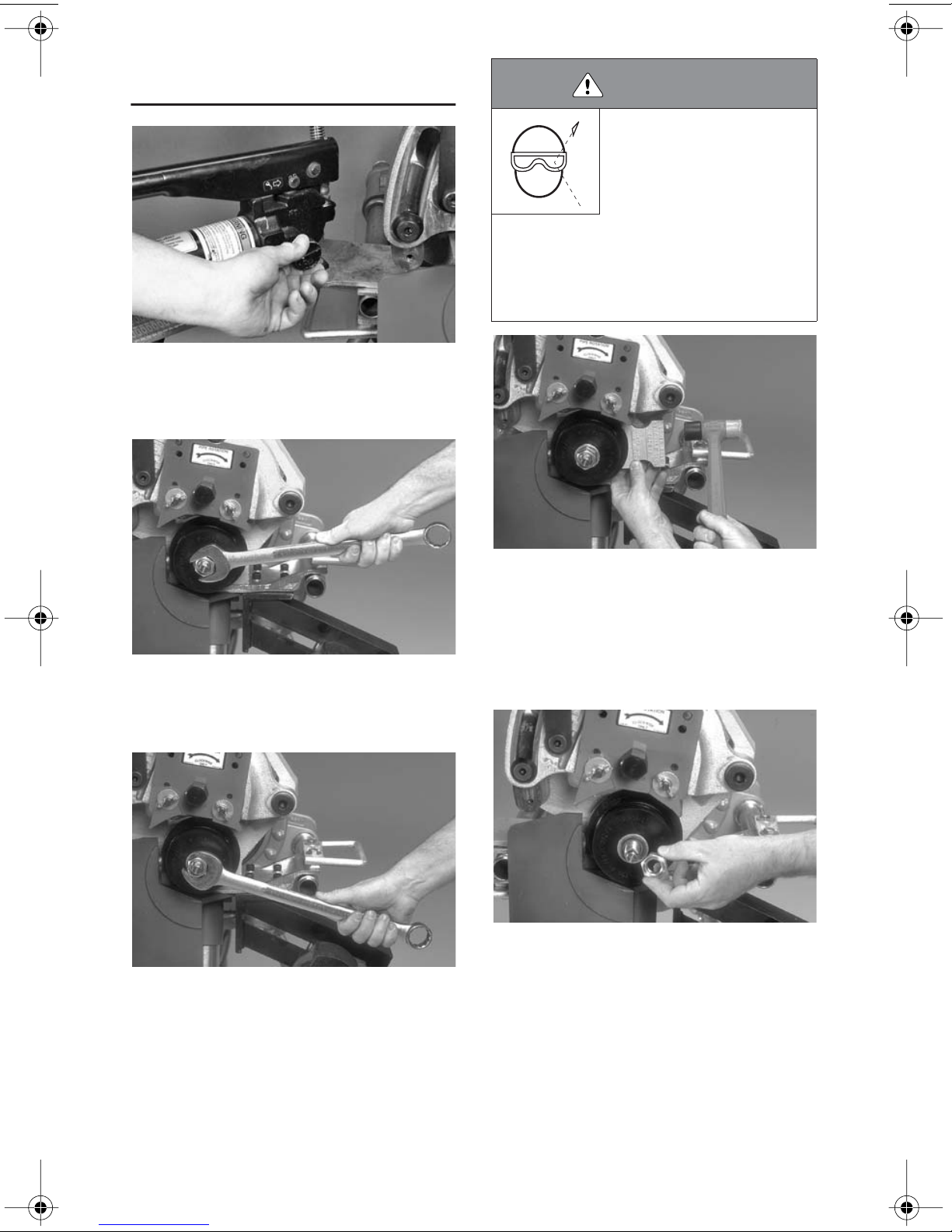
2. Using a wrench, loosen (counterclock-
wise) and remove the thin jam nut that
secures the thicker nut onto the threaded stud
of the arbor.
3. Using a wrench, loosen (counterclock-
wise) the thicker nut on the threaded stud of
the arbor. Back off the nut approximately 1/4
inch (6 mm) without removing it from the
threaded stud of the arbor.
4. To loosen the lower roll from the arbor,
use the aluminum wedge supplied with the
tool. Place the aluminum wedge behind the
lower roll, and strike the wedge with a softfaced hammer to break the roll loose from the
arbor. DO NOT STRIKE THE ROLL DIRECT-
LY WITH A HAMMER.
5. Remove the thick nut, washer, and lower
roll. Store these items in a clean, dry location.
24 VE272SFS Roll Grooving Tool
Page 27
UPPER ROLL REMOVAL
1. Using a wrench, loosen (counterclock-
wise) and remove the bolt from the upper roll.
Store the bolt in a clean, dry location.
2. Remove the upper roll assembly. Store
the upper roll in a clean, dry location.
VE272SFS Roll Grooving Tool 25
Page 28

ARBOR REMOVAL
This procedure is necessary for grooving
smaller-size pipe or for replacing a damaged
arbor. The standard arbor installed in the tool
is specifically for 2 – 12-inch pipe. When it is
necessary to groove 1
1
/2-inch and smaller
size pipe, the optional lower roll/adapter assembly must be ordered and installed.
1. Refer to the "Lower Roll Removal for 2inch and Larger Sizes" section, starting on
page 24, to remove the lower roll.
CAUTION
• NEVER operate the tool with jack bolts installed in
the arbor.
Failure to follow this instruction will result in improper
tool operation and tool damage.
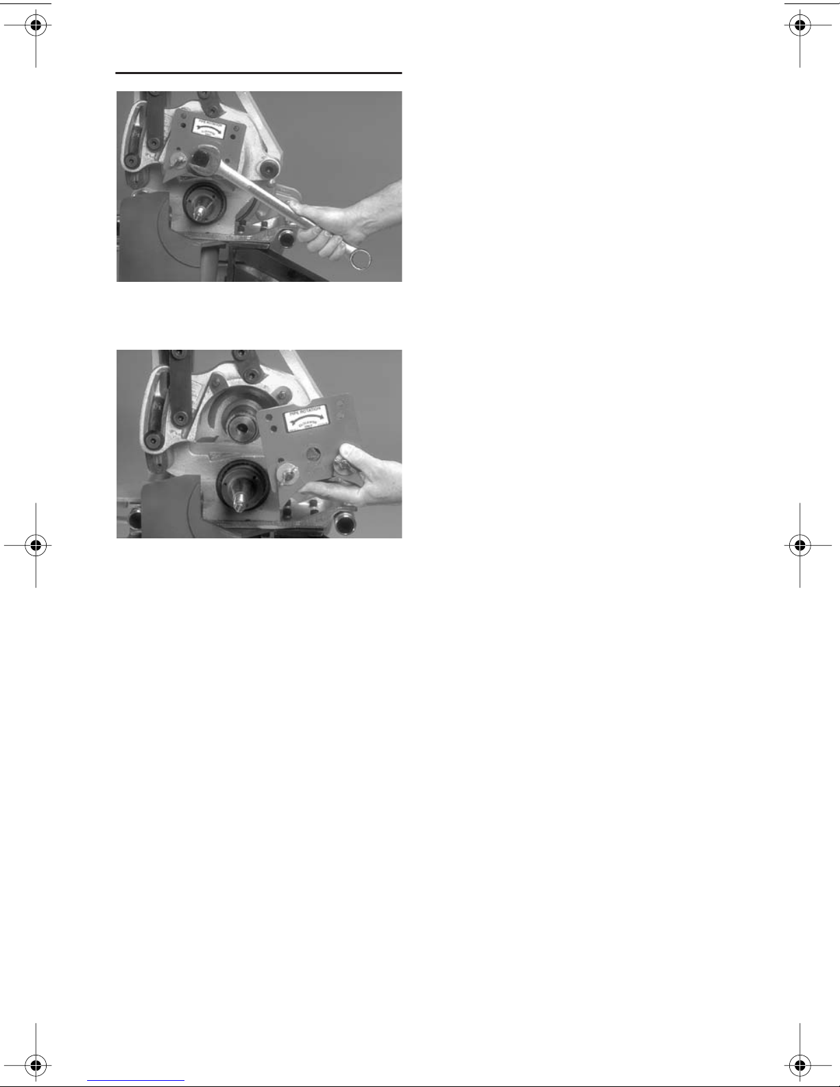
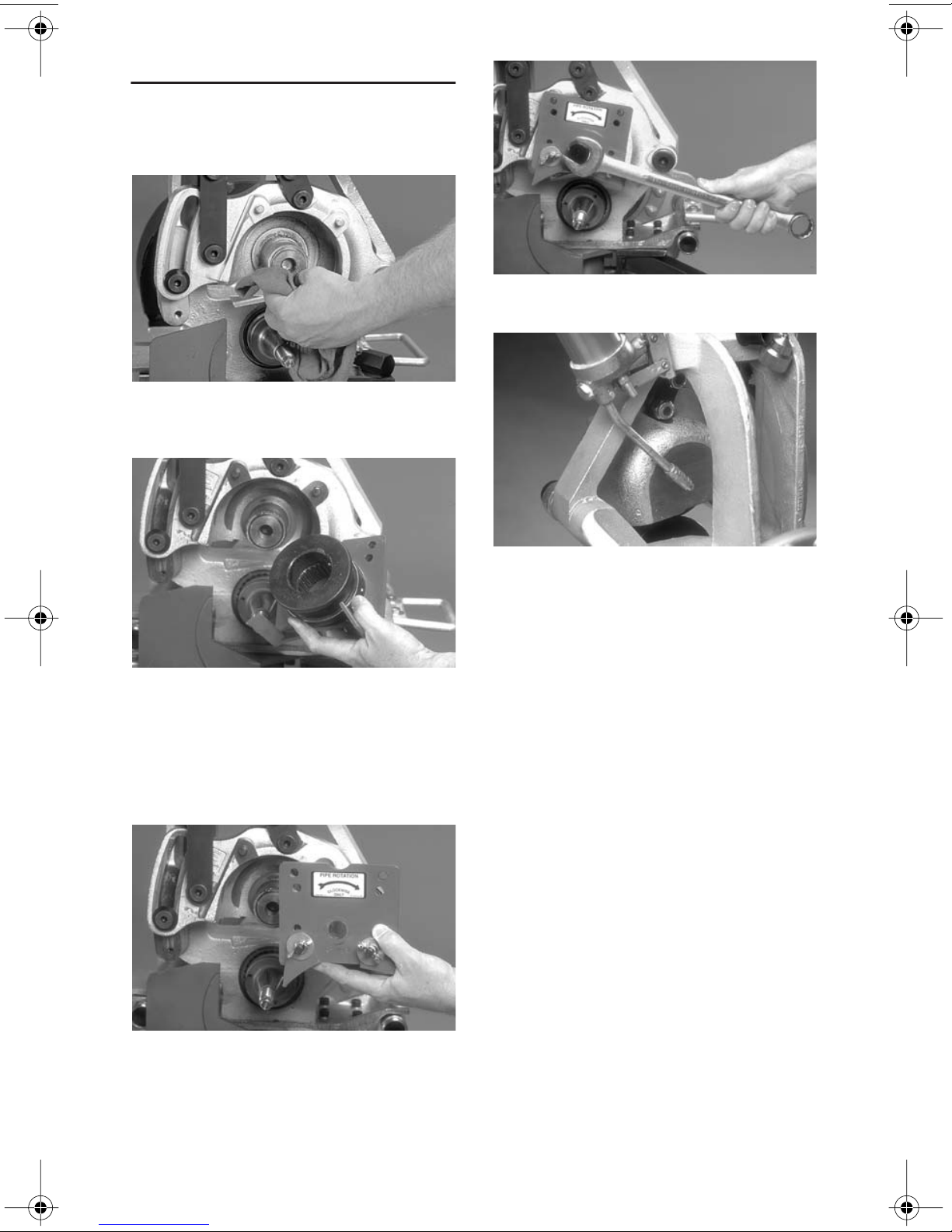
2. With a wrench engaged on the exposed
hex-portion stud of the arbor, loosen the arbor
by turning counterclockwise. NOTE: The
arbor should move outward as it is being loosened.
3. When the arbor has stopped moving outward, pull the arbor out of the tool. Store the
arbor in a clean, dry location.
NOTICE
• If the arbor was insufficiently lubricated, it may be
difficult to remove it from the drive shaft.
1
• The arbor features three
so that jack bolts (not supplied) can be used to
push the arbor out of the tool.
/4 - 20 UNC tapped holes
26 VE272SFS Roll Grooving Tool
Page 29
LOWER ROLL/ADAPTER
ASSEMBLY INSTALLATION
for 3/4-inch and 1 – 11/2-inch Sizes
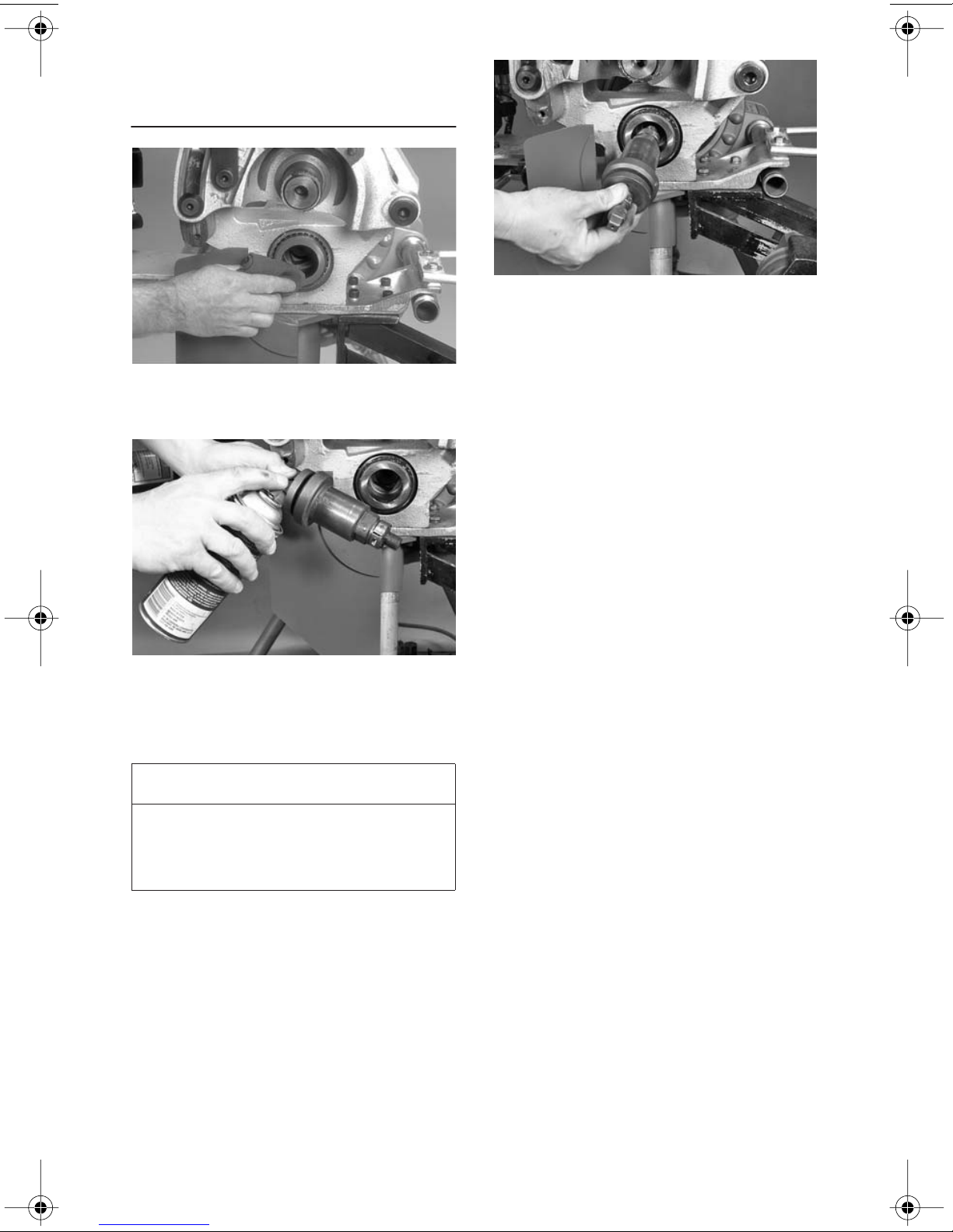
1. Using a soft cloth, clean the bore of the
main shaft and the lower roll/adapter assembly.
3. Carefully insert the lower roll/adapter
assembly into the main shaft. Make sure the
lower roll/adapter assembly is fully seated on
the main shaft. It may be necessary to rotate
the lower roll/adapter assembly to align its
square end with the square bore in the main
shaft. Tighten the lower roll/adapter assembly
by turning counterclockwise.
2. Lightly lubricate the lower roll/adapter
assembly with dry graphite spray (supplied
with the tool and available from the Victaulic
Tool Company).
NOTICE
• The 3/4-inch and 1 – 11/2-inch lower roll/adapter
assembly is held in position with left-hand threads
and must be tightened by turning COUNTERCLOCKWISE.
Lower Roll/Adapter Assembly Installation
VE272SFS Roll Grooving Tool 27
Page 30
UPPER ROLL INSTALLATION
Refer to the "Tool Rating and Roll Selection"
section, starting on page 39, for information
regarding grooving rolls.
1. Before installing the upper roll, clean any
dirt and scale from all shaft surfaces and roll
bores.
4. Insert the bolt for the upper roll. Tighten
the bolt (clockwise) securely with a wrench.
2. While the upper roll is removed from the
tool, inspect the internal roller bearing for contamination, proper lubrication, and freedom of
movement. In addition, inspect the guards for
wear and freedom of movement. Repair or
replace damaged components, as necessary.
5. Lubricate the upper roll bearing. Refer to
the "Maintenance" section, starting on
page 32, for additional maintenance information.
3. Carefully slide the desired upper roll assembly onto the upper shaft with the red plate
facing out. Loosen the guards, if necessary,
to ease installation. Make sure the red plate
engages the two pins on the arm and that it
contacts the front of the upper roll shaft.
28 VE272SFS Roll Grooving Tool
Page 31
LOWER ROLL/ADAPTER
ASSEMBLY REMOVAL
for 3/4-inch and 1 – 11/2-inch Sizes
1. Open the hand pump valve by turning
the knob counterclockwise. Opening the
hand pump valve will allow the upper roll and
arm to move to the full up position.
NOTICE
ARBOR INSTALLATION
1. Using a soft cloth, clean the bore of the
main shaft and the arbor.
• The 3/4-inch and 1 – 11/2-inch lower roll/adapter
assembly is held in position with left-hand threads
and must be removed by turning CLOCKWISE.
2. With a wrench engaged on the square
end of the lower roll/adapter assembly, remove the lower roll/adapter assembly by turning clockwise. Store the lower roll/adapter
assembly in a clean, dry location.
2. Lightly lubricate the arbor with dry
graphite spray (supplied with the tool and
available from the Victaulic Tool Company).
3. Carefully insert the arbor into the main
shaft. Make sure the arbor is fully seated in the
main shaft. It may be necessary to rotate the
arbor to align its square end with the square
bore in the main shaft. Tighten the arbor into
the main shaft by turning the exposed hexportion of the threaded stud clockwise.
VE272SFS Roll Grooving Tool 29
4. Install the lower roll for the correct size
and pipe material by referring to the "Lower
Roll Installation" section on page 30.
4a. Make sure the upper roll is installed for
the correct pipe size and material.
Page 32

LOWER ROLL INSTALLATION
for 2-inch and Larger Sizes
Lower Roll Installation
NOTICE
• The arbor must be installed before attempting to
install the lower roll. Refer to the "Arbor Installation" section on page 29.
CAUTION
• Make sure the square drive flats of the roll are
aligned properly with the square drive flats of the
arbor.
• Make sure the thick nut is tightened securely onto
the threaded stud of the arbor.
Failure to follow these instructions can result in the
lower roll slipping on the arbor and causing damage to
the arbor.
1. Place the lower roll onto the arbor. Reposition the roll guards, if necessary, to ease
assembly. Make sure the lower roll fits fully
onto the arbor. NOTE: The square drive flats
of the roll must be aligned with the square
drive flats of the arbor.
3. Install the thin jam nut onto the threaded
stud of the arbor. Using a wrench, tighten the
thin jam nut clockwise securely against the
thick nut.
4. Close the hand pump valve by turning
the knob clockwise.
2. Install the flat washer and thick nut onto
the threaded stud of the arbor in front of the
lower roll. Tighten the thick nut clockwise
securely with a wrench.
30 VE272SFS Roll Grooving Tool
5. Pump the hand pump several times until
the upper roll interlocks with the lower roll.
This will confirm proper roll installation.
Page 33

6. Open the hand pump valve by turning
the knob counterclockwise.
7. Lower roll installation for 2-inch and larger sizes is now complete. Before grooving,
follow all steps in the "Pre-Operation Checks
and Adjustments" section on page 11.
VE272SFS Roll Grooving Tool 31
Page 34

MAINTENANCE
DANGER
• Before performing any maintenance on the tool, turn the
switch on the power drive to the
“OFF” position, or disconnect
the power cord from the
electrical source.
Failure to follow these instructions could result in
death or serious personal injury.
This section provides information about keeping tools in proper operating condition and
guidance for making repairs, when necessary. Preventive maintenance during operation will pay for itself in repair and operating
savings.
Replacement parts must be ordered from
Victaulic Tool Company to ensure proper and
safe operation of the tool.
3. Grease the main shaft bearings at the
grease fitting with a No. 2EP lithium-base
grease, as shown above.
LUBRICATION
1. After every 8 hours of operation, lubri-
cate the machine. Always lubricate the upper
roll bearings when rolls are changed.
2. Grease the upper roll bearing at the
grease fitting with a No. 2EP lithium-base
grease, as shown above.
4. Lubricate the linkage mechanisms, the
arm pivot point, and the arm sliding surfaces
with a heavy-duty spray lubricant, or grease
may be applied by hand.
5. For tools equipped with the optional
pipe stabilizer: Lubricate the stabilizer wheel
with a No. 2EP lithium-base grease, as shown
above.
32 VE272SFS Roll Grooving Tool
Page 35

CHECKING AND FILLING
HYDRAULIC SYSTEMS
The hydraulic fluid level in the hand pump
must be checked semi-annually or if the
pump feels “spongy.”
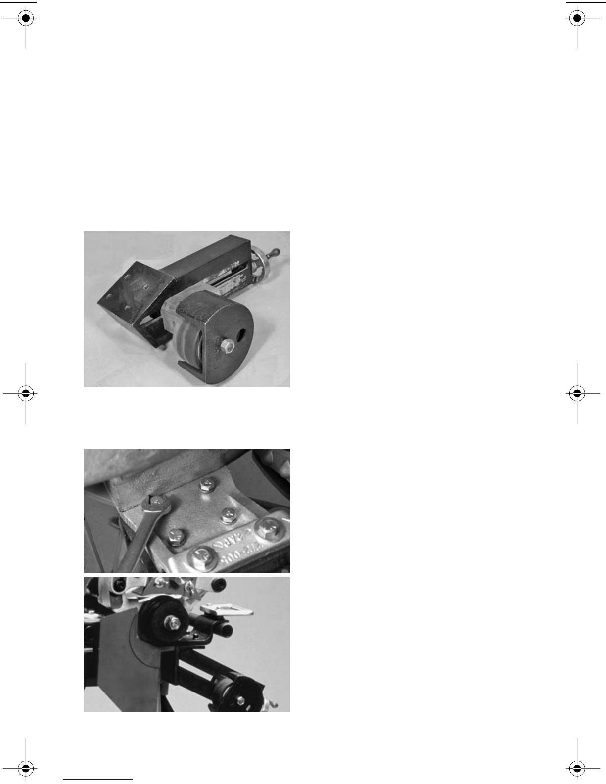
6. After every 40 hours of operation, clean
and lubricate the
3
/4-inch lower roll (if
equipped) and the 1 – 11/2-inch lower roll.
Lower Roll
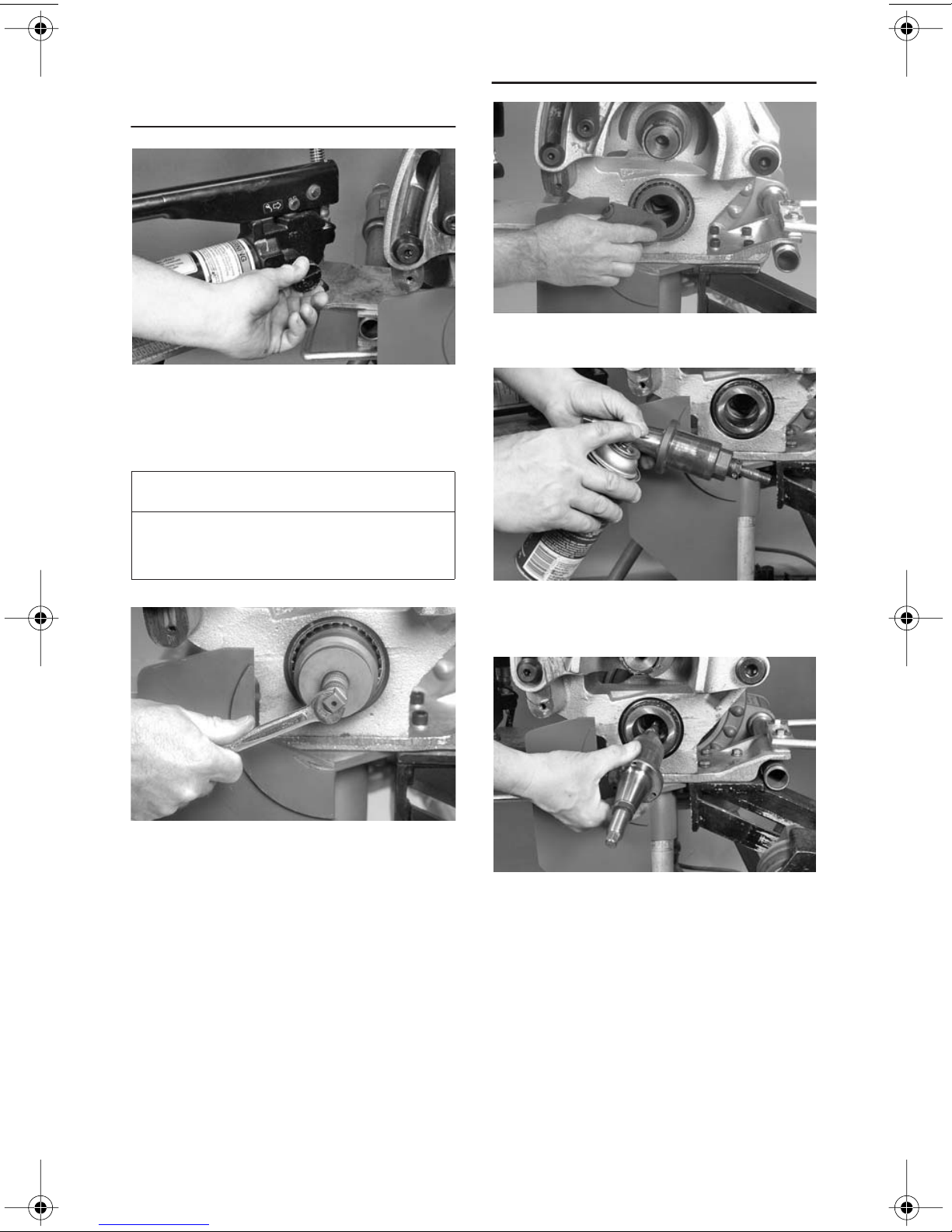
7. Remove the cap screws, and disassemble the two-piece collar. Remove both the
collar and the needle bearing, along with the
washers.
8. Remove the lower roll from the arbor.
Clean the 3/4-inch lower roll (if equipped) and
the 1 – 11/2-inch lower roll. Lightly lubricate the
lower rolls with dry graphite spray (supplied
with the tool and available from the Victaulic
Tool Company).
1. Open the hand pump valve by turning
the knob counterclockwise.
2. Remove the hand pump/pump support
from the tool base.
9. Re-assemble the 3/4-inch lower roll (if
equipped) and the 1 – 11/2-inch lower roll.
Lubricate the needle bearing with bearing
grease. Make sure the end gaps are uniform
on the two-piece collar.
VE272SFS Roll Grooving Tool 33
3. Loosen, but do not remove, the hydraulic
fill plug/dipstick at the back end of the pump.
Page 36

4. Hold the hand pump so that the fill plug
end is ABOVE the hydraulic cylinder. This will
prevent siphoning of oil from the hydraulic
cylinder through the hand pump.
5. Check the fluid level. Add hydraulic jack
oil (ISO 32) to the proper level, as required.
On models without a dipstick, remove the
cap. Oil should be approximately
1
/2 - 1 inch
(13 – 25 mm) from the end.
AIR BLEEDING
1. To bleed air from the system, hold the
entire hand pump above the hydraulic cylinder. Close the hand pump valve by turning the
knob clockwise. Open the fill plug one full
turn.
2. Pump the hand pump several times to
build pressure.
3. Open the hand pump valve by turning
the knob counterclockwise, and allow air to
escape.
4. Repeat steps 1 – 3 several times to bleed
all air from the system.
5. Check the oil level. Add more oil, if necessary.
6. Continue to hold the pump above the
hydraulic cylinder, and close the fill plug.
7. Install the hand pump/pump support
securely to the tool by following steps 15 – 17
of the “Tool Setup” section on page 9.
34 VE272SFS Roll Grooving Tool
Page 37

PARTS ORDERING
INFORMATION
When ordering parts, the following information
is required for the Victaulic Tool Company to
process the order and send the correct
part(s). Request the RP-272SFS Repair Parts
List for detailed drawings and parts listings.
1. Tool Model Number – VE272SFS
2. Tool Serial Number – The serial number
is stamped onto the tool body
3. Quantity, Part Number, and Description
– For example, (1), R029266MCH, Main Shaft
4. Where to Send the Part(s) – Company
name and address
5. To Whose Attention to Send the Part(s)
6. Purchase Order Number
VAPS 224 VICTAULIC ADJUSTABLE
PIPE STAND
The Victaulic VAPS 224 contains features that
are similar to the VAPS 112, but it is suitable
for 2 – 24-inch pipe sizes. Contact the Victaulic Tool Company for details.
VPD752 POWER DRIVE
Order parts from the Victaulic Tool Company
at the address listed in this manual.
ACCESSORIES
VAPS 112 VICTAULIC ADJUSTABLE
PIPE STAND
The Victaulic VAPS 112 is a portable, adjustable, roller-type pipe stand that contains four
legs for additional stability. Ball transfer rollers, adjustable for 3/4 - 12-inch pipe, accommodate linear and rotational movement. The
turnstile design permits ease of grooving for
both pipe ends. Contact Victaulic Tool Company for details.
The Victaulic VPD752 Power Drive can be
used as the power drive unit for several different roll grooving tool models with the correct
base plate. The power drive utilizes a 60 Hz
universal motor and requires 115V/1 Phase,
15 amps of power. A safety foot switch is included for proper operation. Contact the
Victaulic Tool Company for details.
VE272SFS Roll Grooving Tool 35
Page 38

STABILIZER ASSEMBLY
A pipe stabilizer is available to prevent pipe
sway on 8 – 12-inch pipe sizes. Contact the
Victaulic Tool Company for details.
OPTIONAL ROLLS
Refer to the "Tool Rating and Roll Selection"
section, starting on page 39, for rolls that are
available for different materials and groove
specifications.
36 VE272SFS Roll Grooving Tool
Page 39

TROUBLESHOOTING
Problem Possible Cause Solution
Pipe/tubing will not
stay in grooving rolls.
Pipe/tubing stops
rotating during
grooving.
Incorrect pipe/tubing
positioning of long pipe/tubing
length.
Lower roll and pipe/tubing are
not rotating clockwise.
Rust or dirt buildup is present
on the lower roll.
Rust or dirt is excessively
heavy inside the pipe/tubing
end.
Worn grooving rolls. Inspect the lower roll for worn knurls.
Power drive has stalled due to
excessive pumping of the hand
pump.
The circuit breaker has tripped
or a fuse has blown out on the
electrical circuit that supplies
the power drive.
Refer to the "Long Pipe/Tubing Lengths"
section on page 13.
Flip the switch on the power drive to the
opposite rotation position.
Remove rust or dirt accumulation from the
lower roll with a stiff wire brush.
Remove heavy rust and dirt from inside the
pipe/tubing end.
Replace the lower roll if excessive wear is
present.
Support the pipe/tubing. Open the hand
pump valve by turning the knob
counterclockwise. Close the hand pump
valve by turning the knob clockwise.
Continue grooving by pumping the hand
pump at a moderate rate.
Reset the breaker, or replace the fuse.
While grooving, loud
squeaks echo
through the pipe/
tubing.
During grooving,
loud thumps or
bangs occur
approximately once
every revolution of
the pipe/tubing.
Incorrect pipe/tubing support
positioning of long pipe/tubing.
Pipe/tubing is “over-tracking.”
Pipe/tubing end is not cut
square.
Pipe/tubing is rubbing
excessively on the lower roll
backstop flange.
Pipe/tubing has a pronounced
weld seam.
Move the pipe/tubing support to the right.
Refer to the "Long Pipe/Tubing Lengths"
section on page 13.
Cut the pipe/tubing end squarely.
Remove the pipe/tubing from the tool, and
apply a light coating of grease to the face of
the lower roll backstop flange, as needed.
Grind the raised welds flush with the interior
and exterior
(50 mm) back from the pipe/tubing end.
pipe/tubing surfaces 2 inches
VE272SFS Roll Grooving Tool 37
Page 40

Problem Possible Cause Solution
Pipe/tubing flare is
excessive.
Larger diameter pipe
sways or vibrates
from side to side.
The tool will not
groove the pipe/
tubing.
Pipe/tubing support adjusted
too high for long pipe/tubing.
Tool is tilted forward (out of
Refer to the "Long Pipe/Tubing Lengths"
section on page 13.
Refer to the "Tool Setup" section on page 7.
level) while grooving long pipe/
tubing.
Incorrect pipe/tubing support
positioning of long pipe/tubing.
Pipe/tubing is “over-tracking”.
Pipe stabilizer is adjusted too
far inward.
Move the pipe support to the right. Refer to
the "Long Pipe/Tubing Lengths" section on
page 13.
Back off the pipe stabilizer to the furthest
point where it still stabilizes the pipe
effectively.
Incorrect pipe stabilizer
adjustment.
Optional pipe stabilizer was not
purchased, installed, or used.
Hand pump valve is not closed
tightly.
Move the pipe stabilizer in or out until the
pipe rotates smoothly.
Purchase, install, or use the optional pipe
stabilizer.
Tighten the hand pump valve by turning the
knob clockwise.
Hand pump is low on oil. Refer to the "Maintenance" section on
page 32.
Pipe/tubing grooves
do not meet Victaulic
specifications.
The “A” Gasket Seat
or “B” Groove Width
dimensions do not
meet Victaulic
specifications.
Air is present in the hydraulic
system.
Pipe/tubing is beyond the wall
thickness capacity of the tool.
Groove diameter stop is not
adjusted correctly.
Pipe/tubing is beyond the wall
thickness capacity of the tool.
Upper roll bearing is not
lubricated adequately.
Incorrect upper roll, lower roll,
or both installed on the tool.
Refer to the "Maintenance" section on
page 32.
Refer to the "Tool Rating and Roll Selection"
section, starting on page 39.
Refer to the "Groove Diameter Stop
Adjustment" section on page 18.
Refer to the "Tool Rating and Roll Selection"
section, starting on page 39.
Refer to the "Maintenance" section, starting
on page 32.
Install the correct rolls. Refer to the "Tool
Rating and Roll Selection" section, starting
on page 39.
38 VE272SFS Roll Grooving Tool
Page 41

TOOL RATING AND ROLL SELECTION
STANDARD AND “ES” ROLLS FOR STEEL AND STAINLESS STEEL PIPE –
COLOR-CODED BLACK
(For 2 - 12-inch lightwall stainless steel pipe, refer to the table on page 41)
12
Pipe Size
Nominal
Actual Out.
Size
inches or mm
3
/
4
inches (mm)
Diameter
1.050
26,9
Steel Pipe Wall Thickness
Minimum Maximum Minimum Maximum
0.065
Dimensions – inches/millimeters
0.113
1,7
2,9
Stainless Steel Pipe
Wall Thickness
0.065
1,7
0.113
2,9
Standard
Roll Part
Numbers
Lower Roll
R9A0268L01
Upper Roll
R9A0268U02
Part Numbers
APPLICABLE
“ES”
Roll
NOT
1
11/
4
11/
2
2
21/
2
3
31/
2
4
41/
2
5
152,4 mm
6
203,2 mm
8
10
12
1.315 0.065 0.133 0.065 0.133
33,7 1,7 3,4 1,7 3,4
1.660 0.065 0.140 0.065 0.140
42,4 1,7 3,6 1,7 3,6
1.900 0.065 0.145 0.065 0.145
48,3 1,7 3,7 1,7 3,7
2.375 0.065 0.154 0.154 0.154
60,3 1,7 3,9 3,9 3,9
2.875 0.083 0.203 0.203 0.203
73,0 2,1 5,2 5,2 5,2
3.500 0.083 0.216 0.216 0.216
88,9 2,1 5,5 5,5 5,5
4.000 0.083 0.226 0.226 0.226
101,6 2,1 5,7 5,7 5,7
4.500 0.083 0.237 0.237 0.237
114,3 2,1 6,0 6,0 6,0
5.000 0.095 0.237 0.237 0.237
127,0 2,4 6,0 6,0 6,0
5.563 0.109 0.258 0.258 0.258
141,3 2,8 6,6 6,6 6,6
6.000 0.109 0.258 0.258 0.258
152,4 2,8 6,6 6,6 6,6
6.625 0.109 0.280 0.280 0.280
168,3 2,8 7,1 7,1 7,1
8.000 0.109 0.322 0.250 0.322
203,2 2,8 8,2 6,4 8,2
8.625 0.109 0.322 0.250 0.322
219,1 2,8 8,2 6,4 8,2
10.750 0.134 0.250 0.250 0.250
273,0 3,4 6,4 6,4 6,4
12.750 0.156 0.250 0.250 0.250
323,9 4,0 6,4 6,4 6,4
Lower Roll
R9A1268L02
Upper Roll
R9A0268U02
Lower Roll
R902272L03
Upper Roll
R9A2268U06
Lower Roll
R904272L06
Upper Roll
R9A2268U06
Lower Roll
R908272L12
Upper Roll
R9A8268U12
NOT
APPLICABLE
Lower Roll
RZ02272L03
Upper Roll
RZA2268U03
Lower Roll
RZ04272L06
Upper Roll
RZA4268U06
Lower Roll
RZ08272L12
Upper Roll
RZA8268U12
Notes:
Column 1: Maximum ratings on steel are limited to pipe of a Brinnel Hardness Number (BHN) of 180 BHN and less
Column 2: Types 304/304L and 316/316L stainless steel pipe
The wall thicknesses listed are nominal minimum and maximum
In addition, the following pipe sizes may be roll grooved: 76,1 mm; 108,0 mm; 127,0 mm; 133,0 mm; 139,7 mm; 159,0
mm; 165,1 mm; 216,3 mm; 267,4 mm; and 318,5 mm. Contact Victaulic Tool Company for details.
VE272SFS Roll Grooving Tool 39
Page 42

ROLLS FOR ALUMINUM AND PVC PLASTIC PIPE –
COLOR-CODED YELLOW ZINC
12
Pipe Size
Nominal
Actual Outside
Size
inches or mm
2
21/
2
3
31/
2
4
41/
2
5
152,4 mm
6
Diameter
inches (mm)
Minimum Maximum Minimum Maximum
2.375 0.065 0.154 0.154 0.154
60,3 1,7 3,9 3,9 3,9
2.875 0.083 0.203 0.203 0.276
73,0 2,1 5,2 5,2 7,0
3.500 0.083 0.216 0.216 0.300
88,9 2,1 5,5 5,5 7,6
4.000 0.083 0.226 0.226 0.318
101,6 2,1 5,7 5,7 8,1
4.500 0.083 0.237 0.237 0.337
114,3 2,1 6,0 6,0 8,6
5.000 0.095 0.237 - -
127,0 2,4 6,0 - -
5.563 0.109 0.258 0.258 0.375
141,3 2,8 6,6 6,6 9,5
6.000 0.109 0.258 - -
152,4 2,8 6,6 - -
6.625 0.109 0.280 0.280 0.432
168,3 2,8 7,1 7,1 11,0
Dimensions – inches/millimeters
Aluminum Pipe
Wall Thickness
PVC Plastic Pipe
Wall Thickness
Standard
Roll
Part Numbers
Lower Roll
R902272L03
Upper Roll
RP02272U06
Lower Roll
R904272L06
Upper Roll
RP02272U06
Notes:
Column 1: Alloys 6061-T4 and 6063-T4
Column 2: PVC Type 1, Grade 1 – PVC 1120; PVC Type 1, Grade II – PVC 1220; PVC Type II, Grade I – PVC 2116
The wall thicknesses listed are nominal minimum and maximum
In addition, the following pipe sizes may be roll grooved: 76,1 mm; 108,0 mm; 133,0 mm; 139,7 mm; 159,0 mm; and
165,1 mm. Contact Victaulic Tool Company for details.
A special lower roll is available for grooving 2-inch Schedule 80 PVC plastic pipe (part number RP02272L02). Contact
Victaulic Tool Company for details.
40 VE272SFS Roll Grooving Tool
Page 43
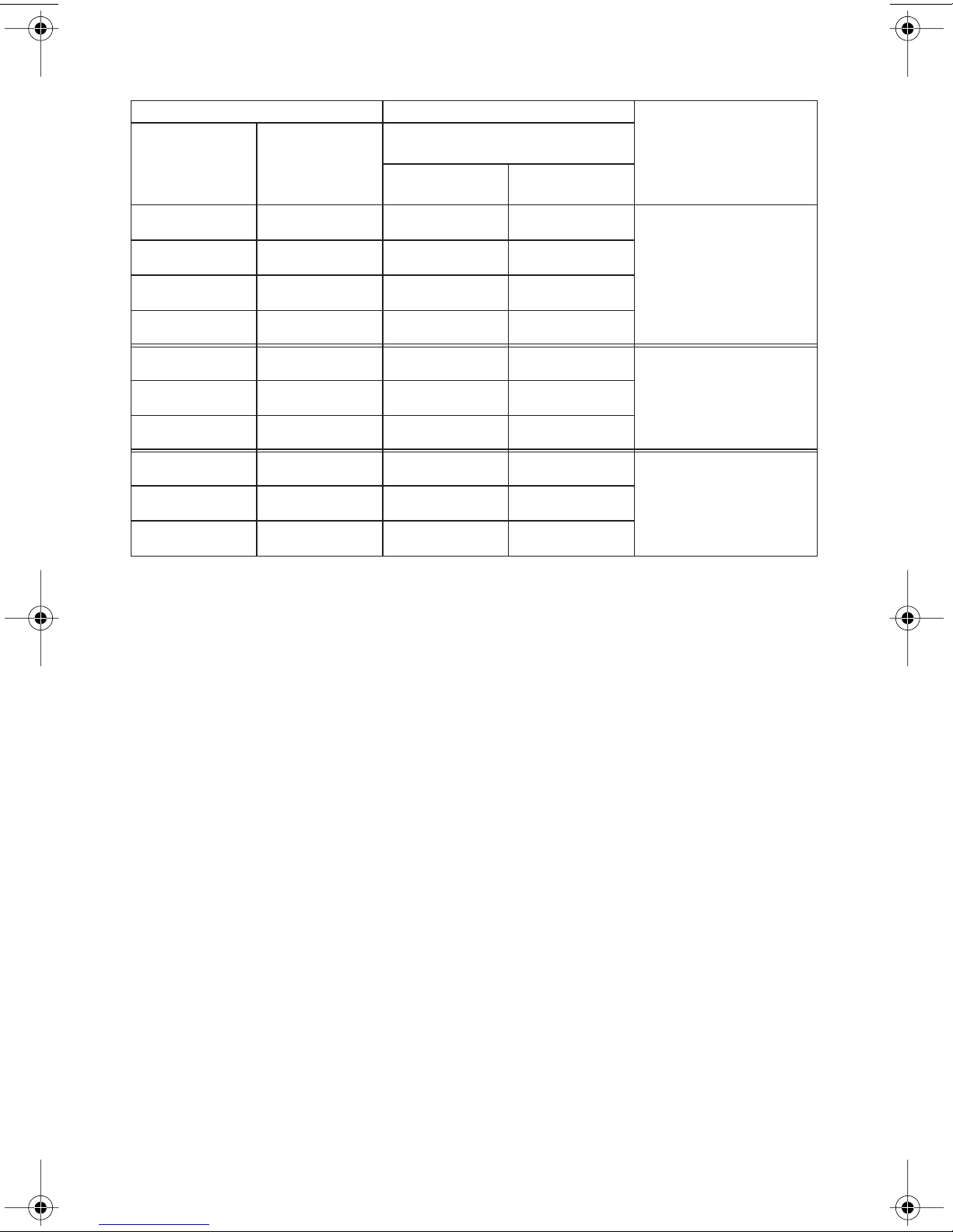
RX ROLLS FOR SCHEDULE 5S AND 10S STAINLESS STEEL PIPE –
COLOR-CODED SILVER
Pipe Size Dimensions – inches/millimeters
Stainless Steel Pipe ‡
Nominal Size
inches
2
21/
2
3
31/
2
4
5
6
8
10
12
Actual Outside
Diameter
inches (mm)
Minimum for
Schedule 5S
Wall Thickness
Maximum for
Schedule 10S
2.375 0.065 0.109
60,3 1,7 2,8
2.875 0.083 0.120
73,0 2,1 3,0
3.500 0.083 0.120
88,9 2,1 3,0
4.000 0.083 0.120
101,6 2,1 3,0
4.500 0.083 0.120
114,3 2,1 3,0
5.563 0.109 0.134
141,3 2,8 3,4
6.625 0.109 0.134
168,3 2,8 3,4
8.625 0.109 0.148
219,1 2,8 3,8
10.750 0.134 0.165
273,0 3,4 4,2
12.750 0.156 0.180
323,9 4,0 4,6
RX
Roll
Part Numbers
Lower Roll
RX02272L03
Upper Roll
RXA2268U06
Lower Roll
RX04272L06
Upper Roll
RXA2268U06
Lower Roll
RX08272L12
Upper Roll
RXA8268U12
Notes:
‡ Types 304/304L and 316/316L stainless steel pipe
The wall thicknesses listed are nominal minimum and maximum
In addition, the following pipe sizes may be roll grooved: 76,1 mm; 108,0 mm; 133,0 mm; 139,7 mm; 152,4 mm; 159,0
mm; 165,1 mm; and 203,2 mm. Contact Victaulic Tool Company for details.
VE272SFS Roll Grooving Tool 41
Page 44

ROLLS FOR CTS US STANDARD - ASTM DRAWN COPPER TUBING –
COLOR-CODED COPPER
Tube Size Dimensions – inches/millimeters
Actual Outside
Nominal Size
inches
2
21/
2
3
4
5
6
8
‡ ASTM B306, Type DWV and ASTM B88, Types K, L, M copper tubing
The wall thicknesses listed are nominal minimum and maximum
Diameter
inches (mm)
2.125 0.042 0.083
54,0 1,1 2,1
2.625 0.065 0.095
66,7 1,7 2,4
3.125 0.045 0.109
79,4 1,1 2,8
4.125 0.058 0.134
104,8 1,5 3,4
5.125 0.072 0.160
130,2 1,8 4,1
6.125 0.083 0.192
155,6 2,1 4,9
8.125 0.109 0.271
206,4 2,8 6,9
Copper Tubing Wall Thickness ‡
Minimum Maximum
Copper Roll
Part Numbers
Lower Roll
RR02272L06
Upper Roll
RRA2268U08
Lower Roll
RR08272L08
Upper Roll
RRA2268U08
ROLLS FOR EUROPEAN STANDARD – EN 1057 DRAWN COPPER TUBING –
COLOR-CODED COPPER
Dimensions – millimeters (inches)
Nominal Size
mm
54,0
64,0
66,7
76,1
88,9
108,0
133,0
159,0
Copper Tubing Wall Thickness
Minimum Maximum
1,2 2,0
0.047 0.079
2,0 2,0
0.079 0.079
1,2 2,0
0.047 0.079
1,5 2,0
0.059 0.079
2,0 2,0
0.079 0.079
1,5 2,5
0.059 0.098
1,5 3,0
0.059 0.118
2,0 3,0
0.079 0.118
Copper Roll
Part Numbers
Lower Roll
RRE1272L06
Upper Roll
RRE1272U06
NOTE: The European Standard (EN 1057) replaces the British Standard (BS 2871) and DIN Standard (DIN 1786).
However, to ensure proper product performance, refer to Tables X and Y in the British Standard (BS 2871).
42 VE272SFS Roll Grooving Tool
Page 45

ROLLS FOR AUSTRALIAN STANDARD – AS 1432 DRAWN COPPER TUBING –
COLOR CODED COPPER
Dimensions – millimeters (inches)
Nominal Size
mm
DN 50
DN 65
DN 80
DN 100
DN 125
DN 150
‡ Types A, B, and D
Copper Tubing Wall Thickness ‡
Minimum Maximum
0,9 1,6
0.035 0.063
0,9 1,6
0.035 0.063
1,2 2,0
0.047 0.079
1,2 2,0
0.047 0.079
1,4 2,0
0.055 0.079
1,6 2,6
0.063 0.102
Copper Roll
Part Numbers
Lower Roll
RRE1272L06
Upper Roll
RRE1272U06
VE272SFS Roll Grooving Tool 43
Page 46

EXPLANATION OF CRITICAL ROLL GROOVE DIMENSIONS
B
OD
AB
C
T
D
Standard Roll Groove
Outside Diameter (“OD”) Dimension – The outside diameter of roll grooved pipe must not vary
from the specifications listed in the following tables. The maximum allowable tolerance from
square-cut pipe ends is 0.030 inch (0,8 mm) for 3/4 - 31/2-inch sizes; 0.045 inch (1,1 mm) for 4 –
6-inch sizes; and 0.060 inch (1,5 mm) for 203,2 mm and larger sizes. This is measured from the
true square line.
“A” Dimension – The “A” dimension, or the distance from the pipe end to the groove, identifies
the gasket seating area. This area must be free from indentations, projections, and roll marks from
the pipe end to the groove to provide a leak-tight seal for the gasket.
“B” Dimension – The “B” dimension, or groove width, controls expansion and angular deflection
by the distance it is located from the pipe and its width in relation to the housings’ “key” width.
“C” Dimension – The “C” dimension is the proper diameter at the base of the groove. This
dimension must be within the diameter’s tolerance and concentric with the OD for proper coupling fit. The groove must be of uniform depth for the entire pipe circumference.
“D” Dimension – The “D” dimension is the normal depth of the groove and is a reference for a
“trial groove” only. Variations in pipe OD affect this dimension and must be altered, if necessary,
to keep the “C” dimension within tolerance. This groove must conform to the “C” dimension.
“F” Dimension (Standard Roll Groove Only) – Maximum allowable pipe-end flare diameter is
measured at the extreme pipe-end diameter.
“T” Dimension – The “T” dimension is the lightest grade (minimum, nominal wall thickness) of
pipe that is suitable for roll grooving (except for PVC pipe).
44 VE272SFS Roll Grooving Tool
Page 47

Max. Allow.
Min. Allow.
Groove
Flare Dia. “F”Max. Min. Basic Max. Min. Basic Max. Min. Max. Min.
Wall Thick. “T”
Depth “D” (ref.)
Pipe Outside Diameter Gasket Seat “A” Groove Width “B” Groove Diameter “C”
26,9 26,9 26,4 15,9 16,7 15,1 7,1 7,9 6,4 23,8 23,4 1,5 1,2 29,2
1.050 1.060 1.040 0.625 0.656 0.594 0.281 0.312 0.250 0.938 0.923 0.056 0.049 1.15
Actual OD
Inches (mm)
Pipe Size Dimensions – inches (millimeters)
Nominal Size
ROLL GROOVE SPECIFICATIONS
STEEL, STAINLESS STEEL, ALUMINUM, AND PVC PIPE
4
/
3
inches or mm
VE272SFS Roll Grooving Tool 45
1.315 1.328 1.302 0.625 0.656 0.594 0.281 0.312 0.250 1.190 1.175 0.063 0.049 1.43
1
33,7 33,7 33,1 15,9 16,7 15,1 7,1 7,9 6,4 30,2 29,9 1,6 1,2 36,3
42,4 42,6 41,8 15,9 16,7 15,1 7,1 7,9 6,4 39,0 38,6 1,6 1,2 45,0
1.660 1.676 1.644 0.625 0.656 0.594 0.281 0.312 0.250 1.535 1.520 0.063 0.049 1.77
4
/
1
1
48,3 48,7 47,8 15,9 16,7 15,1 7,1 7,9 6,4 45,1 44,7 1,6 1,2 51,1
1.900 1.919 1.881 0.625 0.656 0.594 0.281 0.312 0.250 1.775 1.760 0.063 0.049 2.01
2
/
1
1
2.375 2.399 2.351 0.625 0.656 0.594 0.344 0.375 0.313 2.250 2.235 0.063 0.049 2.48
2
60,3 60,9 59,7 15,9 16,7 15,1 8,7 9,5 8,0 57,2 56,8 1,6 1,2 63,0
73,0 73,8 72,3 15,9 16,7 15,1 8,7 9,5 8,0 69,1 68,6 2,0 2,0 75,7
2.875 2.904 2.846 0.625 0.656 0.594 0.344 0.375 0.313 2.720 2.702 0.078 0.078 2.98
2
/
1
2
76,1 77,0 75,4 15,9 16,7 15,1 8,7 9,5 8,0 72,3 71,8 2,0 2,0 78,7
3.000 3.030 2.970 0.625 0.656 0.594 0.344 0.375 0.313 2.845 2.827 0.078 0.078 3.10
3.500 3.535 3.469 0.625 0.656 0.594 0.344 0.375 0.313 3.344 3.326 0.078 0.078 3.60
76,1 mm
3
88,9 89,8 88,1 15,9 16,7 15,1 8,7 9,5 8,0 84,9 84,5 2,0 2,0 91,4
101,6 102,6 100,8 15,9 16,7 15,1 8,7 9,5 8,0 97,4 96,9 2,2 2,0 104,1
4.000 4.040 3.969 0.625 0.656 0.594 0.344 0.375 0.313 3.834 3.814 0.083 0.078 4.10
2
/
1
3
108,0 109,0 107,2 15,9 16,7 15,1 8,7 9,5 8,0 103,7 103,2 2,2 2,0 110,5
4.250 4.293 4.219 0.625 0.656 0.594 0.344 0.375 0.313 4.084 4.064 0.083 0.078 4.35
4.500 4.545 4.469 0.625 0.656 0.594 0.344 0.375 0.313 4.334 4.314 0.083 0.078 4.60
108,0 mm
114,3 115,4 113,5 15,9 16,7 15,1 8,7 9,5 8,0 110,1 109,6 2,2 2,0 116,8
4
127,0 128,3 126,2 15,9 16,7 15,1 8,7 9,5 8,0 122,8 122,3 2,2 2,0 129,5
5.000 5.050 4.969 0.625 0.656 0.594 0.344 0.375 0.313 4.834 4.814 0.083 0.078 5.10
2
/
1
4
133,0 134,7 132,6 15,9 16,7 15,1 8,7 9,5 8,0 129,1 128,6 2,2 2,0 135,9
5.250 5.303 5.219 0.625 0.656 0.594 0.344 0.375 0.313 5.084 5.064 0.083 0.078 5.35
5.500 5.556 5.469 0.625 0.656 0.594 0.344 0.375 0.313 5.334 5.314 0.083 0.078 5.60
133,0 mm
139,7 mm
139,7 141,1 138,9 15,9 16,7 15,1 8,7 9,5 8,0 135,5 135,0 2,2 2,0 142,2
141,3 142,7 140,5 15,9 16,7 15,1 8,7 9,5 8,0 137,0 136,5 2,2 2,0 143,8
5.563 5.619 5.532 0.625 0.656 0.594 0.344 0.375 0.313 5.395 5.373 0.084 0.078 5.66
5
Page 48

Max. Allow.
Min. Allow.
Groove
Flare Dia. “F”Max. Min. Basic Max. Min. Basic Max. Min. Max. Min.
Wall Thick. “T”
Depth “D” (ref.)
Pipe Outside Diameter Gasket Seat “A” Groove Width “B” Groove Diameter “C”
152,4 153,8 151,6 15,9 16,7 15,1 8,7 9,5 8,0 148,1 147,5 2,2 2,0 154,9
6.000 6.056 5.969 0.625 0.656 0.594 0.344 0.375 0.313 5.830 5.808 0.085 0.078 6.10
Actual OD
Inches (mm)
6.250 6.313 6.219 0.625 0.656 0.594 0.344 0.375 0.313 6.032 6.002 0.109 0.109 6.35
Pipe Size Dimensions – inches (millimeters)
ROLL GROOVE SPECIFICATIONS
Nominal Size
STEEL, STAINLESS STEEL, ALUMINUM, AND PVC PIPE
152,4 mm
inches or mm
46 VE272SFS Roll Grooving Tool
159,0 160,4 158,0 15,9 16,7 15,1 8,7 9,5 8,0 153,2 152,5 2,8 2,8 161,3
165,1 166,7 164,3 15,9 16,7 15,1 8,7 9,5 8,0 160,8 160,2 2,2 2,0 167,6
6.500 6.563 6.469 0.625 0.656 0.594 0.344 0.375 0.313 6.330 6.308 0.085 0.078 6.60
159,0 mm
165,1 mm
168,3 169,9 167,5 15,9 16,7 15,1 8,7 9,5 8,0 164,0 163,4 2,2 2,8 170,9
6.625 6.688 6.594 0.625 0.656 0.594 0.344 0.375 0.313 6.455 6.433 0.085 0.078 6.73
6
203,2 204,8 202,4 19,1 19,8 18,3 11,9 12,7 11,1 198,5 197,9 2,4 2,8 207,5
8.000 8.063 7.969 0.750 0.781 0.719 0.469 0.500 0.438 7.816 7.791 0.092 0.109 8.17
8.515 8.578 8.484 0.750 0.781 0.719 0.469 0.500 0.438 8.331 8.306 0.092 0.109 8.69
203,2 mm
216,3 217,9 215,5 19,1 19,8 18,3 11,9 12,7 11,1 211,6 211,0 2,4 2,8 220,7
219,1 220,7 218,3 19,1 19,8 18,3 11,9 12,7 11,1 214,4 213,8 2,4 2,8 223,5
8.625 8.688 8.594 0.750 0.781 0.719 0.469 0.500 0.438 8.441 8.416 0.092 0.109 8.80
8
216,3 mm
254,0 255,6 253,2 19,1 19,8 18,3 11,9 12,7 11,1 249,2 248,5 2,4 3,4 258,3
10.000 10.063 9.969 0.750 0.781 0.719 0.469 0.500 0.438 9.812 9.785 0.094 0.134 10.17
10.528 10.591 10.497 0.750 0.781 0.719 0.469 0.500 0.438 10.340 10.313 0.094 0.134 10.70
254,0 mm
267,4 269,0 266,6 19,1 19,8 18,3 11,9 12,7 11,1 262,6 262,0 2,4 3,4 271,8
273,0 274,7 272,3 19,1 19,8 18,3 11,9 12,7 11,1 268,3 267,6 2,4 3,4 277,4
10.750 10.813 10.719 0.750 0.781 0.719 0.469 0.500 0.438 10.562 10.535 0.094 0.134 10.92
10
267,4 mm
304,8 306,4 304,0 19,1 19,8 18,3 11,9 12,7 11,1 299,2 298,5 2,8 4,0 309,1
12.000 12.063 11.969 0.750 0.781 0.719 0.469 0.500 0.438 11.781 11.751 0.109 0.156 12.17
12.539 12.602 12.508 0.750 0.781 0.719 0.469 0.500 0.438 12.321 12.291 0.109 0.156 12.71
304,8 mm
318,5 320,1 317,7 19,1 19,8 18,3 11,9 12,7 11,1 313,0 312,2 2,8 4,0 322,8
323,9 325,5 323,1 19,1 19,8 18,3 11,9 12,7 11,1 318,3 317,5 2,8 4,0 328,2
12.750 12.813 12.719 0.750 0.781 0.719 0.469 0.500 0.438 12.531 12.501 0.109 0.156 12.92
12
318,5 mm
Page 49

Flare Dia.
Max. Allow.
Min.
Allow. Wall
Depth
“F”Max. Min. Max. Min. Max. Min. Max. Min.
Thick. “T”
“D” (ref.)
Pipe Outside Diameter Gasket Seat “A” Groove Width “B” Groove Diameter “C” Groove
(mm)
Act. Out.
Dia. inches
Pipe Size Dimensions – inches (millimeters)
Size
Nominal
ROLL GROOVE SPECIFICATIONS
STEEL PIPE AND ALL MATERIALS GROOVED WITH “ES” ROLLS
inches or mm
VE272SFS Roll Grooving Tool 47
60,3 60,9 59,7 14,5 14,0 6,7 6,4 57,2 56,8 1,6 3,9 63,0
2.375 2.399 2.351 0.572 0.552 0.265 0.250 2.250 2.235 0.063 0.154 2.480
2
73,0 73,8 72,3 14,5 14,0 6,7 6,4 69,1 68,6 2,0 5,2 75,7
2.875 2.904 2.846 0.572 0.552 0.265 0.250 2.720 2.702 0.078 0.203 2.980
2
/
1
2
88,9 89,8 88,1 14,5 14,0 6,7 6,4 84,9 84,5 2,1 5,5 91,4
3.500 3.535 3.469 0.572 0.552 0.265 0.250 3.344 3.326 0.083 0.216 3.600
3
114,3 115,4 113,5 15,5 15,0 8,1 7,6 110,1 109,6 2,1 6,0 116,8
4.500 4.545 4.469 0.610 0.590 0.320 0.300 4.334 4.314 0.083 0.237 4.600
4
168,3 169,9 167,5 15,5 15,0 8,1 7,6 164,0 163,4 2,2 7,1 170,9
6.625 6.688 6.594 0.610 0.590 0.320 0.300 6.455 6.433 0.085 0.280 6.730
6
219,1 220,7 218,3 18,3 17,8 10,4 9,9 214,4 213,8 2,3 8,2 223,5
8.625 8.688 8.594 0.719 0.699 0.410 0.390 8.441 8.416 0.092 0.322 8.800
8
273,0 274,7 272,3 18,3 17,8 10,4 9,9 268,3 267,6 2,4 9,3 277,4
10.750 10.813 10.719 0.719 0.699 0.410 0.390 10.562 10.535 0.094 0.365 10.920
10
323,9 325,5 323,1 18,3 17,8 10,4 9,9 318,3 317,5 2,8 9,5 328,2
12.750 12.813 12.719 0.719 0.699 0.410 0.390 12.531 12.501 0.109 0.375 12.920
12
Page 50

Dia.
Max. Allow. Flare
Min. Allow. Wall Thick.
Groove
Depth “D”
“F”Max. Min. Basic Max. Min. Max. Min. Max. Min.
“T”
(Ref. Only)
2.220
DWV*
3.220
DWV*
4.220
DWV*
5.220
DWV*
6.220
DWV*
8.220
DWV*
Copper Tubing
Outside Diameter ‡ Gasket Seat “A” Groove Width “B” Groove Diameter “C”
Copper
Tubing Size Dimensions – inches/millimeters
ROLL GROOVE SPECIFICATIONS
COPPER TUBING TO CTS US STANDARD – ASTM B-88 AND ASTM B-306
Nominal inches
48 VE272SFS Roll Grooving Tool
2.627 2.623 0.610 0.640 0.580 0.330 0.300 2.525 2.505 0.050 0.065 2.720
2
/
1
2 2.127 2.123 0.610 0.640 0.580 0.330 0.300 2.029 2.009 0.048
2
54,0 54,0 53,9 15,5 16,3 14,7 8,4 7,6 51,5 51,0 1,2 56,4
66,7 66,7 66,6 15,5 16,3 14,7 8,4 7,6 64,1 63,6 1,2 1,7 69,1
(Actual mm)
3 3.127 3.123 0.610 0.640 0.580 0.330 0.300 3.025 3.005 0.050
79,4 79,4 79,3 15,5 16,3 14,7 8,4 7,6 76,8 76,3 1,2 81,8
4 4.127 4.123 0.610 0.640 0.580 0.330 0.300 4.019 3.999 0.053
104,8 104,8 104,7 15,5 16,3 14,7 8,4 7,6 102,1 101,6 1,4 107,2
5 5.127 5.123 0.610 0.640 0.580 0.330 0.300 4.999 4.979 0.063
130,2 130,2 130,1 15,5 16,3 14,7 8,4 7,6 127,0 126,5 1,6 132,6
6 6.127 6.123 0.610 0.640 0.580 0.330 0.300 5.999 5.979 0.063
155,6 155,6 155,5 15,5 16,3 14,7 8,4 7,6 152,3 151,9 1,6 158,0
8 8.127 8.121 0.610 0.640 0.580 0.330 0.300 7.959 7.939 0.083
206,4 206,4 206,3 15,5 16,3 14,7 8,4 7,6 202,2 201,7 2,1 208,8
‡ The outside diameter of roll grooved copper tubing cannot vary from the tolerance listed. The maximum allowable tolerance from square cut ends is 0.030 inch (0,8 mm) for
2 – 3 inch (54,0 – 79,4 mm) sizes and 0.045 inch (1,1 mm) for 4 – 6 inch (104,8 – 155,6 mm) sizes; this is measured from the true square line.
* ASTM B-306 drain-waste and vent (DWV) is the minimum wall thickness of copper tubing that can be roll grooved.
Page 51

ROLL GROOVE SPECIFICATIONS
COPPER TUBING TO EUROPEAN STANDARD – EN 1057
Dimensions – millimeters/inches
Actual OD * Gasket Seat “A” Groove Width “B” Groove Diameter “C” Groove
Actual
Size
mm ‡
54
64
66,7
76,1
88,9
108
133
159
‡ European Standard Copper Tubing: Nominal EN 1057 drawn copper tubing size
* The outside diameter of roll grooved copper tubing cannot vary from the tolerance listed. The maximum allowable tolerance from square cut ends is 0,8 mm (0.030 inch) for 54 – 88,9 mm sizes and 1,1 mm (0.045 inch) for 108 – 159 mm
sizes; this is measured from the true square line.
54,07 53,93 15,87 16,64 15,11 8,38 7,62 51,51 51,00 1,25 56,39
2.129 2.123 0.625 0.655 0.595 0.330 0.300 2.028 2.008 0.049 2.220
64,07 63,93 15,87 16,64 15,11 8,38 7,62 61,47 60,96 1,27 66,41
2.522 2.517 0.625 0.655 0.595 0.330 0.300 2.420 2.400 0.050 2.615
66,77 66,63 15,87 16,64 15,11 8,38 7,62 64,14 63,63 1,27 69,09
2.629 2.623 0.625 0.655 0.595 0.330 0.300 .525 2.505 0.050 2.720
76,17 76,03 15,87 16,64 15,11 8,38 7,62 73,41 72,90 1,35 78,61
2.999 2.993 0.625 0.655 0.595 0.330 0.300 2.890 2.870 0.053 3.095
88,97 88,83 15,87 16,64 15,11 8,38 7,62 85,70 85,19 1,60 91,63
3.496 3.497 0.625 0.655 0.595 0.330 0.300 3.374 3.354 0.063 3.607
108,07 107,93 15,87 16,64 15,11 8,38 7,62 104,80 104,29 1,60 110,54
4.255 4.249 0.625 0.655 0.595 0.330 0.300 4.126 4.106 0.063 4.352
133,20 132,80 15,87 16,64 15,11 8,38 7,62 129,29 128,78 1,85 135,79
5.244 5.228 0.625 0.655 0.595 0.330 0.300 5.090 5.070 0.073 5.346
159,20 158,80 15,87 16,64 15,11 8,38 7,62 155,30 154,79 1,85 161,80
6.280 6.252 0.625 0.655 0.595 0.330 0.300 6.114 6.094 0.073 6.370
Depth
“D” (Ref.
Only)
Max.
Allow.
Flare Dia.
“F”Max. Min. Basic Max. Min. Max. Min. Max. Min.
COPPER TUBING TO AUSTRALIAN STANDARD – AS 1432
Dimensions – millimeters/inches
Actual OD * Gasket Seat “A” Groove Width “B” Groove Diameter “C” Groove
Nominal
Size ‡
mm
DN 50
DN 65
DN 80
DN 100
DN 125
DN 150
‡ Nominal AS 1432 drawn copper tubing size
* The outside diameter of roll grooved copper tubing cannot vary from the tolerance listed. The maximum allowable tolerance from square cut ends is 0,8 mm (0.030 inch) for DN 50 – 80 mm sizes and 1,1 mm (0.045 inch) for DN 100 –
150 mm sizes; this is measured from the true square line.
50,80 50,67 15,87 16,64 15,11 8,38 7,62 48,21 47,70 1,25 53,06
2.000 1.995 0.625 0.655 0.595 0.330 0.300 1.898 1.878 0.049 2.089
63,50 63,35 15,87 16,64 15,11 8,38 7,62 60,88 60,38 1,27 65,83
2.500 2.494 0.625 0.655 0.595 0.330 0.300 2.397 2.377 0.050 2.592
76,20 76,02 15,87 16,64 15,11 8,38 7,62 73,56 73,05 1,27 78,51
3.000 2.993 0.625 0.655 0.595 0.330 0.300 2.896 2.876 0.050 3.091
101,60 101,35 15,87 16,64 15,11 8,38 7,62 98,78 98,27 1,35 103,88
4.000 3.990 0.625 0.655 0.595 0.330 0.300 3.889 3.869 0.053 4.090
127,00 126,75 15,87 16,64 15,11 8,38 7,62 123,67 123,16 1,60 128,77
5.000 4.990 0.625 0.655 0.595 0.330 0.300 4.869 4.849 0.063 5.070
152,40 152,10 15,87 16,64 15,11 8,38 7,62 149,05 148,54 1,60 154,66
6.000 5.988 0.625 0.655 0.595 0.330 0.300 5.868 5.848 0.063 6.089
Depth
“D” (Ref.
Only)
Max.
Allow.
Flare
Dia. “F”Max. Min. Basic Max. Min. Max. Min. Max. Min.
VE272SFS Roll Grooving Tool 49
Page 52

Facilities Locations
R
Victaulic Companies
Phone: 1-800-PICK-VIC (1-800-742-5842)
FAX: 610/923-3090
e-mail: pickvic@victaulic.com
4901 Kesslersville Road • Easton, PA 18040 USA
VICTAULIC TOOL COMPANY VICTAULIC CONSTRUCTION PIPING SERVICES DIV.
P.O. Box 31 • Easton, PA 18044-0031 1818 Vultee Street • Allentown, PA 18103
Phone: 610/559-3300 • Fax: 610/923-3090 Phone: 610/559-3488 • Fax: 610/923-3170
e-mail: victools@victaulic.com e-mail: cps@victaulic.com
WORLD HEADQUARTERSCUSTOMER CARE CENTER
P.O. Box 31 • Easton, PA 18044-0031
Phone: 610/559-3300 • Fax: 610/250-8817
Victaulic Around the World
VICTAULIC COMPANY OF AMERICA
P.O. Box 31 • Easton, PA 18044-0031
Phone: 610/559-3300 • Fax: 610/250-8817
e-mail: victaulic@victaulic.com
VICTAULIC COMPANY OF CANADA VICTAULIC EUROPE
123 Newkirk Road • Richmond Hill, ON L4C 3G5 Prijkelstraat 36 • 9810 Nazareth, Belgium
Phone: 905/884-7444 • Fax: 905/884-9774 Phone: 32-9-381-15-00 • Fax: 32-9-380-44-38
e-mail: viccanada@victaulic.com e-mail: viceuro@victaulic.be
VICTAULIC AMERICA LATINA VICTAULIC ASIA-PACIFIC
P.O. Box 31 • Easton, PA USA 18044-0031 541 Orchard Road • #14-02, Liat Towers
4901 Kesslersville Road • Easton, PA USA 18040 Singapore 238881
Phone: 610/559-3300 • Fax: 610/559-3608 Phone: 65-6235-3035 • Fax: 65-6235-0535
e-mail: vical@victaulic.com e-mail: vicap@victaulic.com
www.victaulic.com
TM-VE272SFS 3776 Rev.B 11/04 SKU #WCAS-67APTU® Registered Trademark of Victaulic © Copyright 2004 Victaulic Printed in U.S.A. RM00272SFS
50 VE272SFS Roll Grooving Tool
 Loading...