

Page 1
TM-VE270FSD.2469 Rev.B Page 1 Sunday, October 28, 2001 4:10 PM
R
Operating and
Maintenance
Instructions
Manual
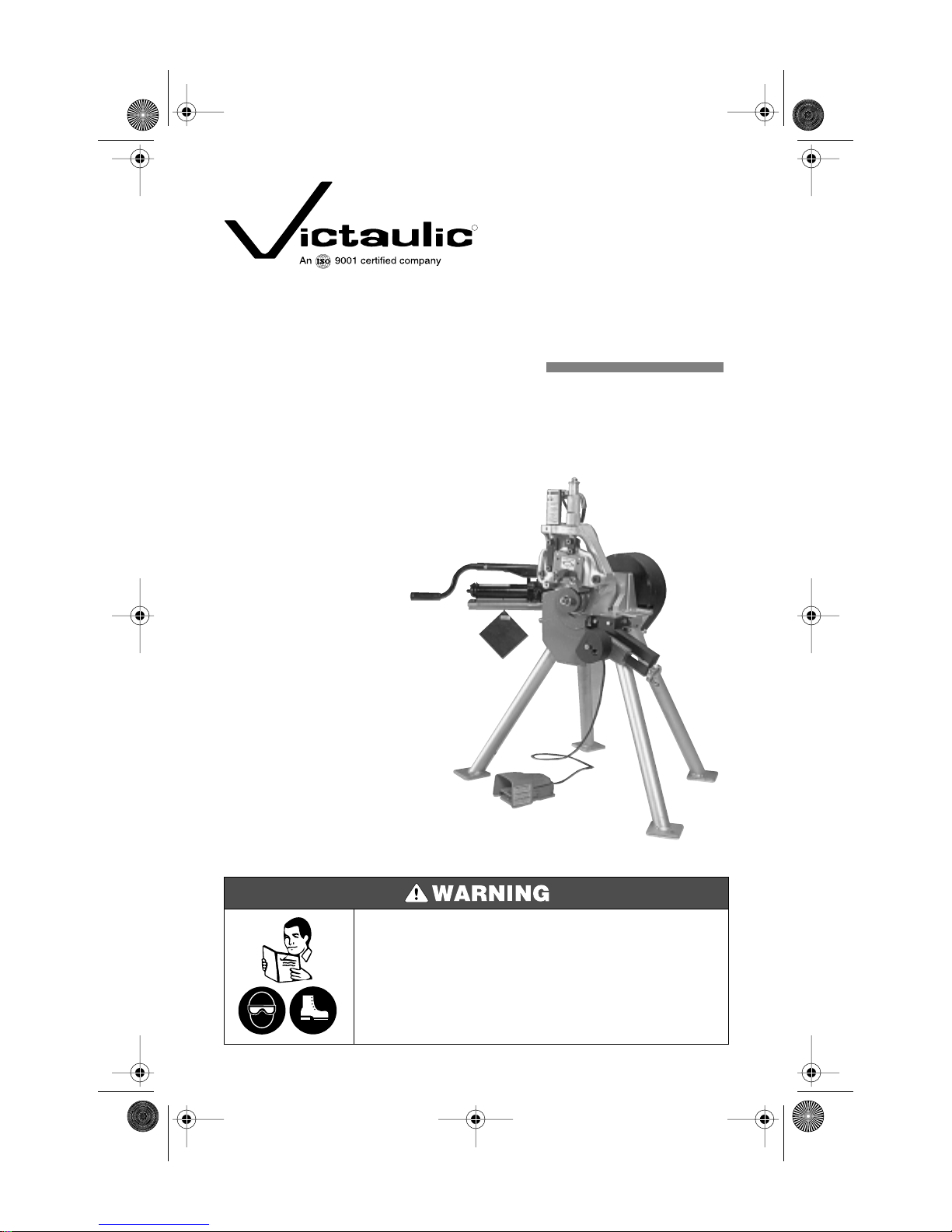
VE270FSD
Pipe Roll Grooving Tool
Failure to follow Instructions and warnings can result in serious personal injury.
• Before installing, operating or servicing the VE270FSD tool, read this Manual
and all warning labels on the tool.
• Always wear safety glasses and foot protection.
If you need additional copies of the manual or have any questions about the safe
operation of this tool, contact Victaulic Tool Company, P.O. Box 31, Easton, PA
18044-0031, Phone: 610-559-3300.
Page 2
TM-VE270FSD.2469 Rev.B Page 2 Sunday, October 28, 2001 4:10 PM
VE270FSD
INDEX
Hazard Identification . . . . . . . . . . . . . . . . . . . . . 2
Operator Safety Instructions. . . . . . . . . . . . . . . 3
General . . . . . . . . . . . . . . . . . . . . . . . . . . . . .3
Tool Setup . . . . . . . . . . . . . . . . . . . . . . . . . . .3
Operating Tool . . . . . . . . . . . . . . . . . . . . . . .3
Tool Maintenance. . . . . . . . . . . . . . . . . . . . . 3
Introduction . . . . . . . . . . . . . . . . . . . . . . . . . . . .4
Power Requirements . . . . . . . . . . . . . . . . . .4
Extension Cord Requirements . . . . . . . . . .4
Tool Nomenclature. . . . . . . . . . . . . . . . . . . . . . . 5
Receiving Tool . . . . . . . . . . . . . . . . . . . . . . . . . . 6
Container Contents . . . . . . . . . . . . . . . . . . .6
Tool Setup. . . . . . . . . . . . . . . . . . . . . . . . . . . . . . 6
Pre-Operation Adjustments . . . . . . . . . . . . . . . 7
Grooving Rolls. . . . . . . . . . . . . . . . . . . . . . . .7
Pipe Preparation . . . . . . . . . . . . . . . . . . . . . .7
Groovable Pipe Lengths. . . . . . . . . . . . . . . . 7
Roll Guard Adjustment. . . . . . . . . . . . . . . . . 9
Pipe Stabilizer Adjustment . . . . . . . . . . . .11
Groove Diameter Stop Adjustment. . . . . . 12
Grooving Operation . . . . . . . . . . . . . . . . . . . . . 14
Roll Changing. . . . . . . . . . . . . . . . . . . . . . . . . .16
Maintenance . . . . . . . . . . . . . . . . . . . . . . . . . .21
General . . . . . . . . . . . . . . . . . . . . . . . . . . . .21
Lubrication . . . . . . . . . . . . . . . . . . . . . . . . .21
Hydraulic Systems . . . . . . . . . . . . . . . . . . . 22
Parts Ordering Information . . . . . . . . . . . . . . .23
Accessories . . . . . . . . . . . . . . . . . . . . . . . . . . .24
Victaulic Adjustable Pipe Stands . . . . . . . 24
Stabilizer Assembly . . . . . . . . . . . . . . . . . . 24
Optional Rolls . . . . . . . . . . . . . . . . . . . . . . .24
Troubleshooting . . . . . . . . . . . . . . . . . . . . . . . . 25
Tool Rating and Roll Selection . . . . . . . . . . . .27
Standard and “ES” Rolls. . . . . . . . . . . . . . .27
Rolls for Stainless Steel (RX Rolls) . . . . . . .28
Rolls for Copper Tubing . . . . . . . . . . . . . . .28
Roll Groove Specifications. . . . . . . . . . . . . . . . 29
Steel Pipe and All Materials Grooved
with Standard and RX Rolls . . . . . . . . . .29
Drawn Copper Tubing . . . . . . . . . . . . . . . . 31
Steel Pipe and All Materials Grooved
with “ES” Rolls. . . . . . . . . . . . . . . . . . . . . 32
Dimensions. . . . . . . . . . . . . . . . . . . . . . . . . . . .33
Seamless and Welded Steel Pipe. . . . . . . .33
Drawn Copper Tubing . . . . . . . . . . . . . . . . 33
Read this First – Hazard Identification
Definitions for identifying the various hazard levels shown on warning labels or to indicate proper
safety procedures in this Manual are provided below.
This safety alert symbol indicates important safety messages on warning labels and in
this manual. When you see this symbol be alert to the possibility of personal injury and
carefully read and fully understand the message that follows.
The use of the word “DANGER” always signifies an
immediate hazard with a likelihood of serious
personal injury or death if instructions, including
recommended precautions, are not followed.
The use of the word “WARNING” signifies the
presence of hazards or unsafe practices which could
result in serious personal injury or death if
instructions, including recommended precautions, are
not followed.
NOTICE
The use of the word “CAUTION” signifies possible
hazards or unsafe practices which could result in
personal injury, product or property damage if
instructions, including precautions, are not followed.
The use of the word “NOTICE” signifies special
instructions which are important but not related to
hazards.
2
Page 3
TM-VE270FSD.2469 Rev.B Page 3 Sunday, October 28, 2001 4:10 PM
VE270FSD
OPERATOR SAFETY INSTRUCTIONS
This tool is designed only for roll grooving pipe. To accomplish this function requires some dexterity
and mechanical skills, as well as sound safety habits. Although this tool is manufactured for safe
dependable operation, it is impossible to anticipate those combinations of circumstances which
could result in an accident. The following instructions are recommended for safe operation of the
tool. The operator is cautioned to always practice “Safety First” during each phase of use, including
setup and maintenance of this unit. It is the responsibility of the owner, lessee or user to
ensure that all operators receive, read and understand this manual and are fully trained
to operate this tool.
GENERAL
1.
Read and understand this Manual before operating or performing maintenance on this tool.
Become familiar with the tool’s operations, applications and limitations. Be particularly aware of its specific
hazards. Store this manual in a clean area and always at a readily available location. Additional copies at no
charge are available upon request by writing or phoning the Victaulic Tool Company.
2.
Use only recommended accessories. Use of improper accessories may be hazardous. See Accessories on
page 24.
3.
This tool is designed ONLY for roll grooving of pipe sizes, materials and wall thicknesses
outlined under Tool Rating and Roll Selection, pages 27 and 28.
TOOL SETUP
1.
Ground the drive motor. Be sure the drive motor is connected to an internally grounded electrical system.
Avoid dangerous environments. Don’t use the machine in damp or wet locations. Don’t use the tool on
2.
sloped or uneven ground or floor. Keep work area well illuminated. Allow sufficient space to operate tool and
accessories properly and for others to pass safely.
3.
Prevent back injury. During tool setup, a lift must be used to handle and position tool.
OPERATING TOOL
1.
Inspect the equipment. Prior to starting the tool, check the movable parts for any obstructions. Be sure that
guards and tool parts are properly installed and adjusted.
2.
Prevent accidental startings.
3.
Operate with foot switch only. The VE270FSD must be operated with a safety foot switch, located for easy
operator access. The switch should always be accessible to the operator.
4.
Keep hands away from grooving rolls and stabilizer wheel during grooving operation. Grooving
rolls can crush or cut fingers and hands.
5.
Never reach inside pipe ends during operation.
Do not over-reach. Keep your proper footing and balance at all times. Be sure you can reach foot switch
6.
safely at all times. Do not reach across tool or pipe. Keep hands and loose tools away from moving parts.
7.
Wear safety glasses and footwear.
8.
Keep work area clean. Cluttered areas, benches and slippery floors invite accidents.
9.
Wear ear protection if exposed to long periods of very noisy shop operations.
10.
Keep visitors away. All visitors should be kept a safe distance from the work area.
11.
Keep alert. Do not operate tool if ill or drowsy from medication or fatigue. Avoid horseplay around tool and
keep bystanders a safe distance from tool and pipe being grooved.
Wear proper apparel. Never wear loose clothing (unbuttoned jackets or loose sleeve cuffs) loose gloves or
12.
jewelry that can get caught in moving parts.
13.
Do not force tool. It will do the job better and safer at the rate for which it was designed.
Secure work, tool and accessories. Make sure tool is stable. See “Tool Setup” for securing to floor or
14.
platform.
Support work. Support long pipe with a pipe stand secured to the floor or ground.
15.
16.
Do not misuse tool. Perform only the functions for which the tool is designed. Do not overload the tool.
TOOL MAINTENANCE
Unplug power cord prior to servicing. Repair should be attempted only by authorized personnel. Always
1.
unplug the tool before servicing.
2.
Maintain tool in top condition. Keep tool clean for best and safest performance. Follow lubricating
instructions.
Use only genuine Victaulic replacement parts to ensure proper and safe function of the tool.
3.
3
Page 4
TM-VE270FSD.2469 Rev.B Page 4 Sunday, October 28, 2001 4:10 PM
NOTICE
Drawings and/or pictures in this manual may be exaggerated for clarity.
VE270FSD
INTRODUCTION
All Victaulic Vic-Easy
of pipe to prepare it to receive Victaulic grooved pipe couplings. The VE270FSD is a completely selfcontained unit with a gear motor, safety foot switch and power cord/plug. The VE270FSD is
designed to roll groove pipe of various materials and wall thicknesses (see Tool Rating and Roll
Selection charts on pages 27 and 28.)
This tool and manual contains trademarks, copyrights and/or patented features which are the exclusive property of Victaulic Company of America.
• This tool should be used only for roll grooving pipe designated in the Tool Rating and Roll Selection charts on pages
27 and 28.
• Use of the tool for other purposes or exceeding the pipe thickness maximums will overload the tool, shorten tool life
and may cause tool damage.
POWER REQUIREMENTS
Power must be supplied through a safety foot switch to ensure safe operation. Be sure the tool is
properly grounded in accordance with Article 250 of the National Electrical Code. If an extension
cord is to be used, see Extension Cord Requirements for cord size recommendations.
®
Series 270FSD tools are semi-automated hydraulic feed tools for roll grooving
• To reduce the risk of electric shock, check the electrical source for proper grounding and follow
the instructions below.
• Before performing any repair or maintenance, disconnect the tool from the electrical source.
Failure to do so could result in death or serious personal injury.
EXTENSION CORD REQUIREMENTS
When pre-wired outlets are not available and an extension cord must be used, it is important to use
the proper cord size (e.g., conductor size American Wire gauge). Cord size selection is based upon
tool rating (amps) and cord length (feet). Use of a cord size (gauge) thinner than required will cause a
significant voltage drop at the gear motor while the tool is operating. The voltage drop may cause
damage to the gear motor and can result in failure of the tool to operate properly. Use of a heavier
than necessary cord size (gauge) is acceptable.
Listed in the chart below are recommended cord size (gauge) for cord lengths up to and including
100 feet. Use of extension cords beyond 100 feet in length should be avoided.
Tool
VE270FSD 115/15 12 12 10
Tool Rating
Volt/Amps
Cord Lengths
25' 50' 100'
4
Page 5
TM-VE270FSD.2469 Rev.B Page 5 Sunday, October 28, 2001 4:10 PM
VE270FSD
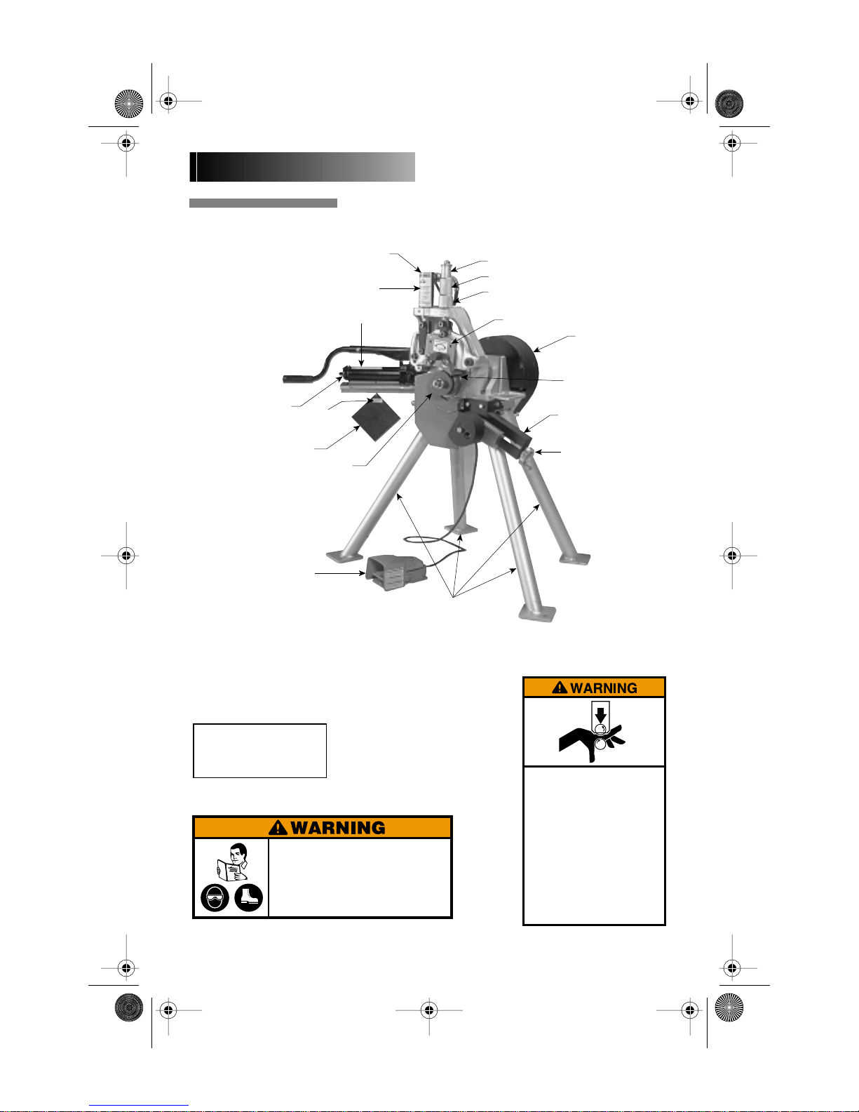
TOOL NOMENCLATURE
Hydraulic Pump
Guard Setting Pad
Foot Switch
Hydraulic Cylinder
➁
➂
Lower Roll
➀
Pipe Size Indicator
Depth Adjuster
Depth Adjuster Lock
Upper Roll
Motor/Drive
Guards
Stabilizer Assembly
Stabilizer Handwheel
Legs
➂
ALWAYS KEEP THIS PAD WITH THE
TOOL. USE IT TO SET THE GUARDS
IN ACCORDANCE WITH THE TOOL
OPERATION AND MAINTENANCE
MANUAL.
R068272LAB
➁
Failure to follow instructions and warnings can result in
serious injury, property damage, or faulty installation.
• Before installing, operating, or servicing this tool, read and
understand the Operating Instructions and all warning
labels on this tool.
• Always wear safety glasses and foot protection.
If you have any questions about the safe operation of this tool,
contact Victaulic Tool Company, P.O. Box 31, Easton, PA 18044-0031,
0567 Rev.A R031272LAB 3/99
5
610-559-3300.
➀
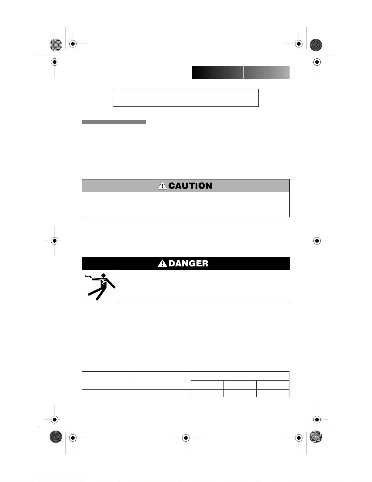
Grooving rolls can crush or cut
fingers and hands.
• Always unplug the power cord before
adjusting guard.
• Be sure guard is properly adjusted
before grooving pipe.
• Keep hands away from grooving
rolls and stabilizer wheel.
• Never reach inside pipe end or across
the tool or pipe during operation.
• Never groove pipe shorter than what
is recommended.
• Never wear loose clothing, loose
gloves or jewelry while operating tool.
2244 Rev.B 3/98 R007276LBL
Page 6

TM-VE270FSD.2469 Rev.B Page 6 Sunday, October 28, 2001 4:10 PM
1.
2.
3.
4.
5.
6.
7.
8.
1.
2.
a.
b.
c.
3.
4.
VE270FSD
RECEIVING TOOL
VE270FSD tools are palletized individually and
covered with a cardboard sleeve designed for
use in re-shipping tools.
NOTE: Be sure to save original shipping con-
tainer for return shipment of rental tools.
VE270FSD CONTAINER
CONTENTS
Upon receipt of tool, make sure all necessary
parts are included. If any parts are missing,
notify your Victaulic distributor or Victaulic
representative.
TOOL SETUP
• Do not plug in tool until instructed otherwise.
Accidental start up of tool may result in serious
personal injury.
Remove all components and check to be
sure all necessary items are included. See list
under Receiving Tool.
Select location for tool and pipe stand.
Choose a location that has:
The required power. Consult Power
Requirements on page 4.
The space necessary to adequately
handle the pipe to be grooved.
A level and even surface for tool, pipe
stand and footing.
During tool setup, one person cannot safely handle the
tool because it weighs 375 lbs. If a hoist is available,
use it to lift the tool head assembly into position.
Failure to follow this instruction may result in serious
personal injury.
Place tool on level floor or platform. Using
holes provided in feet, secure tool to the platform or floor. The tool’s legs are adjustable in
length to compensate for uneven surfaces.
Adjust as necessary to maintain tool levelness.
Tool head with mounting table and gear motor,
(4) legs and foot switch with cord and pump/pump
support assembly.
Rolls for 1 - 1 ¹⁄₂ ", 2 - 3 ¹⁄₂ ", 4 - 6" and 8 - 12" steel
pipe. The 8 - 12" rolls are mounted on the head
assembly.
Two (2) VE270FSD Operating and Maintenance
Instructions Manuals.
Guard setting pad.
Lower roller removal wedge.
Stabilizer with mounting hardware, if ordered.
Spare Woodruff keys.
One (1) 11 oz. can of Dow Corning G-n
Mechanical Assembly Spray.
The standard Series VE270FSD tools are supplied
with grooving rolls for 1 - 12" carbon steel pipe.
Rolls are marked with the size and part number
and color coded for pipe material, for your convenience. For grooving to other specifications and
other materials, see Tool Rating and Roll Selection
charts on pages 27 and 28. Grooving rolls for other
specifications, sizes and other materials must be
purchased separately.
Level the tool front to back. The top of the
hydraulic ram is a good location to measure
“level”.
6
Page 7
TM-VE270FSD.2469 Rev.B Page 7 Sunday, October 28, 2001 4:10 PM
VE270FSD
GROOVING ROLLS
Make sure the proper roll set is on the tool for
the pipe size and material to be grooved. They
are marked with the pipe size, part number
and color coded for the pipe material to be
grooved. See Tool Rating and Roll Selection
charts on pages 26 and 27. If proper rolls are
not on tool, refer to Roll Changing on page 16.
• Make sure roll retaining bolts and nuts are tight.
Loose retaining bolts or nuts could seriously damage
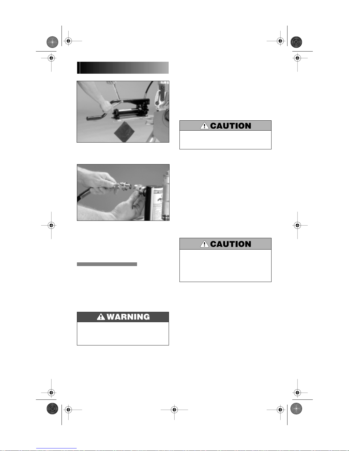
Insert the hand pump handle into lever arm
of the pump. Position handle with handle grip
down. Lock handle in this position with set
screw or nut and bolt provided.
Connect the hydraulic line from the pump
to the power cylinder using connectors provided.
VE270FSD tool setup is complete.
both the tool and rolls.
PIPE PREPARATION
For proper tool operation, and production of
proper pipe grooves, carefully observe the following pipe preparation tips.
Pipe ends should be cut squarely in accordance with Column 2 note on appropriate Roll
Groove Specification chart, pages 29 - 32.
Internal or external weld bead or seams
must be ground flush with the pipe surface
extending 2" back from the pipe end.
The end of the pipe, both inside and out,
must be cleaned of loose rust, coarse scale, dirt
and other foreign material.
5.
6.
1.
2.
3.
4.
PRE-OPERATION
ADJUSTMENTS
Every Vic-Easy tool is checked, adjusted and
tested at the factory prior to shipment. Before
grooving, however, the following adjustments
must be made in sequence to make sure of
proper tool operation.
• Always unplug power cord before making any tool
adjustments, unless instructed otherwise.
Accidental start up of tool may result in serious
personal injury.
7
For maximum grooving roll life, remove foreign
material and loose rust.
• Foreign material such as coarse scale or dirt might
interfere with or damage the grooving rolls or
distort the groove. Rust is an abrasive material and
will tend to wear out the surface of grooving rolls.
Victaulic recommends that pipe shall be
square ended. When using beveled pipe, standard wall or less, the bevel should not exceed
37 ¹⁄₂ °. Square ended pipe must be used with
FlushSeal
pipe walls, square ended pipe is required.
®
and EndSeal
®
gaskets. For heavier
GROOVABLE PIPE LENGTHS
The VE270FSD is capable of grooving short
pipe lengths without the use of a pipe stand
(see Table 1 on page 8), or long pipe lengths up
to double randoms (approximately 40 ft.), with
the use of appropriate stands.
Page 8
TM-VE270FSD.2469 Rev.B Page 8 Sunday, October 28, 2001 4:10 PM
VE270FSD
SHORT PIPE LENGTHS
Table 1 shows minimum and maximum pipe
lengths that can be grooved hands-off without
the need for a pipe stand. You do not have to
manually guide the pipe while grooving. For
pipe longer than shown in Table 1, refer to
Long Pipe Lengths at right.
Grooving rolls can crush or cut fingers
and hands.
• Loading and unloading pipe will
place your hands close to the
rollers.
• Never groove pipe shorter than what
is recommended in Table 1 below.
TABLE 1
VE270FSD GROOVABLE PIPE LENGTHS
2468-1A
DIMENSIONS – (Inches/mm)
Nom.
Min.
Max.
Nom.
Min.
Size
Length
Length
³⁄₄ 8364¹⁄₂ 832
20 203.2 914.4 115 203.2 812.8
18 3658 32
25 203.2 914.4 125 203.2 812.8
1¹⁄₄ 836
32 203.2 914.4 254.0 762.0
1¹⁄₂ 8 36 6 10 28
40 203.2 914.4 150 254.0 711.2
28 36
50 203.2 914.4 254.0 609.6
2¹⁄₂ 8 36 8 10 24
65 203.2 914.4 200 254.0 609.6
3 8 36 10 10 20
80 203.2 914.4 250 254.0 508.0
3¹⁄₂ 836121218
90 203.2 914.4 300 304.8 457.2
48 36
100 203.2 914.4
Size
6 O.D.
8 O.D.
Length
Max.
Length
10 30
10 24
If a pipe shorter than the minimum shown in
Table 1 is needed, if possible, shorten the next
to last piece of pipe enough so that the last
piece of pipe is as long or longer than the minimum length specified in Table 1. See example
at right.
NOTICE
Pipe nipples shorter than those shown in Table 1 are
available from Victaulic.
Example: A 20' 4" length of 10" diameter pipe
is needed to finish a section and you only have
20' lengths available. Instead of roll grooving a
20' piece of pipe and a 4" piece of pipe, follow
these steps:
1. Refer to Table 1 and note that for 10" diameter pipe, the minimum length that should be
grooved is 10".
2. Roll groove a 19' 6" piece of pipe and a 10"
piece of pipe. Refer to Long Pipe Lengths
below.
LONG PIPE LENGTHS
With pipe in excess of the maximum length
shown in Table 1, a roller type pipe stand must
be used.
NOTICE
Figure 1 shows the Victaulic adjustable pipe stand
(VAPS 112). VAPS 112 is suitable for ³⁄₄" to 12" pipe.
Also available is Victaulic model VAPS 224 suitable
for sizes 2" to 24". See Accessories on page 24.
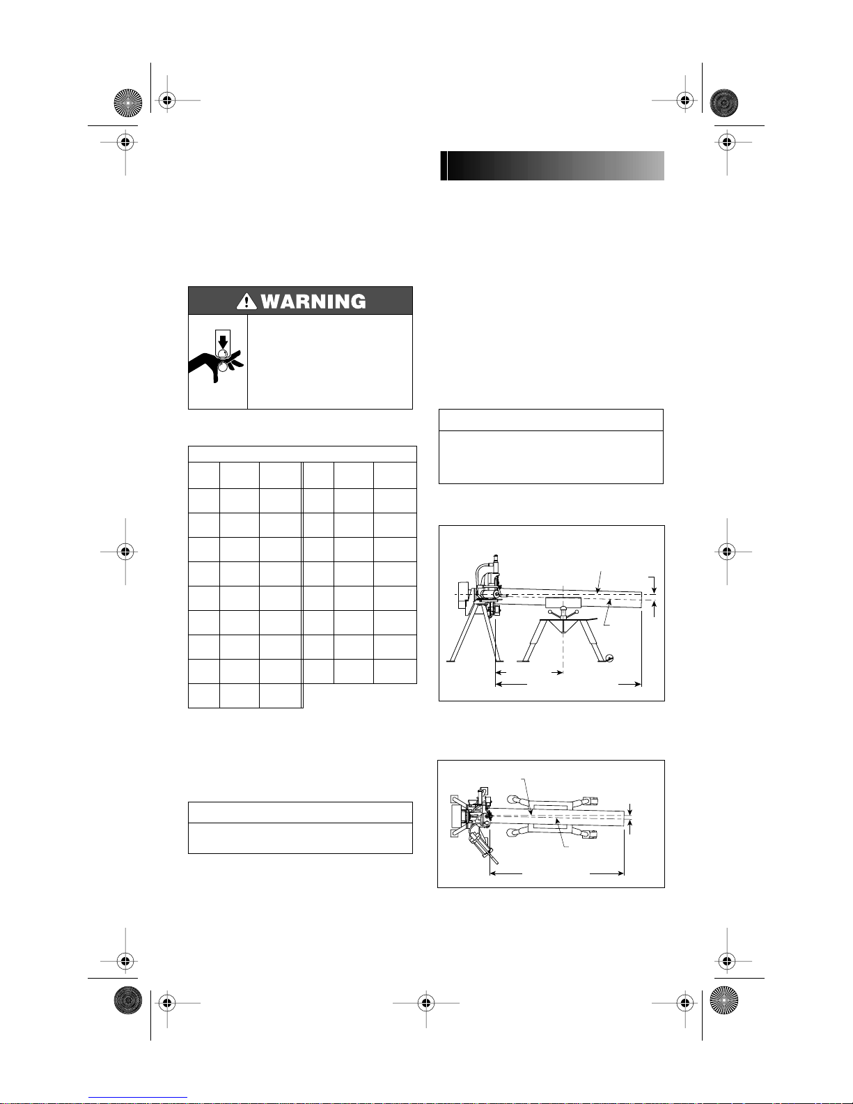
1. Position pipe and pipe stand in accordance
with Figures 1 and 2.
Tool
Pipe angle
Pipe Centerline
Centerline
(Level)
Centerline
0° to ¹⁄₂° Max.
¹⁄₂° to 1°
(2 to 4")
Pipe
(0 to 2")
Pipe angle
exaggerated for clarity
10' +1' -0
SUPPORT OF PIPE
Tool Centerline
20 Ft. Length of Pipe
Figure 1
exaggerated for clarity
20 Ft. Length of Pipe
TRACKING ANGLE
Figure 2
8
Page 9
TM-VE270FSD.2469 Rev.B Page 9 Sunday, October 28, 2001 4:10 PM
VE270FSD
• Pipe stand location will affect pipe tracking.
• Incorrect pipe stand position may result in pipe
being pushed out of rolls and falling.
Failure to position pipe and pipe stand in accordance
with Figures 1 and 2 (shown on page 8) may result in
serious personal injury or property damage.
Pipe position will affect pipe flare.
• When pipe end flare is excessive, right-to-left
tracking must be kept to a minimum. It may be
necessary to use less than ¹⁄₂ degree.
Make sure tool is level (see Tool Setup).
• If pipe is grooved with back end of pipe (end of pipe
which is not in tool) higher than the end being
grooved, pipe may not track and excessive pipe end
flare may result.
• Assembly of couplings on pipe exceeding Maximum
Allowable Flare, Column 8 in the Roll Groove
Specifications charts, pages 29 - 32, may prevent
closure of couplings pad-to-pad, allowing possible
pipe separation, and result in property damage.
• Also, joint leakage may result due to excessive
gasket distortion/damage.
NOTICE
For additional information about pipe stands, refer to
the Operating Instructions included with your pipe
stand.
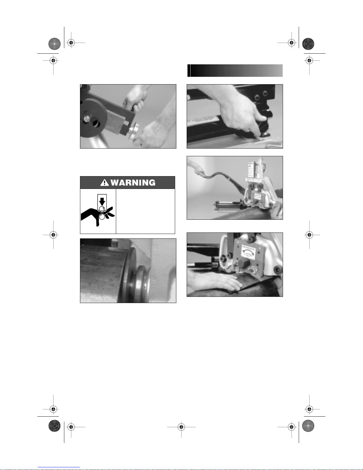
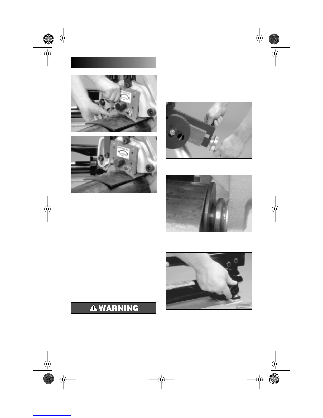
ROLL GUARD ADJUSTMENT
The VE270FSD guards must be adjusted every
time rolls are changed or pipe size or wall
thickness is different from previous pipe
grooved.
1. Make sure the proper roll set is on the tool
for the pipe size and material to be grooved.
Rolls are marked with the pipe size, part number and are color coded for pipe material for
your convenience. See Tool Rating and Roll
Selection charts pages 27 and 28. If the proper
rolls are not on the tool, refer to Roll Changing
on page 16.
2. Loosen wing nuts and move the adjustable
guards to the full up position. Tighten wing
nuts.
• Always unplug the power cord before making any
roll guard adjustments.
Accidental start up of tool may result in serious
personal injury.
9
3. Set groove diameter stop to pipe size and
schedule/thickness to be grooved. To do this,
back off the depth adjuster lock, align the
depth adjuster with the proper diameter and
thickness. Lock the depth adjuster in position
with the depth adjuster lock.
Page 10
TM-VE270FSD.2469 Rev.B Page 10 Sunday, October 28, 2001 4:10 PM
VE270FSD
4. If so equipped, retract stabilizer, if neces-
sary, to insert pipe. To do this, loosen locking
handle and retract stabilizer roller with the
hand wheel to clear pipe when inserted onto
lower roll.
Grooving rolls can crush or cut
fingers and hands.
• Loading and unloading pipe
will place your hands close to
the rollers.
• Never groove pipe shorter
than what is recommended in
Table 1 on page 8.
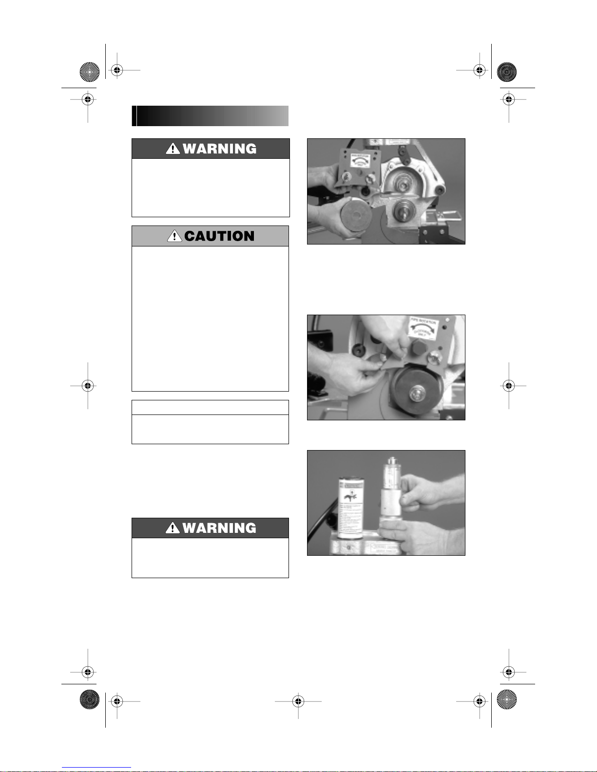
5. Insert a piece of pipe of the correct size and
schedule/thickness to be grooved over the
lower roll with the pipe end against the lower
roll backstop flange. See Pipe Preparation on
page 7.
6. Close hand pump valve.
7. Pump upper roll down into firm contact
with pipe.
8. Remove the guard setting pad from its storage hook beneath the pump support. Hold the
guard setting pad firmly down against the pipe
and push it under the adjustable guards flush
against the red plate.
10
Page 11
TM-VE270FSD.2469 Rev.B Page 11 Sunday, October 28, 2001 4:10 PM
VE270FSD
1. Make sure proper roll set is on the tool for
the pipe size and material to be grooved. Rolls
are marked with pipe size, part number and are
color coded for pipe material for your convenience. See Tool Rating and Roll Selection
charts on pages 27 and 28.
2. Loosen locking handle. With the hand
wheel, retract stabilizer roller to clear pipe
when inserted onto lower roll.
9. Loosen the wing nuts and adjust each
guard to conform to and lightly pinch the pad
against the pipe. Tighten wing nuts to secure
guards in position.
10. Remove the guard setting pad. Store the
pad back on the hook provided under pump
base.
PIPE STABILIZER
ADJUSTMENT
(Applies only to tools equipped with the optional stabilizer.)
The Series VE270FSD Pipe Stabilizer (Optional)
is designed to prevent pipe sway on 8" through
12" nominal IPS pipe sizes. This applies to
short as well as long pipes. Once the stabilizer
is adjusted for a selected pipe size and wall
thickness, it does not require further adjustment on that size and thickness. Pipe of the
same size and thickness may be moved in and
out of the tool without retracting stabilizer.
• Unplug power cord until instructed otherwise.
Accidental start up of tool may result in serious
personal injury.
3. Insert a piece of pipe of the correct size and
schedule to be grooved over the lower roll with
the pipe end against the lower roll backstop
flange.
4. Close hand pump valve and pump upper
roll down into firm contact with pipe.
5. Make sure guards are properly adjusted per
the Roll Guard Adjustment Procedure, page 9.
11
Page 12

TM-VE270FSD.2469 Rev.B Page 12 Sunday, October 28, 2001 4:10 PM
6. Advance stabilizer roller inward with handwheel to the position indicated in Figure 3
below, then tighten locking handle.
Do not adjust stabilizer to push pipe to the left and off
center from the rolls (see Figure 4 at right). Doing so
will cause increased pipe end flare and shorten roller
life.
• Assembly of couplings on pipe exceeding Maximum
Allowable Flare, Column 8 in the Roll Groove
Specifications charts, pages 29 - 32, may prevent
closure of couplings pad-to-pad, allowing possible
pipe separation and result in property damage.
• Also, joint leakage may result due to excessive
gasket distortion/damage.
7. Complete the Pre-Operation Adjust-
ments and groove the pipe (see Grooving
Operation pages 14 - 16.) Observe the stabilizer
roller while grooving. It should remain in contact with the pipe most of the time and the
pipe should rotate smoothly without swaying
from side to side. If not, advance stabilizer
roller further inward. Retest and make further
adjustments as necessary. Remember, do not
adjust stabilizer too far inward as it will skew
the pipe to the left and possibly result in excessive pipe end flaring.
GROOVE DIAMETER STOP
ADJUSTMENT
The groove diameter stop must be adjusted for
each pipe size or change in wall thickness.
Groove diameter, identified as the “C” dimension for each pipe size, is listed under Roll
Groove Specifications, pages 29 - 32. For your
convenience, a “C” Diameter Chart for Steel
Pipe is also on the tool.
VE270FSD
“INCORRECT”
Figure 4
“CORRECT”
Figure 3
NOTICE
To perform the following adjustments, use several
short scrap sections of pipe (but not shorter than what
is recommended in Table 1, page 8) of the proper
material, diameter and thickness to be grooved.
To achieve proper diameter:
1. Determine the diameter and thickness of
the pipe to be grooved. (See the Dimensions
Charts on page 33.)
2. Locate the proper diameter and thickness
on the pipe size indicator on the depth stop. It
is rotatable for easy viewing.
12
Page 13

TM-VE270FSD.2469 Rev.B Page 13 Sunday, October 28, 2001 4:10 PM
VE270FSD
5. Prepare a trial groove. To do so, follow the
Grooving Operation Procedures outlined on
pages 14 - 16.
3. Back off the depth adjuster lock. Align the
depth adjuster with the proper diameter and
thickness as shown. Lock the depth adjuster in
position with the depth adjuster lock.
NOTICE
The markings provide an approximate groove
diameter adjustment and are not exact groove
diameter settings. Variations in actual pipe O.D.'s and
wall thicknesses make it impossible to calibrate the
diameter stop exactly.
6. After a trial groove is prepared and the pipe
is removed from the tool, carefully check the
groove diameter (“C” dimension), as charted on
pages 29 - 32 under Roll Groove Specifications.
The “C” dimension is best checked with a Pi
tape. It may also be checked with a vernier caliper or narrow land micrometer at two locations, 90 degrees apart, around the groove. The
average reading must be within the required
groove diameter specification.
4. Insert the pipe over the lower roll with the
pipe end against the lower roll back stop
flange.
Grooving rolls can crush or cut
fingers and hands.
• Always unplug the power cord
before adjusting guard.
• Be sure guard is properly
adjusted before grooving
pipe.
• Keep hands away from grooving rolls and stabilizer
wheel.
• Never reach inside pipe end or across the tool or
pipe during operation.
• Never groove pipe shorter than what is
recommended.
• Never wear loose clothing, loose gloves, or jewelry
while operating tool.
13
• The “C” dimension (groove diameter) must always
conform to specifications under Roll Groove
Specifications pages 29 - 32 to ensure proper joint
performance.
Failure to do so could result in personal injury,
property damage, improper installation, joint leakage
or joint failure.
7. If groove diameter (“C” dimension) is not
within tolerance, the diameter stop must be
adjusted to obtain the proper dimension. To
adjust for a smaller groove diameter, turn
the depth adjuster and depth adjuster lock
counterclockwise. To adjust for a bigger
groove diameter, turn the depth adjuster and
depth adjuster lock clockwise. A quarter turn
either way will change the groove diameter
adjustment by 0.031" (0.125" per full turn).
8. Prepare another trial groove and check the
groove diameter again. Repeat steps 6 and 7
until the groove diameter is within specification.
Page 14

TM-VE270FSD.2469 Rev.B Page 14 Sunday, October 28, 2001 4:10 PM
GROOVING OPERATION
• Vic-Easy Series VE270FSD tools are designed ONLY
for roll grooving pipe of the sizes, materials and
wall thicknesses outlined under Tool Rating and
Roll Selection charts on pages 27 and 28.
Grooving pipe other than that recommended will result
in improper pipe end configuration or improper groove
dimensions for applying Victaulic products.
Before grooving, make sure you have followed
all instructions in:
• “Tool Setup” on page 3
• “Grooving Rolls” on page 7
• “Pipe Preparation” on page 7
• “Groovable Pipe Lengths” on page 7
• “Roll Guard Adjustment” on page 9
• “Pipe Stabilizer Adjustment” on page 11
• “Groove Diameter Stop Adjustment” on
page 12
• Before operating tool, review
all safety precautions on
page 3.
Failure to do so may result in
serious personal injury.
3. Open hydraulic pump pressure release
valve by turning counterclockwise. This will
allow upper roll and arm to move to full up position.
• Keep hands away from grooving rolls and stabilizer
wheel.
• Never reach inside pipe end or across the tool or
pipe during operation.
• Never groove pipe shorter than what is
recommended.
• Never wear loose clothing, loose gloves, or jewelry
while operating tool.
VE270FSD
Grooving rolls can crush or cut
fingers and hands.
• Always unplug the power cord
before adjusting guard.
• Be sure guard is properly
adjusted before grooving pipe.
• To reduce the risk of electric
shock, check the electrical
source for proper grounding
and follow the instructions
below.
Failure to do so could result in
death or serious personal
injury.
1. Plug the VE270FSD into an internally
grounded electrical source. Make sure motor is
grounded.
2. Actuate safety foot switch by pressing foot
on pedal to be certain tool is operational, power
supply is available, and that lower roll is turning clockwise when viewed from the front.
Remove foot from foot switch.
4. Insert a piece of pipe of the correct size and
thickness to be grooved, onto the lower roll,
with the pipe end squarely against the lower
roll back-stop flange. If grooving a pipe supported by a pipe stand, remove hands from
pipe.
14
Page 15

TM-VE270FSD.2469 Rev.B Page 15 Sunday, October 28, 2001 4:10 PM
VE270FSD
5. Close the pressure release valve on the
pump by turning clockwise.
6. Operator should position himself as shown.
7. Pump the handle several times to bring the
upper roll into light but firm contact with the
pipe.
8. If grooving a short pipe (see Table 1, page
8), remove hands from pipe.
9. Depress and hold down safety foot switch.
The pipe will begin to rotate clockwise. As the
pipe rotates, begin grooving by slowly pumping the pump handle.
NOTICE
Do not pump too fast, but at a rate sufficient to groove
the pipe and maintain audible moderate-to-heavy load
on the gear motor.
10. Continue grooving until the depth stop
comes into full, firm contact with top of tool
body. Continue pipe rotation for one (1) to three
(3) revolutions to assure groove completion.
11. Release safety foot switch and withdraw
foot from switch.
Grooving rolls can crush or cut
fingers and hands.
• Do not place hand(s) inside
end of pipe to pull pipe out of
tool or place hand(s) in area
of grooving rolls or stabilizer
roller.
15
12. If grooving a short pipe, manually support
pipe.
Page 16

TM-VE270FSD.2469 Rev.B Page 16 Sunday, October 28, 2001 4:10 PM
ROLL REMOVAL PROCEDURE
LOWER ROLL – ³⁄₄" & 1 - 1¹⁄₂" SIZES
1. Open hand pump release valve (turn knob
counterclockwise) and arm will move to the full
open position.
13. Open hydraulic release valve to release
pipe. Remove pipe from tool.
NOTICE
Groove diameter should be correct for the diameter
and wall thickness of pipe for which it was set under
Groove Diameter Stop Adjustment. Groove diameter
should be checked periodically and adjusted as
necessary to assure grooves are within specification
ROLL CHANGING
2. With a wrench fitted on the square end of
lower roll, loosen and remove lower roll as an
assembly by turning clockwise. Store lower roll
in a clean place.
The ³⁄₄" and 1 - 1¹⁄₂" lower roll assembly is held in
position with left hand threads and must be loosened
by turning clockwise.
VE270FSD
NOTICE
• Always unplug power cord before changing rolls.
Accidental start up of tool may result in serious
personal injury.
Vic-Easy Series 270FSD roll grooving tools are
designed for fast, easy grooving. Rolls accommodate several pipe sizes (refer to Tool Rating
and Roll Selection charts on pages 27 and 28)
eliminating the need for frequent roll changes.
When a different size range is encountered or
different grooving styles are required, the
grooving rolls must be changed and Pre-Operation Adjustments re-performed. Also, different
pipe materials may require that the rolls be
changed. See Tool Rating and Roll Selection
charts on pages 27 and 28 for proper roll selection.
LOWER ROLL – 2" AND LARGER SIZES
1. Open hand pump release valve (turn knob
counterclockwise) and arm will move to the full
open position.
2. With a wrench, loosen and remove (thin)
jam nut securing large nut on lower roll shaft.
16
Page 17

TM-VE270FSD.2469 Rev.B Page 17 Sunday, October 28, 2001 4:10 PM
VE270FSD
3. With a wrench, loosen large nut on lower
shaft and back off approximately ¹⁄₄" without
removing.
Be careful not to lose the Woodruff keys. They should
remain in the 2 - 12" arbor. Inspect the Woodruff keys
and replace if damaged. Spare Woodruff keys have
been placed in the Instruction Manual.
UPPER ROLL – ALL SIZES
NOTICE
4. To loosen lower roll from tapered lower roll
shaft, use the aluminum wedge supplied with
tool. Place wedge behind lower roll and hit with
a hammer to break roll loose from taper. Do not
use a hammer on the roll.
Hammering rolls can cause
serious personal injury due to
fragmentation.
• Always wear eye protection.
• Always use supplied
aluminum wedge for roll
removal.
• Always use soft faced hammers with aluminum
wedge.
• Never strike rolls directly for any reason.
5. Remove nut, washer and roll and store in a
clean place.
17
1. With a wrench, loosen and remove upper
roll bolt. Place on a clean surface.
2. Pull the upper roll assembly off. Store in a
clean place.
Page 18

TM-VE270FSD.2469 Rev.B Page 18 Sunday, October 28, 2001 4:10 PM
ARBOR SHAFT
REMOVAL PROCEDURE
See Tool Rating and Roll Selection charts on
pages 27 and 28 for information on available
grooving rolls.
• Never operate tool with the jack bolts installed in
the arbor shaft.
Failure to follow this instruction may result in
personal injury, product or property damage.
ROLL INSTALLATION
PROCEDURE
See Rating and Roll Selection Chart on pages
27 and 28 for information on available grooving
rolls.
VE270FSD
1. Remove roll set from tool. Refer to Roll
Removal Procedure for 2" and larger sizes on
page 16.
2. With a wrench fitted on exposed hex portion
of stud, fully loosen the stud by turning coun-
terclockwise. The arbor should move outwards as the stud is loosened.
3. Once the stud has stopped moving the arbor
outwards, pull the arbor shaft and stud assembly out and store in a clean place.
UPPER ROLL – ALL SIZES
1. Clean all shaft surfaces and roll bores of any
dirt and/or scale before installation.
2. While upper roll is removed from tool,
inspect the roller bearing inside for contamination, proper lubrication and movement. Also
inspect guards for wear and freedom of adjustment. Make repairs/replacements as necessary.
NOTICE
In the event of insufficient lubrication, the arbor shaft
could become difficult to remove from the main shaft.
The arbor shaft features three (3) ¹⁄₄" - 20 UNC tapped
holes so that jack bolts can be used to push out the
arbor shaft.
18
Page 19

TM-VE270FSD.2469 Rev.B Page 19 Sunday, October 28, 2001 4:10 PM
VE270FSD
LOWER ROLLS – ³⁄₄" & 1 - 1¹⁄₂" SIZES
3. Carefully slide desired upper roll assembly
onto upper shaft with red plate facing out.
Loosen guards, if necessary, to make installation easier. Make sure red plate engages the
two pins on the arm and that it then contacts
the front of the upper roll shaft.
4. Insert upper roll bolt and tighten securely
with a wrench.
5. Lubricate upper roll bearing. Refer to Maintenance section for additional information.
1. Clean the bore of the main shaft and the roll
assembly parts with a soft cloth.
2. Lightly lubricate the roll assembly parts with
the proper lubricant (Dow Corning G-n
mechanical assembly spray, supplied with tool
and available from the Victaulic Tool Company.)
3. Carefully insert the lower roll and adapter
assembly into the main shaft, making sure it is
fully seated. It may be necessary to rotate the
adapter to align its square back end with the
main shaft. Tighten the lower roll by turning
counterclockwise.
19
Page 20

TM-VE270FSD.2469 Rev.B Page 20 Sunday, October 28, 2001 4:10 PM
VE270FSD
ARBOR SHAFT
INSTALLATION PROCEDURE
2" AND LARGER SIZES
1. Clean the bore of the main shaft and the
arbor shaft assembly parts with a soft cloth.
2. Lightly lubricate the arbor shaft parts with
the proper lubricant (Dow Corning G-n
mechanical assembly spray, supplied with tool
and available from the Victaulic Tool Company.)
ROLL INSTALLATION
PROCEDURE
LOWER ROLL – 2" AND LARGER SIZES
NOTICE
Arbor shaft must be installed prior to installing 2" and
larger size lower rolls. See instructions at left.
1. Place lower roll onto arbor shaft. Reposition
guards, if necessary, to make assembly easier.
Make sure lower roll fits fully onto arbor shaft
with keys and keyway in alignment.
3. Carefully insert the arbor shaft assembly
into the main shaft, making sure it is fully
seated. It may be necessary to rotate the
adapter to align its square back end with the
main shaft. Tighten the remaining stud by
turning the exposed hex portion of the stud
clockwise.
2. Install flat washer and large nut on threaded
arbor stud, in front of lower roll, and tighten
securely with a wrench.
3. Install (thin) jam nut on threaded arbor stud
and tighten securely, with a wrench, against
large nut.
Roll Installation is complete. Before grooving,
make sure all Pre-Operation Adjustments
are reviewed and followed.
20
Page 21

TM-VE270FSD.2469 Rev.B Page 21 Sunday, October 28, 2001 4:10 PM
VE270FSD
MAINTENANCE
GENERAL
This manual provides information on keeping
tools in top operating condition and guidance
in making repairs when it becomes necessary.
Replacement parts, applicable only to these
tools, should be ordered from Victaulic to
assure proper operation of the tool. All parts are
FOB Easton, Pennsylvania, at the price in
effect at the time of ordering.
2. Grease main shaft bearings at grease fitting
with a No. 2EP Lithium base grease.
NOTICE
Remember that preventative maintenance during
operation will pay for itself in repair and operating
savings.
• Before performing any repair
or maintenance, unplug the
tool from the electrical source
to prevent accidental start up
of tool.
Failure to do so could result in
death or serious personal
injury.
3. Lubricate the linkage mechanisms, the arm
pivot point, and the arm sliding surfaces. A
heavy duty spray lubricant may be used or
apply grease by hand.
LUBRICATION
After every 8 hours of operation lubricate the
machine. Always lubricate upper roll bearings
when rolls are changed.
1. Grease upper roll bearing at fitting provided
as shown with a No. 2EP Lithium base grease.
21
4. Lubricate the optional stabilizer wheel with
a No. 2EP Lithium base grease.
Page 22

TM-VE270FSD.2469 Rev.B Page 22 Sunday, October 28, 2001 4:10 PM
HYDRAULIC SYSTEMS
The level of hydraulic fluid in the pump must
be checked semi-annually or if pumping feels
spongy.
FILLING AND CHECKING
1. Open pump release valve fully by turning
counterclockwise.
5. After every 40 hours of operation, clean and
lubricate the ³⁄₄" and 1 - ¹⁄₂" lower roll sets.
2. Remove pump and pump support from tool
base.
3. Loosen, but do not remove the hydraulic fill
plug/dipstick at the back end of the pump.
6. Remove the cap screws and disassemble
the two-piece collar. Remove both the collar
and needle bearing and washers.
7. Remove lower roll from arbor. Clean the ³⁄₄"
and 1 - 1¹⁄₂" lower roll and lightly lubricate with
the proper lubricant (Dow Corning G-n
mechanical assembly spray, supplied with tool
and available from Victaulic Tool Company.)
VE270FSD
8. Reassemble the ³⁄₄" and 1 - 1¹⁄₂" lower roll
and lubricate the needle bearing as well.
4. Hold pump so that fill plug end is ABOVE
the hydraulic cylinder. This will prevent
siphoning of oil from hydraulic cylinder
through pump.
5. Check fluid level. Add hydraulic jack oil to
proper level as required. On models without
dipstick, remove cap; oil should be approximately ¹⁄₂" to 1" from the end.
22
Page 23

TM-VE270FSD.2469 Rev.B Page 23 Sunday, October 28, 2001 4:10 PM
VE270FSD
AIR BLEEDING
PARTS ORDERING
INFORMATION
When ordering parts, the following information
is necessary for Victaulic to process the order
and send the correct part(s). Request
RP-270FSD Parts Manual for detailed drawings
and parts listing.
1. Tool Model Number, VE270FSD.
2. Tool Serial Number. The serial number can
be found stamped onto the tool body.
3. Quantity, Part Number and Description. For
example: Part # NK01060900, Woodruff Key.
4. Where to send the part(s).
Company name
Address
5. To whose attention to send the part(s).
Person’s name
6. Purchase Order Number
Order parts from the nearest Victaulic sales
1. To bleed air from the system, hold the entire
pump above the hydraulic cylinder. Close the
pump release valve by turning clockwise. Open
fill plug one full turn.
2. Pump the pump handle several strokes to
build pressure.
3. Open release valve by turning counterclockwise and allow air to escape.
4. Repeat steps 1 - 3 several times to bleed all
the air from the system.
5. Check oil level and add oil if necessary.
6. Continue to hold the pump above the
hydraulic cylinder and close the fill plug.
7. Install the pump and pump support assembly securely to the side of the tool.
office. Consult the back page of this Instruction
Manual for the nearest Victaulic Sales Office.
23
Page 24

TM-VE270FSD.2469 Rev.B Page 24 Sunday, October 28, 2001 4:10 PM
ACCESSORIES
VE270FSD
VICTAULIC ADJUSTABLE
PIPE STANDS
VAPS 112
Victaulic Model 112, a portable, adjustable,
roller type, four-leg pipe stand for use with
Series VE270FSD and other Victaulic roll
grooving tools, is available from Victaulic. Ball
transfer rollers, adjustable for pipe from ³⁄₄ - 12",
will accommodate linear and rotational movement. Turnstile design permits easy swivel for
grooving both pipe ends. Contact Victaulic for
details.
VAPS 224
STABILIZER ASSEMBLY
A pipe stabilizer is available for Series
VE270FSD tools. It is designed to prevent pipe
sway on 8 - 12" nominal IPS pipe sizes. Contact
Victaulic for details.
OPTIONAL ROLLS
See Tool Rating and Roll Selection charts on
pages 27 and 28 for rolls for different materials
and groove specifications.
Also available is Victaulic Model 224. It has features similar to Model 112. It is suitable for pipe
sizes from 2 - 24". Consult Victaulic for details.
24
Page 25

TM-VE270FSD.2469 Rev.B Page 25 Sunday, October 28, 2001 4:10 PM
VE270FSD
TROUBLESHOOTING
Problem Possible Cause Solution
Pipe will not stay in
grooving rolls.
Pipe stops rotating
during grooving.
Incorrect pipe positioning
on long pipes.
Rust or dirt has built up on
lower roll.
Rust or dirt is excessively
heavy inside the pipe end.
Worn grooving rolls.
Woodruff key(s) under 2"
and larger lower roll are
broken or missing.
See “Pipe Support”.
Remove accumulation from lower
roll with stiff wire brush.
Remove heavy rust and dirt from
inside pipe end. See “Pipe
Preparation”.
Inspect lower roll for worn knurls,
replace if worn.
Remove lower roll and insert
punch tool in key removal hole(s).
Press out the remains of broken
key(s) and install new Woodruff
#605 and/or #608 key(s). Install
lower roll, see Roll Changing.
While grooving, loud
squeaks echo through
the pipe.
During grooving, loud
thumps or bangs
occur about once
every revolution of the
pipe.
Continued on next page.
Motor has stalled due to
excess hand pumping.
Circuit breaker has tripped
or fuse has blown on
electrical circuit supplying
motor.
Incorrect pipe support
positioning on long pipes,
pipe is “over-tracking”.
Pipe not square cut.
Pipe is rubbing excessively
hard on lower roll flange.
Pipe has a pronounced
weld seam.
Open release valve to free pipe,
close release valve and continue
grooving, pumping at a moderate
rate.
Reset breaker or replace fuse.
Move pipe support to the right.
See “Long Pipe Lengths”.
Cut pipe end squarely.
Remove pipe from tool and apply
a film of grease to the face of the
lower roll flange as needed.
Grind welds flush with pipe
surface inside and out 2" back
from pipe end.
25
Page 26

TM-VE270FSD.2469 Rev.B Page 26 Sunday, October 28, 2001 4:10 PM
TROUBLESHOOTING
Problem Possible Cause Solution
Pipe flare is excessive. Pipe support adjusted too
Pipe sways or vibrates
from side to side.
Tool won’t groove pipe. Hand pump valve is not
high on long pipes.
Tool is tilted forward while
grooving long pipes.
Incorrect pipe support
positioning on long pipes,
pipe is “over-tracking”.
Stabilizer is adjusted too far
inward.
Incorrect stabilizer
adjustment.
Optional stabilizer was not
purchased, installed and
used.
closed tightly.
Hand pump is low on oil.
Air in hydraulic system.
Pipe beyond tool’s wall
thickness capability.
VE270FSD
See “Long Pipe Lengths”.
See “Tool Setup”.
Move pipe support to right. See
“Long Pipe Lengths”.
Back off stabilizer to the furthest
point where it still stabilizes pipe
effectively.
Move stabilizer in or out until pipe
rotates smoothly.
Purchase, install and use optional
stabilizer.
Tighten valve.
See “Maintenance”.
See “Maintenance”.
See “Tool Rating and Roll
Selection”.
26
Page 27

TM-VE270FSD.2469 Rev.B Page 27 Sunday, October 28, 2001 4:10 PM
VE270FSD
TOOL RATING AND ROLL SELECTION
STANDARD AND “ES” ROLLS – COLOR CODED BLACK
2468-2B
PIPE
SIZE
Nom.
Inches
Actual
mm
³⁄₄ 0.065 0.113 0.065 0.113 0.065 0.113 0.113 0.113
26,9 1,7 2,9 1,7 2,9 1,7 2,9 2,9 2,9
1 0.065 0.133 0.065 0.133 0.065 0.133 0.133 0.133
33,7 1,7 3,4 1,7 3,4 1,7 3,4 3,4 3,4
1¹⁄₄ 0.065 0.140 0.065 0.140 0.065 0.140 0.140 0.140
42,4 1,7 3,6 1,7 3,6 1,7 3,6 3,6 3,6
1¹⁄₂ 0.065 0.145 0.065 0.145 0.065 0.145 0.145 0.145
48,3 1,7 3,7 1,7 3,7 1,7 3,7 3,7 3,7
2 0.065 0.154 0.154 0.154 0.065 0.154 0.154 0.154
60,3 1,7 3,9 3,9 3,9 1,7 3,9 3,9 3,9
2¹⁄₂ 0.083 0.203 0.203 0.203 0.083 0.203 0.203 0.276
73,0 2,1 5,2 5,2 5,2 2,1 5,2 5,2 7,0
3 0.083 0.216 0.216 0.216 0.083 0.216 0.216 0.300
88,9 2,1 5,5 5,5 5,5 2,1 5,5 5,5 7,6
3¹⁄₂ 0.083 0.226 0.226 0.226 0.083 0.226 0.226 0.318
101,6 2,1 5,7 5,7 5,7 2,1 5,7 5,7 8,1
4 0.083 0.237 0.237 0.237 0.083 0.237 0.237 0.337
114,3 2,1 6,0 6,0 6,0 2,1 6,0 6,0 8,6
4¹⁄₂ 0.095 0.237 0.237 0.237 0.095 0.237 – –
127,0 2,4 6,0 6,0 6,0 2,4 6,0 – –
5 0.109 0.258 0.258 0.258 0.109 0.258 0.258 0.375
141,3 2,8 6,6 6,6 6,6 2,8 6,6 6,6 9,5
6 O.D. 0.109 0.258 0.258 0.258 0.109 0.258 – –
152,4 2,8 6,6 6,6 6,6 2,8 6,6 – –
6 0.109 0.280 0.280 0.280 0.109 0.280 0.280 0.432
168,3 2,8 7,1 7,1 7,1 2,8 7,1 7,1 11,0
8 O.D. 0.109 0.322 0.250 0.322 0.109 0.322 0.322 0.322
203,2 2,8 8,2 6,4 8,2 2,8 8,2 8,2 8,2
8 0.109 0.322 0.250 0.322 0.109 0.322 0.322 0.322
219,1 2,8 8,2 6,4 8,2 2,8 8,2 8,2 8,2
10 0.134 0.250 0.250 0.250 0.134 0.250 0.365 0.365
273,0 3,4 6,4 6,4 6,4 3,4 6,4 9,3 9,3
12 0.156 0.250 0.250 0.250 0.156 0.250 0.406 0.406
323,9 4,0 6,4 6,4 6,4 4,0 6,4 10,3 10,3
STANDARD AND “ES” ROLLS NOTES:
COLUMN 1: Maximum ratings on steel are limited to pipe of 180 BHN (Brinnel Hardness Number) and less.
COLUMN 2: Types 304/304L and 316/316L
COLUMN 3: Alloys 6061-T4 and 6063-T4
COLUMN 4: PVC Type I Grade I - PVC1120; PVC Type I Grade II - PVC1220; PVC Type II Grade I - PVC2116
All wall thicknesses are nominal minimum and maximum.
The following O.D. sized pipe also may be roll grooved: 3" O.D., 4¹⁄₄" O.D., 5¹⁄₄" O.D., 5¹⁄₂" O.D., 6¹⁄₄" O.D., 6¹⁄₂" O.D., 8" O.D. and 12" O.D.
Contact Victaulic for details.
1234
Nominal Dimensions – Inches/mm
Steel Pipe
Wall Thickness
Stain. Steel Pipe
Wall Thickness
Alum. Pipe
Wall Thickness
PVC Plastic Pipe
Wall Thickness
Min. Max. Min. Max. Min. Max. Min. Max.
Standard
Roll
Nos.
Lower Roll
R900268L013
Upper Roll
R9A0268U024
Lower Roll
R901268L024
Upper Roll
R9A0268U024
Lower Roll
R902272L03
Upper Roll
R9A2272U06
Lower Roll
R904272L06
Upper Roll
R9A2272U06
Lower Roll
R908272L12
Upper Roll
R9A8272U12
“ES”
Roll
Nos.
NOT
APPLICABLE
NOT
APPLICABLE
Lower Roll
RZ02272L03
Upper Roll
RZA2272U03
Lower Roll
RZ04272L06
Upper Roll
RZA4272U06
Lower Roll
RZ08272L12
Upper Roll
RZA8272U12
27
Page 28

TM-VE270FSD.2469 Rev.B Page 28 Sunday, October 28, 2001 4:10 PM
VE270FSD
ROLLS FOR SCHEDULE 5S AND 10S STAINLESS STEEL PIPE
(RX ROLLS) – COLOR CODED SILVER
Nominal Dimensions – Inches/mm
PIPE SIZE
Nominal Inches
Actual mm
2 0.065 0.109
60,3 1,7 2,8
2¹⁄₂ 0.083 0.120
73,0 2,1 3,0
3 0.083 0.120
88,9 2,1 3,0
3¹⁄₂ 0.083 0.120
101,6 2,1 3,0
4 0.083 0.120
114,3 2,1 3,0
5 0.109 0.134
141,3 2,8 3,4
6 0.109 0.134
168,3 2,8 3,4
8 0.109 0.148
219,1 2,8 3,8
10 0.134 0.165
273,0 3,4 4,2
12 0.156 0.180
323,9 4,0 4,6
All wall thicknesses are nominal minimum and maximum.
† Types 304/304L and 316/316L.
The following O.D. sized pipe also may be roll grooved: 3" O.D., 4¹⁄₄" O.D., 5¹⁄₄" O.D., 5¹⁄₂" O.D., 6" O.D., 6¹⁄₄" O.D., 6¹⁄₂" O.D.,
8" O.D. and 12" O.D. Contact Victaulic for details.
Stainless Steel Pipe Wall Thickness †
Min.
Schedule 5S
Max.
Schedule 10S
RX Roll
Nos.
Lower Roll
RX02272L03
Upper Roll
RXA2272U06
Lower Roll
RX04272L06
Upper Roll
RXA2272U06
Lower Roll
RX08272L12
Upper Roll
RXA8272U12
0886-3A
ROLLS FOR COPPER TUBING – COLOR CODED COPPER
PIPE SIZE
Nominal Inches
Actual mm
2 0.042 0.083
60,3 1,1 2,1
2¹⁄₂ 0.065 0.095
73,0 1,7 2,4
3 0.045 0.109
88,9 1,1 2,8
3¹⁄₂ 0.058 0.134
101,6 1,5 3,4
4 0.072 0.160
114,3 1,8 4,1
5 0.083 0.192
141,3 2,1 4,9
6 0.109 0.271
168,3 2,8 6,9
Nominal Dimensions – Inches/mm
Copper Tubing Wall Thickness
Min. Max.
Lower Roll Upper Roll
RRO8272L08 RRA8272U08
†
Copper Roll
Nos.
Lower Roll
RR02272L06
Upper Roll
RRA2272U06
† Drawn copper tubing – DWV, ASTM B306 - Type “M”, ASTM B88 – Type “L”, ASTM B88 – Type “K”, ASTM B88.
All wall thicknesses are nominal minimum and maximum.
0886-4A
28
Page 29

TM-VE270FSD.2469 Rev.B Page 29 Sunday, October 28, 2001 4:10 PM
VE270FSD
B
Nom.
Min.
Allow.
Wall Thk.
T
AB
COD
D
0886-5A
Max.
Allow.
Flare
Dia.Basic
ROLL GROOVE SPECIFICATIONS
STEEL PIPE AND ALL MATERIALS
GROOVED WITH STANDARD AND RX ROLLS
1 2 345678
PIPE
SIZE
Pipe Outside Dia. O.D. Gasket
Nominal
Inches
Actual
mm
³⁄₄ 1.050 0.010 0.010 0.625 0.281 0.938 –0.015 0.056 0.065 1.15
26,9 26,9 0,25 0,25 15,88 7,14 23,83 -0,38 1,42 1,65 29,2
1 1.315 0.013 0.013 0.625 0.281 1.190 –0.015 0.063 0.065 1.43
33,7 33,7 0,33 0,33 15,88 7,14 30,23 -0,38 1,60 1,65 36,3
1¹⁄₄ 1.660 0.016 0.016 0.625 0.281 1.535 –0.015 0.063 0.065 1.77
42,4 42,4 0,41 0,41 15,88 7,14 38,99 -0,38 1,60 1,65 45,0
1¹⁄₂ 1.900 0.019 0.019 0.625 0.281 1.775 –0.015 0.063 0.065 2.01
48,3 48,3 0,48 0,48 15,88 7,14 45,09 -0,38 1,60 1,65 51,1
2 2.375 0.024 0.024 0.625 0.344 2.250 –0.015 0.063 0.065 2.48
60,3 60,3 0,61 0,61 15,88 8,74 57,15 -0,38 1,60 1,65 63,0
2¹⁄₂ 2.875 0.029 0.029 0.625 0.344 2.720 –0.018 0.078 0.083 2.98
73,0 73,0 0,74 0,74 15,88 8,74 69,09 -0,46 1,98 2,11 75,7
3 O.D. 3.000 0.030 0.030 0.625 0.344 2.845 –0.018 0.078 0.083 3.10
76,1 76,1 0,76 0,76 15,88 8,74 72,26 -0,46 1,98 2,11 78,7
3 3.500 0.035 0.031 0.625 0.344 3.344 –0.018 0.078 0.083 3.60
88,9 88,9 0,89 0,79 15,88 8,74 84,94 -0,46 1,98 2,11 91,4
3¹⁄₂ 4.000 0.040 0.031 0.625 0.344 3.834 –0.020 0.083 0.083 4.10
101,6 101,6 1,02 0,79 15,88 8,74 97,38 -0,51 2,11 2,11 104,1
4¹⁄₄ O.D. 4.250 0.043 0.031 0.625 0.344 4.084 –0.020 0.083 0.083 4.35
108,0 108,0 1,04 0,79 15,88 8,74 103,73 -0,51 2,11 2,11 110,5
4 4.500 0.045 0.031 0.625 0.344 4.334 –0.020 0.083 0.083 4.60
114,3 114,3 1,14 0,79 15,88 8,74 110,08 -0,51 2,11 2,11 116,8
4¹⁄₂ 5.000 0.050 0.031 0.625 0.344 4.834 –0.020 0.083 0.095 5.10
127,0 127,0 1,27 0,79 15,88 8,74 122,78 -0,51 2,11 2,41 129,5
5¹⁄₄ O.D. 5.250 0.053 0.031 0.625 0.344 5.084 –0.020 0.083 0.109 5.35
133,0 133,0 1,34 0,79 15,88 8,74 129,13 -0,51 2,11 2,77 135,9
5¹⁄₂ O.D. 5.500 0.056 0.031 0.625 0.344 5.334 –0.020 0.083 0.109 5.60
139,7 139,7 1,42 0,79 15,88 8,74 135,48 -0,51 2,11 2,77 142,2
5 5.563 0.056 0.031 0.625 0.344 5.395 –0.022 0.084 0.109 5.66
141,3 141,3 1,42 0,79 15,88 8,74 137,03 -0,56 2,13 2,77 143,8
6 O.D. 6.000 0.056 0.031 0.625 0.344 5.830 –0.022 0.085 0.109 6.10
152,4 152,4 1,42 0,79 15,88 8,74 148,08 -0,56 2,16 2,77 154,9
6¹⁄₄ O.D. 6.250 0.063 0.031 0.625 0.344 6.032 –0.030 0.085 0.109 6.35
159,0 159,0 1,60 0,79 15,88 8,74 153,21 -0,56 2,16 2,77 161,3
6¹⁄₂ O.D. 6.500 0.063 0.031 0.625 0.344 6.330 –0.022 0.085 0.109 6.60
165,1 165,1 1,60 0,79 15,88 8,74 160,78 -0,56 2,16 2,77 167,6
6 6.625 0.063 0.031 0.625 0.344 6.455 –0.022 0.085 0.109 6.73
168,3 168,3 1,60 0,79 15,88 8,74 163,96 -0,56 2,16 2,77 170,9
8 O.D. 8.000 0.063 0.031 0.750 0.469 7.816 –0.025 0.092 0.109 8.17
203,2 203,2 1,60 0,79 19,05 11,91 198,53 -0,64 2,34 2,77 207,5
Tolerance
+ – Basic
Table continued on next page.
Dimensions – Inches/millimeters
Seat
A
±0.03
±0.76
Groove
Width
±0.03
Groove Dia. – C
B
±0.76
Tol.
+0.000
+0,00
Exaggerated for Clarity
Groove
Depth
D
(ref.)
T
29
Page 30

TM-VE270FSD.2469 Rev.B Page 30 Sunday, October 28, 2001 4:10 PM
VE270FSD
0886-5A
1 2 345678
PIPE
SIZE
Pipe Outside Dia. O.D. Gasket
Nominal
Inches
Actual
mm
8 8.625 0.063 0.031 0.750 0.469 8.441 –0.025 0.092 0.109 8.80
219,1 219,1 1,60 0,79 19,05 11,91 214,40 -0,64 2,34 2,77 223,5
10 O.D. 10.000 0.063 0.031 0.750 0.469 9.812 –0.027 0.094 0.134 10.17
254,0 254,0 1,60 0,79 19,05 11,91 249,23 -0,69 2,39 3,40 258,3
10 10.750 0.063 0.031 0.750 0.469 10.562 –0.027 0.094 0.134 10.92
273,0 273,0 1,60 0,79 19,05 11,91 268,28 -0,69 2,39 3,40 277,4
12 O.D. 12.000 0.063 0.031 0.750 0.469 11.781 –0.030 0.109 0.156 12.17
304,8 304,8 1,60 0,79 19,05 11,91 299,24 -0,76 2,77 3,96 309,1
12 12.750 0.063 0.031 0.750 0.469 12.531 –0.030 0.109 0.156 12.92
323,9 323,9 1,60 0,79 19,05 11,91 318,29 -0,76 2,77 3,96 328,2
STANDARD ROLL GROOVE SPECIFICATIONS NOTES (FROM PAGE 29):
Tolerance
+ – Basic
COLUMN 1: Nominal IPS pipe size.
COLUMN 2: IPS outside diameter: The outside diameter of roll grooved pipe shall not vary more than the tolerance listed. For
IPS pipe the maximum allowable tolerance from square cut ends is 0.030" for ³⁄₄ - 3¹⁄₂"; 0.045" for 4 - 6"; and 0.060" for sizes
8" O.D. and above measured from true square line.
COLUMN 3: Gasket seat: The pipe surface shall be free from indentations, roll marks, and projections from the end of the pipe
to the groove, to provide a leak-tight seal for the gasket. All loose paint, scale, dirt, chips, grease and rust must be removed. It
continues to be Victaulic’s first recommendation that pipe be square cut. When using beveled pipe contact Victaulic for details.
Square cut pipe must be used with FlushSeal
IMPORTANT: Roll grooving of beveled end pipe may result in unacceptable pipe end flare. See column 8.
COLUMN 4: Groove width: Bottom of groove to be free of loose dirt, chips, rust and scale that may interfere with proper coupling
assembly. Corners at bottom of groove must be radiused. For IPS steel pipe, .06R on ³⁄₄ - 1¹⁄₂", .08R on 2 - 6", .05R on 8" and up.
COLUMN 5: Groove outside diameter: The groove must be of uniform depth for the entire pipe circumference. Groove must be
maintained within the “C” diameter tolerance listed.
COLUMN 6: Groove depth: For reference only. Groove must conform to the groove diameter “C” listed.
COLUMN 7: Minimum allowable wall thickness: This is the minimum wall thickness which may be roll grooved – except
PVC.
COLUMN 8: Maximum allowable pipe end flare diameter: Measured at the most extreme pipe end diameter square cut or
beveled.
Dimensions – Inches/millimeters
Groove
Seat
Width
A
±0.03
±0.03
±0.76
®
and EndSeal® gaskets. Gasket seat “A” is measured from the end of the pipe.
B
±0.76
Groove Dia. – C
Tol.
+0.000
+0,00
Groove
Depth
D
(ref.)
Nom.
Min.
Allow.
Wall Thk.
T
Max.
Allow.
Flare
Dia.Basic
30
Page 31

TM-VE270FSD.2469 Rev.B Page 31 Sunday, October 28, 2001 4:10 PM
VE270FSD
DRAWN COPPER TUBING
B
AB
OD C
D
25.06-1A
12 3 4 5678
TUBING
SIZE
Nom.
Inches
Actual
mm
54,0 54,0 ±0,05 15,5 7,6 51,5 1,2 1,6 56,4
2¹⁄₂ 2.625 ±0.002 0.610 0.300 2.525 0.050 0.065 2.720
66,7 66,7 ±0,05 15,5 7,6 64,1 1,2 1,7 69,1
79,4 79,4 ±0,05 15,5 7,6 76,8 1,2 81,8
104,8 104,8 ±0,05 15,5 7,6 102,1 1,4 107,2
130,2 130,2 ±0,05 15,5 7,6 127,0 1,4 132,6
155,6 155,6 ±0,05 15,5 7,6 152,3 1,6 158,0
206,4 206,4 * 15,5 7,6 202,2 2,1 208,8
Pipe O.D.
Inches/
mm
Gask. Seat
A
±0.76
±0.03/
Dimensions – Inches/millimeters
Grv. Width
B
+0.03/-0.00
+0.76/-0.00
Groove Dia.
C
+0.00
Grv. Depth
(ref.)
D
Min. Allow.
Wall Thick.
T
Max.
Allow.
Flare Dia.Basic Tol.
2 2.125 ±0.002 0.610 0.300 2.029 0.048 0.064 2.220
3 3.125 ±0.002 0.610 0.300 3.025 0.050
4 4.125 ±0.002 0.610 0.300 4.019 0.053
5 5.125 ±0.002 0.610 0.300 4.999 0.053
6 6.125 ±0.002 0.610 0.300 5.999 0.063
8 8.125 * 0.610 0.300 7.959 0.083
DWV
DWV
DWV
DWV
DWV
3.220
4.220
5.220
6.220
8.220
* Tolerances for 8" (206,4 mm) are: +0.002 (0,05 mm), –0.004 (–0,10 mm).
COPPER TUBING ROLL SPECIFICATIONS NOTES:
COLUMN 1: Nominal ASTM B-88 drawn copper tubing size.
COLUMN 2: Outside diameter: The outside diameter of roll grooved tubing shall not vary more than the tolerance listed. The max-
imum allowable tolerance from square cut ends is 0.030" (0,8 mm) for 2 - 3" (54,0 - 79,4 mm); 0.045" (1,1 mm) for 4 - 6"
(104,8 - 155,6 mm), measured from true square line.
COLUMN 3: Gasket seat: The tubing surface shall be free from indentations, roll marks, and projections from the end of the tubing
to the groove, to provide a leak-tight seat for the gasket. All loose scale, dirt, chips and grease must be removed.
COLUMN 4: Groove width: Bottom of groove to be free of loose dirt, chips and scale that may interfere with proper coupling as-
sembly.
COLUMN 5: Groove outside diameter: The groove must be uniform depth for the entire tubing circumference. Groove must be
maintained within the “C” diameter tolerance listed.
COLUMN 6: Groove depth: For reference only. Groove must conform to the groove diameter “C” listed.
COLUMN 7: Minimum allowable wall thickness: ASTM B-306 drain waste and vent (DWV) is minimum wall thickness copper
tubing which may be roll grooved.
COLUMN 8: Maximum allowable end flare diameter: Measured at the most extreme tubing end dia.
T
31
Page 32

TM-VE270FSD.2469 Rev.B Page 32 Sunday, October 28, 2001 4:10 PM
VE270FSD
STEEL PIPE AND ALL MATERIALS
GROOVED WITH “ES” ROLLS
B
AB
Exaggerated for Clarity
T
COD
D
0886-6A
12 345678
Dimensions – Inches/mm
Pipe Outside Dia. O.D. Gasket SeatAGroove WidthBGroove Dia.
PIPE
SIZE
Nom.
In.
Actual
mm
2 2.375 +0.024 –0.024 0.572 –0.020 0.250 +0.015 2.250 –0.015 0.063 0.065 2.48
60,3 60,3 +0,61 –0,61 14,53 –0,51 6,35 +0,38 57,15 –0,38 1,60 1,65 63,0
2¹⁄₂ 2.875 +0.029 –0.029 0.572 –0.020 0.250 +0.015 2.720 –0.018 0.078 0.083 2.98
73,0 73,0 +0,74 –0,74 14,53 –0,51 6,35 +0,38 69,09 –0,46 1,98 2,11 75,7
3 3.500 +0.035 –0.031 0.572 –0.020 0.250 +0.015 3.344 –0.018 0.078 0.083 3.60
88,9 88,9 +0,89 –0,79 14,53 –0,51 6,35 +0,38 84,94 –0,46 1,98 2,11 91,4
4 4.500 +0.045 –0.031 0.610 –0.020 0.300 +0.020 4.334 –0.020 0.083 0.083 4.60
114,3 114,3 +1,14 –0,79 15,49 –0,51 7,62 +0,51 110,08 –0,51 2,11 2,11 116,8
6 6.625 +0.063 –0.031 0.610 –0.020 0.300 +0.020 6.455 –0.022 0.085 0.109 6.73
168,3 168,3 +1,60 –0,79 15,49 –0,51 7,62 +0,51 163,96 –0,56 2,16 2,77 170,9
8 8.625 +0.063 –0.031 0.719 –0.020 0.390 +0.020 8.441 –0.025 0.092 0.109 8.80
219,1 219,1 +1,60 –0,79 18,26 –0,51 9,91 +0,51 214,40 –0,64 2,34 2,77 223,5
10 10.750 +0.063 –0.031 0.719 –0.020 0.390 +0.020 10.562 –0.027 0.094 0.134 10.92
273,0 273,0 +1,60 –0,79 18,26 –0,51 9,91 +0,51 268,28 –0,69 2,39 3,40 277,4
12 12.750 +0.063 –0.031 0.719 –0.020 0.390 +0.020 12.531 –0.030 0.109 0.156 12.92
323,9 323,9 +1,60 –0,79 18,26 –0,51 9,91 +0,51 318,29 –0,76 2,77 3,96 328,2
“ES” ROLL GROOVE SPECIFICATIONS NOTES
Tolerance
+ – Basic
Tol.
+0.000
+0.00 Basic
Tol.
-0.000
-0.00
C
+0.000
+0.00Basic
Tol.
Grv.
Depth
(ref.)
D
Nom.
Min.
Allow.
Wall
Thick.
T
Max.
Allow.
Flare
Dia.Basic
COLUMN 1: Nominal IPS pipe size.
COLUMN 2: IPS outside diameter. Metric (ISO) outside diameter: The outside diameter of roll grooved pipe shall not vary
more than the tolerance listed. For IPS pipe, the maximum allowable tolerance from square cut ends is 0.030" for ³⁄₄ - 3¹⁄₂" (26,9
- 101,6 mm); 0.045: for 4 - 6" (114,3 - 168,3 mm); and 0.060" for sizes 8" O.D. (203,2 mm) and above measured from true
square line. For (ISO) metric pipe, the maximum allowable tolerance from square cut ends is 0.76 mm for sizes 26,9 mm - 88,9
mm; 1.14 mm for sizes 114,3 mm - 168,3 mm; and 1.52 mm for sizes 219,1 mm and above, measured from the true square line.
COLUMN 3: Gasket seat: The pipe surface shall be free from indentations, roll marks, and projections from the end of the pipe to
the groove, to provide a leak-tight seal for the gasket. All loose paint, scale, dirt, chips, grease and rust must be removed. Square
cut pipe must be used with FlushSeal
®
and EndSeal® gaskets. Gasket seat “A” is measured from the end of the pipe. IMPORTANT:
Roll grooving of beveled end pipe may result in unacceptable pipe end flare. See column 8.
COLUMN 4: Groove width: Bottom of groove to be free of loose dirt, chips, rust and scale that may interfere with proper coupling
assembly. Corners at bottom of roll groove must be radiused. For IPS pipe, 0.04R on 1¹⁄₂ - 12" (48,3 - 323,9 mm). For (ISO)
metric pipe, 1.2R mm on 26,9 - 323,9 mm.
COLUMN 5: Groove outside diameter: The groove must be uniform depth for the entire pipe circumference. Groove must be
maintained within the “C” diameter tolerance listed.
COLUMN 6: Groove depth: For reference only. Groove must conform to the groove diameter “C” listed.
COLUMN 7: Minimum allowable wall thickness: This is the minimum wall thickness which may be grooved.
COLUMN 8: Maximum allowable pipe end flare diameter: Measured at the most extreme pipe end diameter square cut or
beveled.
32
Page 33

TM-VE270FSD.2469 Rev.B Page 33 Sunday, October 28, 2001 4:10 PM
VE270FSD
DIMENSIONS
SEAMLESS AND WELDED STEEL PIPE*
PIPE SIZE
Nominal
Inches
Actual mm
Pipe O.D.
Inches
mm
³⁄₄ 1.050 0.065 0.083 — — 0.113 0.113 0.154
26,9 26,9 1,7 2,1 – – 2,9 2,9 3,9
1 1.315 0.065 0.109 — — 0.133 0.133 0.179
33,7 33,7 1,7 2,8 – – 3,4 3,4 4,5
1¹⁄₄ 1.660 0.065 0.109 — — 0.140 0.140 0.191
42,4 42,4 1,7 2,8 – – 3,6 3,6 4,9
1¹⁄₂ 1.900 0.065 0.109 — — 0.145 0.145 0.200
48,3 48,3 1,7 2,8 – – 3,7 3,7 5,1
2 2.375 0.065 0.109 — — 0.154 0.154 0.218
60,3 60,3 1,7 2,8 – – 3,9 3,9 5,5
2¹⁄₂ 2.875 0.083 0.120 — — 0.203 0.203 0.276
73,0 73,0 2,1 3,0 – – 5,2 5,2 7,0
3 3.500 0.083 0.120 — — 0.216 0.216 0.300
88,9 88,9 2,1 3,0 – – 5,5 5,5 7,6
3¹⁄₂ 4.000 0.083 0.120 — — 0.226 0.226 0.318
101,6 101,6 2,1 3,0 – – 5,7 5,7 8,1
4 4.500 0.083 0.120 — — 0.237 0.237 0.337
114,3 114,3 2,1 3,0 – – 6,0 6,0 8,6
5 5.563 0.109 0.134 — — 0.258 0.258 0.375
141,3 141,3 2,8 3,4 – – 6,6 6,6 9,5
6 6.625 0.109 0.134 — — 0.280 0.280 0.432
168,3 168,3 2,8 3,4 – – 7,1 7,1 11,0
8 8.625 0.109 0.148 0.250 0.277 0.322 0.322 0.500
219,1 219,1 2,8 3,8 6,4 7,0 8,2 8,2 12,7
10 10.750 0.134 0.165 0.250 0.307 0.365 0.365 0.594
273,0 273,0 3,4 4,2 6,4 7,8 9,3 9,3 15,1
12 12.750 0.156 0.180 0.250 0.330 0.406 0.375 0.688
323,9 323,9 4,0 4,6 6,4 8,4 10,3 9,5 17,4
Sch. 5S Sch. 10S Sch. 20 Sch. 30 Sch. 40 Sch. STD. Sch. 80
*For reference only. The VE270FSD can not groove all schedules of steel pipe in table.
Nominal Wall Thickness – Inches/mm
2468-3A
DRAWN COPPER TUBING
TUBING SIZE
Nominal Inches
Actual mm
2 2.125 0.042 0.058 0.070 0.083
54,0 54,0 1,1 1,5 1,8 2,1
2¹⁄₂ 2.625 – 0.065 0.080 0.095
66,7 66,7 – 1,7 2 2,4
3 3.125 0.045 0.072 0.090 0.109
79,4 79,4 1,1 1,8 2,3 2,8
4 4.125 0.058 0.095 0.110 0.134
104,8 104,8 1,5 2,4 2,8 3,4
5 5.125 0.072 0.109 0.125 0.160
130,2 130,2 1,8 2,8 3,2 4,1
6 6.125 0.083 0.122 0.140 0.192
155,6 155,6 2,1 3,1 3,6 4,9
8 8.125 0.109 0.170 0.200 0.271
206,4 206,4 2,8 4,3 5,1 6,9
Outside
Diameter
DWV
ASTM B-306
Nominal Wall Thickness – Inches/mm
Type “M”
ASTM B-88
Type “L”
ASTM B-88
33
0886-8B
Type “K”
ASTM B-88
Page 34

TM-VE270FSD.2469 Rev.B Page 34 Sunday, October 28, 2001 4:10 PM
R
Victaulic® Factory Representatives and Distributor Stocks Worldwide
® Registered Trademark of Victaulic © Copyright 2000 Victaulic Printed in U.S.A.
TM-VE270FSD 2469 Rev.B 8/01 RM00270000
Victaulic reserves the right to change product specifications,
designs and standard equipment without notice and without obligation.
 Loading...